NISSAN ALMERA N16 2001 Electronic Repair Manual
Manufacturer: NISSAN, Model Year: 2001, Model line: ALMERA N16, Model: NISSAN ALMERA N16 2001Pages: 2493, PDF Size: 66.97 MB
Page 1091 of 2493
SMT604A
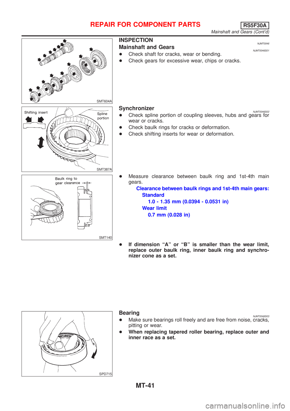
INSPECTIONNJMT0046Mainshaft and GearsNJMT0046S01+Check shaft for cracks, wear or bending.
+Check gears for excessive wear, chips or cracks.
SMT387A
SynchronizerNJMT0046S02+Check spline portion of coupling sleeves, hubs and gears for
wear or cracks.
+Check baulk rings for cracks or deformation.
+Check shifting inserts for wear or deformation.
SMT140
+Measure clearance between baulk ring and 1st-4th main
gears.
Clearance between baulk rings and 1st-4th main gears:
Standard
1.0 - 1.35 mm (0.0394 - 0.0531 in)
Wear limit
0.7 mm (0.028 in)
+If dimension ªAº or ªBº is smaller than the wear limit,
replace outer baulk ring, inner baulk ring and synchro-
nizer cone as a set.
SPD715
BearingNJMT0046S03+Make sure bearings roll freely and are free from noise, cracks,
pitting or wear.
+When replacing tapered roller bearing, replace outer and
inner race as a set.
REPAIR FOR COMPONENT PARTSRS5F30A
Mainshaft and Gears (Cont'd)
MT-41
Page 1092 of 2493
SMT603A
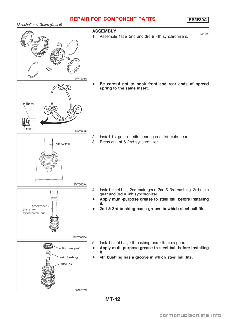
ASSEMBLYNJMT00471. Assemble 1st & 2nd and 3rd & 4th synchronizers.
SMT761B
+Be careful not to hook front and rear ends of spread
spring to the same insert.
SMT605AA
2. Install 1st gear needle bearing and 1st main gear.
3. Press on 1st & 2nd synchronizer.
SMT085CA
4. Install steel ball, 2nd main gear, 2nd & 3rd bushing, 3rd main
gear and 3rd & 4th synchronizer.
+Apply multi-purpose grease to steel ball before installing
it.
+2nd & 3rd bushing has a groove in which steel ball fits.
SMT687C
5. Install steel ball, 4th bushing and 4th main gear.
+Apply multi-purpose grease to steel ball before installing
it.
+4th bushing has a groove in which steel ball fits.
REPAIR FOR COMPONENT PARTSRS5F30A
Mainshaft and Gears (Cont'd)
MT-42
Page 1093 of 2493
SMT606AA
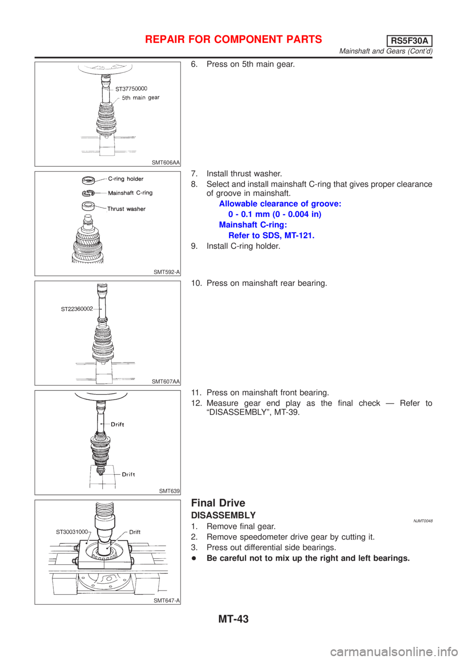
6. Press on 5th main gear.
SMT592-A
7. Install thrust washer.
8. Select and install mainshaft C-ring that gives proper clearance
of groove in mainshaft.
Allowable clearance of groove:
0 - 0.1 mm (0 - 0.004 in)
Mainshaft C-ring:
Refer to SDS, MT-121.
9. Install C-ring holder.
SMT607AA
10. Press on mainshaft rear bearing.
SMT639
11. Press on mainshaft front bearing.
12. Measure gear end play as the final check Ð Refer to
ªDISASSEMBLYº, MT-39.
SMT647-A
Final Drive
DISASSEMBLYNJMT00481. Remove final gear.
2. Remove speedometer drive gear by cutting it.
3. Press out differential side bearings.
+Be careful not to mix up the right and left bearings.
REPAIR FOR COMPONENT PARTSRS5F30A
Mainshaft and Gears (Cont'd)
MT-43
Page 1094 of 2493
SMT147AA
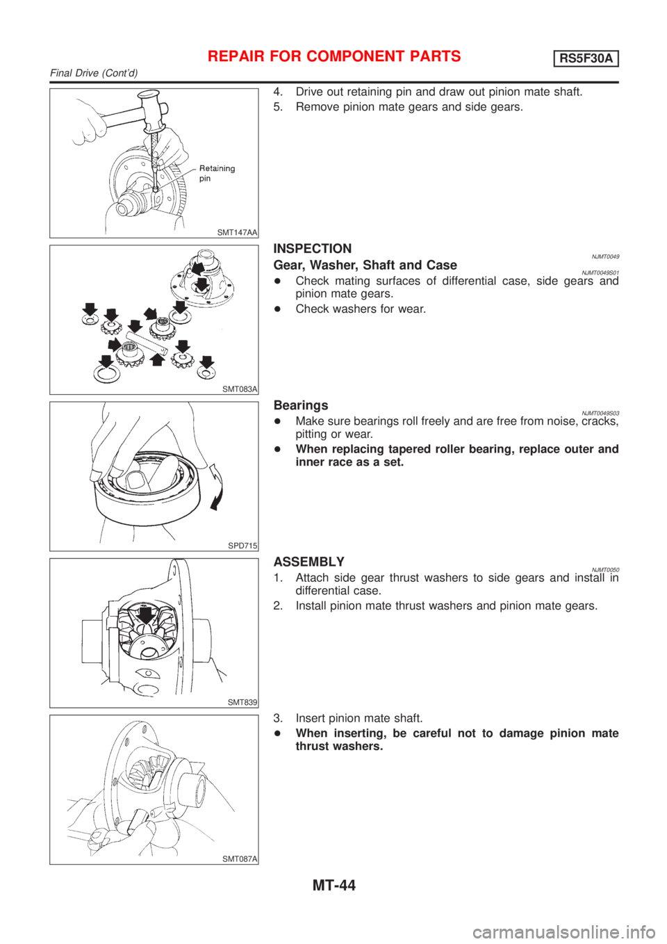
4. Drive out retaining pin and draw out pinion mate shaft.
5. Remove pinion mate gears and side gears.
SMT083A
INSPECTIONNJMT0049Gear, Washer, Shaft and CaseNJMT0049S01+Check mating surfaces of differential case, side gears and
pinion mate gears.
+Check washers for wear.
SPD715
BearingsNJMT0049S03+Make sure bearings roll freely and are free from noise, cracks,
pitting or wear.
+When replacing tapered roller bearing, replace outer and
inner race as a set.
SMT839
ASSEMBLYNJMT00501. Attach side gear thrust washers to side gears and install in
differential case.
2. Install pinion mate thrust washers and pinion mate gears.
SMT087A
3. Insert pinion mate shaft.
+When inserting, be careful not to damage pinion mate
thrust washers.
REPAIR FOR COMPONENT PARTSRS5F30A
Final Drive (Cont'd)
MT-44
Page 1095 of 2493
SMT610AB
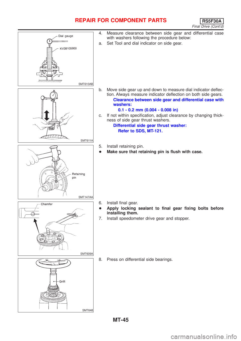
4. Measure clearance between side gear and differential case
with washers following the procedure below:
a. Set Tool and dial indicator on side gear.
SMT611A
b. Move side gear up and down to measure dial indicator deflec-
tion. Always measure indicator deflection on both side gears.
Clearance between side gear and differential case with
washers:
0.1 - 0.2 mm (0.004 - 0.008 in)
c. If not within specification, adjust clearance by changing thick-
ness of side gear thrust washers.
Differential side gear thrust washer:
Refer to SDS, MT-121.
SMT147AA
5. Install retaining pin.
+Make sure that retaining pin is flush with case.
SMT609A
6. Install final gear.
+Apply locking sealant to final gear fixing bolts before
installing them.
7. Install speedometer drive gear and stopper.
SMT648
8. Press on differential side bearings.
REPAIR FOR COMPONENT PARTSRS5F30A
Final Drive (Cont'd)
MT-45
Page 1096 of 2493
SMT086C
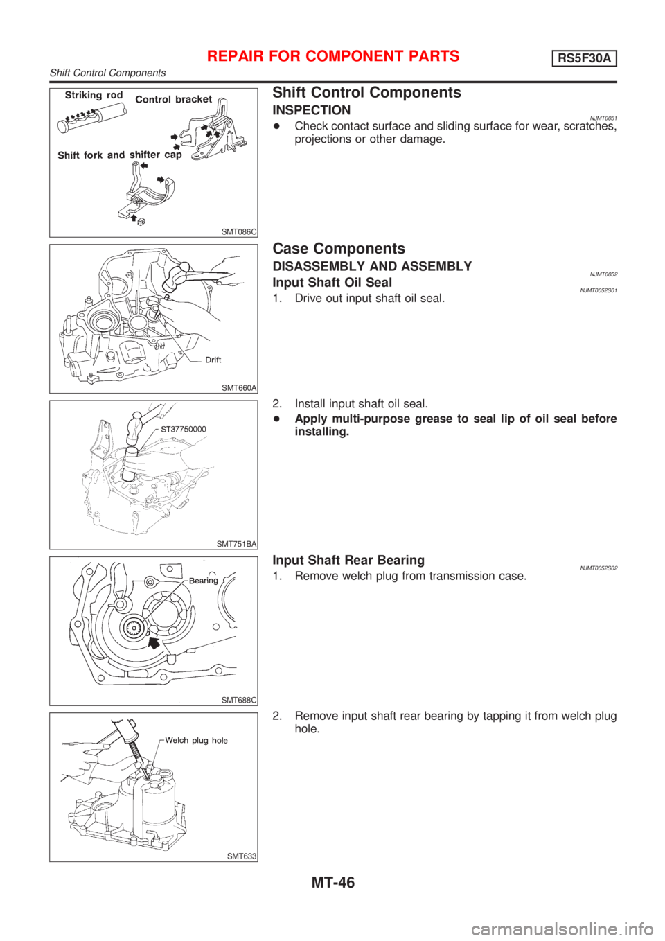
Shift Control Components
INSPECTIONNJMT0051+Check contact surface and sliding surface for wear, scratches,
projections or other damage.
SMT660A
Case Components
DISASSEMBLY AND ASSEMBLYNJMT0052Input Shaft Oil SealNJMT0052S011. Drive out input shaft oil seal.
SMT751BA
2. Install input shaft oil seal.
+Apply multi-purpose grease to seal lip of oil seal before
installing.
SMT688C
Input Shaft Rear BearingNJMT0052S021. Remove welch plug from transmission case.
SMT633
2. Remove input shaft rear bearing by tapping it from welch plug
hole.
REPAIR FOR COMPONENT PARTSRS5F30A
Shift Control Components
MT-46
Page 1097 of 2493
SMT634
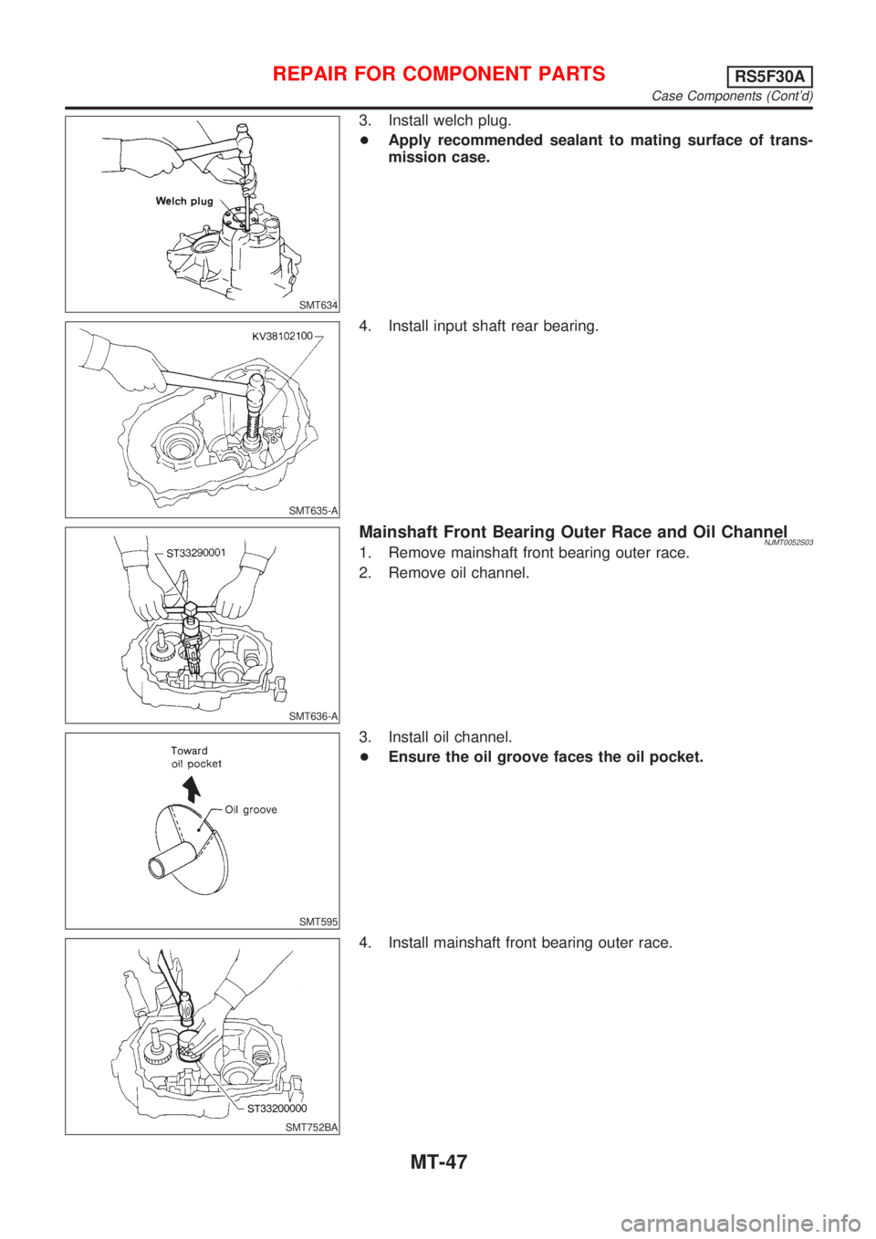
3. Install welch plug.
+Apply recommended sealant to mating surface of trans-
mission case.
SMT635-A
4. Install input shaft rear bearing.
SMT636-A
Mainshaft Front Bearing Outer Race and Oil ChannelNJMT0052S031. Remove mainshaft front bearing outer race.
2. Remove oil channel.
SMT595
3. Install oil channel.
+Ensure the oil groove faces the oil pocket.
SMT752BA
4. Install mainshaft front bearing outer race.
REPAIR FOR COMPONENT PARTSRS5F30A
Case Components (Cont'd)
MT-47
Page 1098 of 2493
Mainshaft Rear Bearing Outer RaceNJMT0052S04+Refer to ªMainshaft Bearing Preloadº, MT-122.
Differential Side Bearing Outer RaceNJMT0052S06+Refer to ªDifferential Side Bearing Preloadº, MT-122.
REPAIR FOR COMPONENT PARTSRS5F30A
Case Components (Cont'd)
MT-48
Page 1099 of 2493
NJMT0091
Differential Side Bearing PreloadNJMT0091S01If any of the following parts are replaced, adjust differential side
bearing preload.
+Differential case
+Differential side bearing
+Clutch housing
+Transmission case
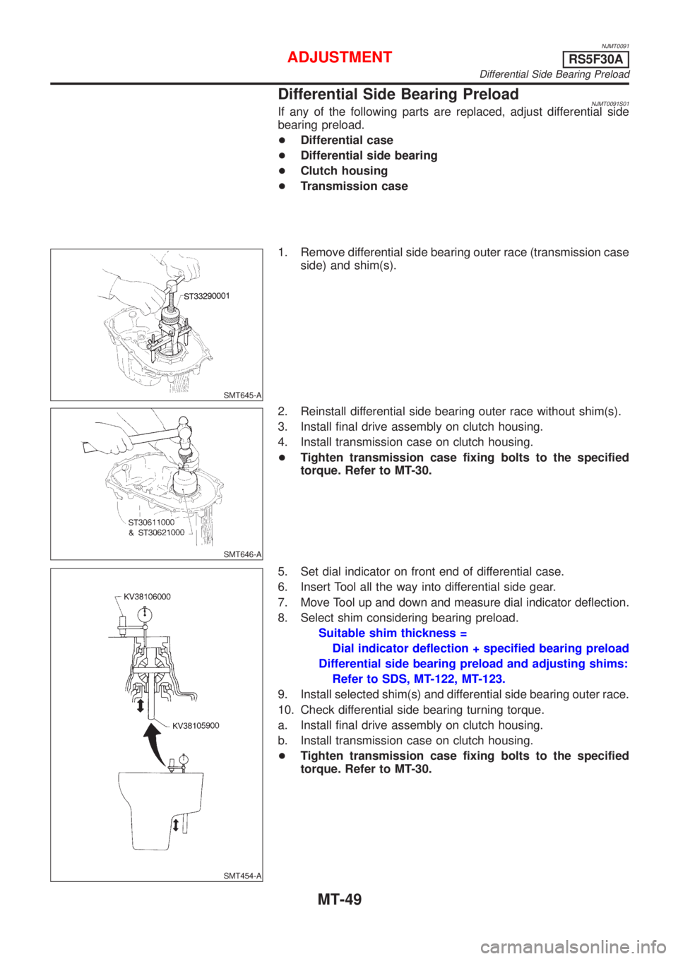
SMT645-A
1. Remove differential side bearing outer race (transmission case
side) and shim(s).
SMT646-A
2. Reinstall differential side bearing outer race without shim(s).
3. Install final drive assembly on clutch housing.
4. Install transmission case on clutch housing.
+Tighten transmission case fixing bolts to the specified
torque. Refer to MT-30.
SMT454-A
5. Set dial indicator on front end of differential case.
6. Insert Tool all the way into differential side gear.
7. Move Tool up and down and measure dial indicator deflection.
8. Select shim considering bearing preload.
Suitable shim thickness =
Dial indicator deflection + specified bearing preload
Differential side bearing preload and adjusting shims:
Refer to SDS, MT-122, MT-123.
9. Install selected shim(s) and differential side bearing outer race.
10. Check differential side bearing turning torque.
a. Install final drive assembly on clutch housing.
b. Install transmission case on clutch housing.
+Tighten transmission case fixing bolts to the specified
torque. Refer to MT-30.
ADJUSTMENTRS5F30A
Differential Side Bearing Preload
MT-49
Page 1100 of 2493
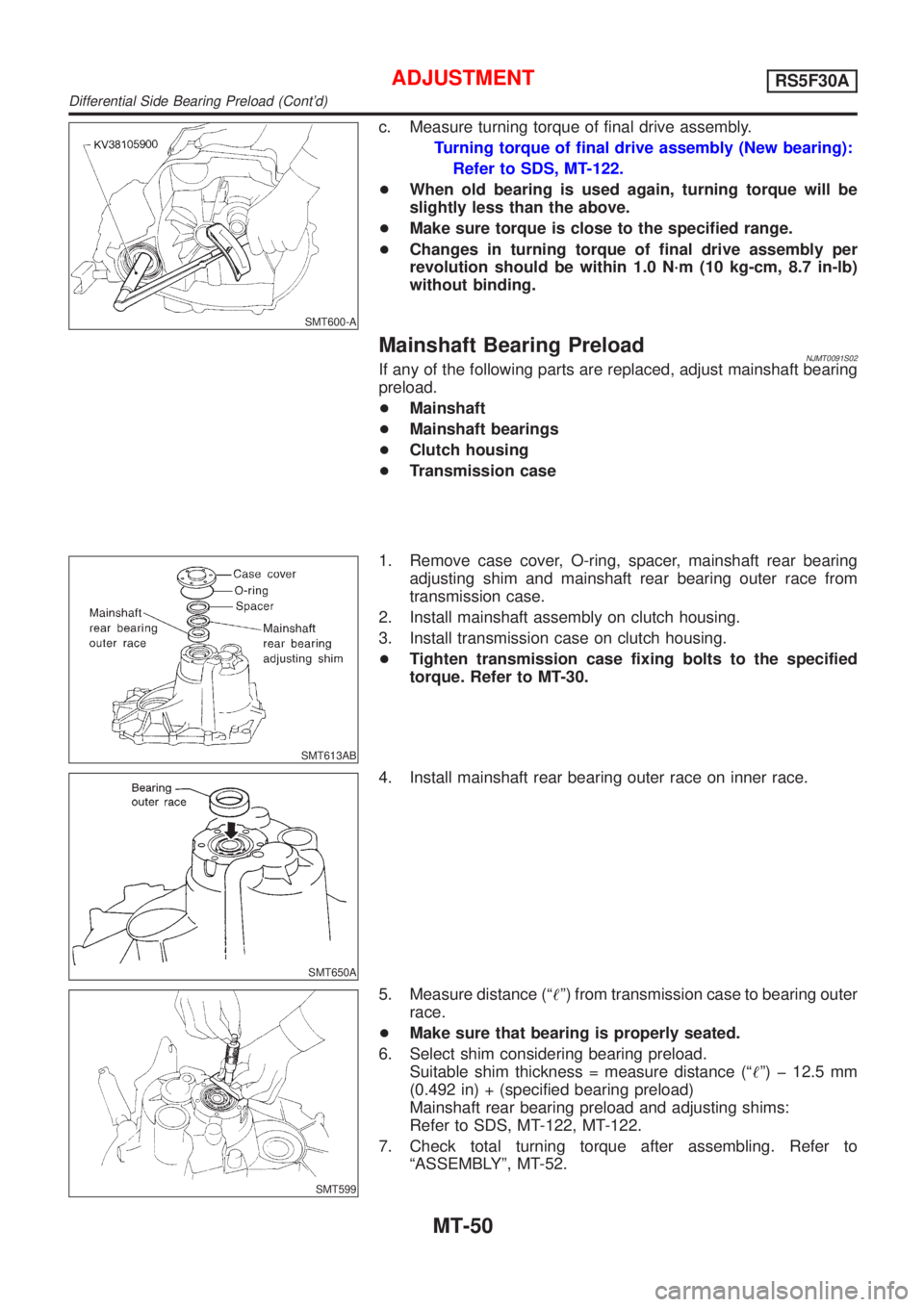
SMT600-A
c. Measure turning torque of final drive assembly.
Turning torque of final drive assembly (New bearing):
Refer to SDS, MT-122.
+When old bearing is used again, turning torque will be
slightly less than the above.
+Make sure torque is close to the specified range.
+Changes in turning torque of final drive assembly per
revolution should be within 1.0 N´m (10 kg-cm, 8.7 in-lb)
without binding.
Mainshaft Bearing PreloadNJMT0091S02If any of the following parts are replaced, adjust mainshaft bearing
preload.
+Mainshaft
+Mainshaft bearings
+Clutch housing
+Transmission case
SMT613AB
1. Remove case cover, O-ring, spacer, mainshaft rear bearing
adjusting shim and mainshaft rear bearing outer race from
transmission case.
2. Install mainshaft assembly on clutch housing.
3. Install transmission case on clutch housing.
+Tighten transmission case fixing bolts to the specified
torque. Refer to MT-30.
SMT650A
4. Install mainshaft rear bearing outer race on inner race.
SMT599
5. Measure distance (ª!º) from transmission case to bearing outer
race.
+Make sure that bearing is properly seated.
6. Select shim considering bearing preload.
Suitable shim thickness = measure distance (ª!º) þ 12.5 mm
(0.492 in) + (specified bearing preload)
Mainshaft rear bearing preload and adjusting shims:
Refer to SDS, MT-122, MT-122.
7. Check total turning torque after assembling. Refer to
ªASSEMBLYº, MT-52.
ADJUSTMENTRS5F30A
Differential Side Bearing Preload (Cont'd)
MT-50