EL page 71 NISSAN ALMERA N16 2001 Electronic Repair Manual
[x] Cancel search | Manufacturer: NISSAN, Model Year: 2001, Model line: ALMERA N16, Model: NISSAN ALMERA N16 2001Pages: 2493, PDF Size: 66.97 MB
Page 2405 of 2493

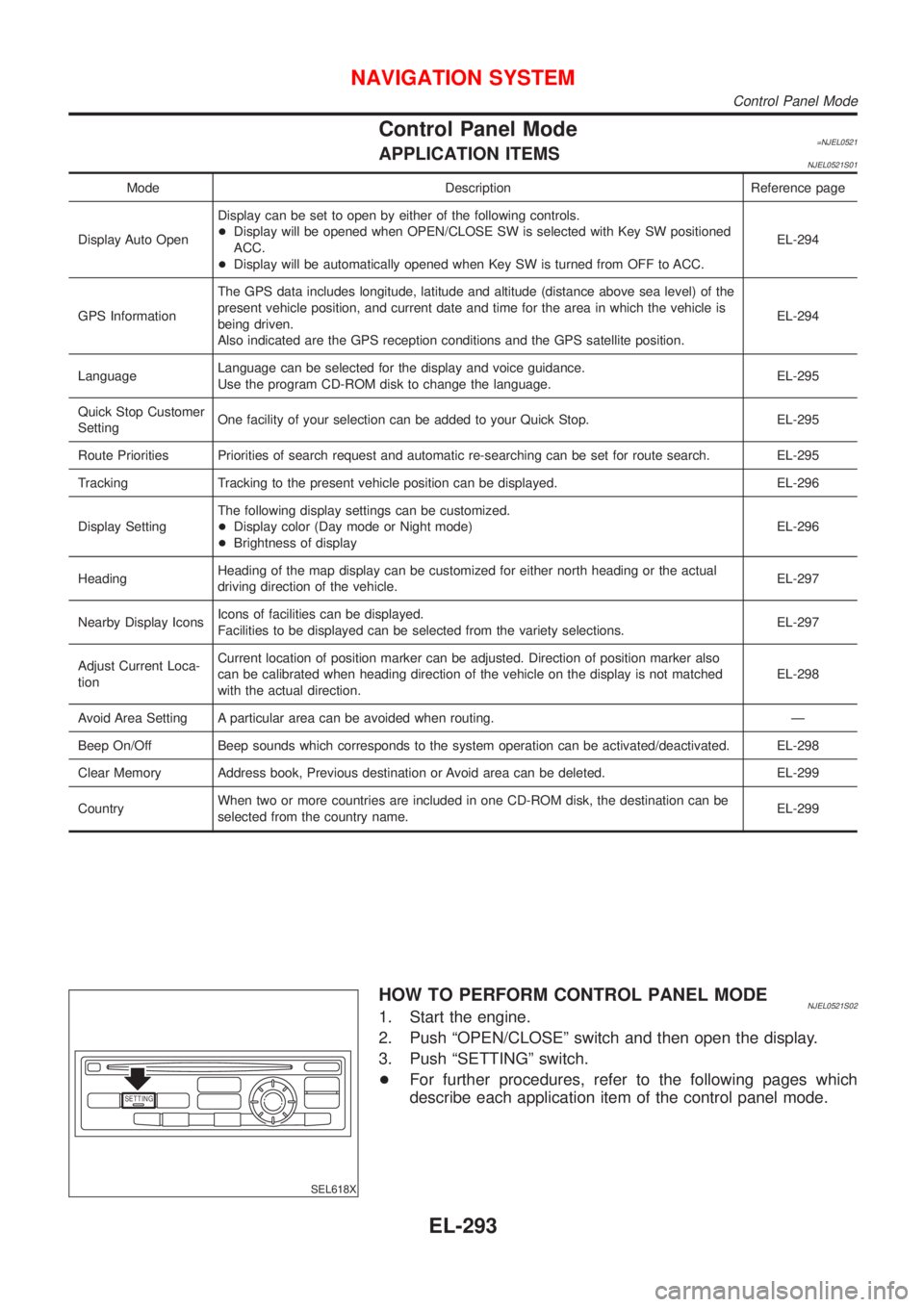
Control Panel Mode=NJEL0521APPLICATION ITEMSNJEL0521S01
Mode Description Reference page
Display Auto OpenDisplay can be set to open by either of the following controls.
+Display will be opened when OPEN/CLOSE SW is selected with Key SW positioned
ACC.
+Display will be automatically opened when Key SW is turned from OFF to ACC.EL-294
GPS InformationThe GPS data includes longitude, latitude and altitude (distance above sea level) of the
present vehicle position, and current date and time for the area in which the vehicle is
being driven.
Also indicated are the GPS reception conditions and the GPS satellite position.EL-294
LanguageLanguage can be selected for the display and voice guidance.
Use the program CD-ROM disk to change the language.EL-295
Quick Stop Customer
SettingOne facility of your selection can be added to your Quick Stop. EL-295
Route Priorities Priorities of search request and automatic re-searching can be set for route search. EL-295
Tracking Tracking to the present vehicle position can be displayed. EL-296
Display SettingThe following display settings can be customized.
+Display color (Day mode or Night mode)
+Brightness of displayEL-296
HeadingHeading of the map display can be customized for either north heading or the actual
driving direction of the vehicle.EL-297
Nearby Display IconsIcons of facilities can be displayed.
Facilities to be displayed can be selected from the variety selections.EL-297
Adjust Current Loca-
tionCurrent location of position marker can be adjusted. Direction of position marker also
can be calibrated when heading direction of the vehicle on the display is not matched
with the actual direction.EL-298
Avoid Area Setting A particular area can be avoided when routing. Ð
Beep On/Off Beep sounds which corresponds to the system operation can be activated/deactivated. EL-298
Clear Memory Address book, Previous destination or Avoid area can be deleted. EL-299
CountryWhen two or more countries are included in one CD-ROM disk, the destination can be
selected from the country name.EL-299
SETTING
SEL618X
HOW TO PERFORM CONTROL PANEL MODENJEL0521S021. Start the engine.
2. Push ªOPEN/CLOSEº switch and then open the display.
3. Push ªSETTINGº switch.
+For further procedures, refer to the following pages which
describe each application item of the control panel mode.
NAVIGATION SYSTEM
Control Panel Mode
EL-293
Page 2415 of 2493

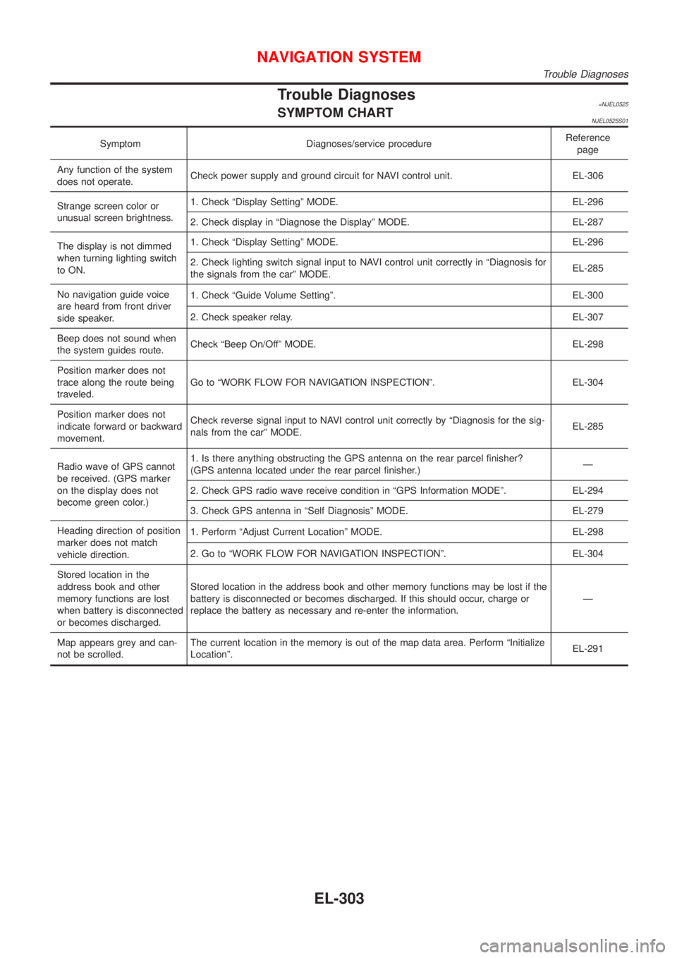
Trouble Diagnoses=NJEL0525SYMPTOM CHARTNJEL0525S01
Symptom Diagnoses/service procedureReference
page
Any function of the system
does not operate.Check power supply and ground circuit for NAVI control unit. EL-306
Strange screen color or
unusual screen brightness.1. Check ªDisplay Settingº MODE. EL-296
2. Check display in ªDiagnose the Displayº MODE. EL-287
The display is not dimmed
when turning lighting switch
to ON.1. Check ªDisplay Settingº MODE. EL-296
2. Check lighting switch signal input to NAVI control unit correctly in ªDiagnosis for
the signals from the carº MODE.EL-285
No navigation guide voice
are heard from front driver
side speaker.1. Check ªGuide Volume Settingº. EL-300
2. Check speaker relay. EL-307
Beep does not sound when
the system guides route.Check ªBeep On/Offº MODE. EL-298
Position marker does not
trace along the route being
traveled.Go to ªWORK FLOW FOR NAVIGATION INSPECTIONº. EL-304
Position marker does not
indicate forward or backward
movement.Check reverse signal input to NAVI control unit correctly by ªDiagnosis for the sig-
nals from the carº MODE.EL-285
Radio wave of GPS cannot
be received. (GPS marker
on the display does not
become green color.)1. Is there anything obstructing the GPS antenna on the rear parcel finisher?
(GPS antenna located under the rear parcel finisher.)Ð
2. Check GPS radio wave receive condition in ªGPS Information MODEº. EL-294
3. Check GPS antenna in ªSelf Diagnosisº MODE. EL-279
Heading direction of position
marker does not match
vehicle direction.1. Perform ªAdjust Current Locationº MODE. EL-298
2. Go to ªWORK FLOW FOR NAVIGATION INSPECTIONº. EL-304
Stored location in the
address book and other
memory functions are lost
when battery is disconnected
or becomes discharged.Stored location in the address book and other memory functions may be lost if the
battery is disconnected or becomes discharged. If this should occur, charge or
replace the battery as necessary and re-enter the information.Ð
Map appears grey and can-
not be scrolled.The current location in the memory is out of the map data area. Perform ªInitialize
Locationº.EL-291
NAVIGATION SYSTEM
Trouble Diagnoses
EL-303
Page 2423 of 2493

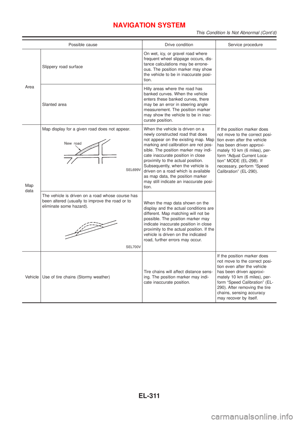
Possible cause Drive condition Service procedure
AreaSlippery road surfaceOn wet, icy, or gravel road where
frequent wheel slippage occurs, dis-
tance calculations may be errone-
ous. The position marker may show
the vehicle to be in inaccurate posi-
tion.
If the position marker does
not move to the correct posi-
tion even after the vehicle
has been driven approxi-
mately 10 km (6 miles), per-
form ªAdjust Current Loca-
tionº MODE (EL-298). If
necessary, perform ªSpeed
Calibrationº (EL-290). Slanted areaHilly areas where the road has
banked curves. When the vehicle
enters these banked curves, there
may be an error in steering angle
measurement. The position marker
may show the vehicle to be in inac-
curate position.
Map
dataMap display for a given road does not appear.
SEL699V
When the vehicle is driven on a
newly constructed road that does
not appear on the existing map. Map
marking and calibration are not pos-
sible. The position marker may indi-
cate inaccurate position in close
proximity to the actual position.
Subsequently, when the vehicle is
driven on a road which is available
as map data, the position marker
may still indicate an inaccurate posi-
tion.
The vehicle is driven on a road whose course has
been altered (usually to improve the road or to
eliminate some hazard).
SEL700V
When the map data shown on the
display and the actual conditions are
different. Map matching will not be
possible. The position marker may
indicate inaccurate position in close
proximity to the actual position. If the
vehicle is driven on the indicated
road, further errors may occur.
Vehicle Use of tire chains (Stormy weather)Tire chains will affect distance sens-
ing. The position marker may indi-
cate inaccurate position.If the position marker does
not move to the correct posi-
tion even after the vehicle
has been driven approxi-
mately 10 km (6 miles), per-
form ªSpeed Calibrationº (EL-
290). After removing the tire
chains, sensing accuracy
may recover by itself.
NAVIGATION SYSTEM
This Condition Is Not Abnormal (Cont'd)
EL-311
Page 2479 of 2493

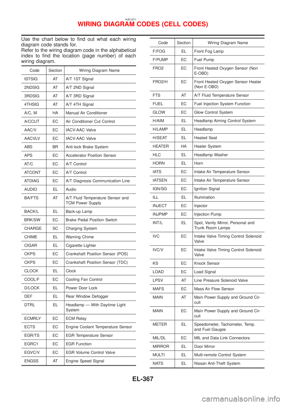
NJEL0311
Use the chart below to find out what each wiring
diagram code stands for.
Refer to the wiring diagram code in the alphabetical
index to find the location (page number) of each
wiring diagram.
Code Section Wiring Diagram Name
ISTSIG AT A/T 1ST Signal
2NDSIG AT A/T 2ND Signal
3RDSIG AT A/T 3RD Signal
4THSIG AT A/T 4TH Signal
A/C, M HA Manual Air Conditioner
A/CCUT EC Air Conditioner Cut Control
AAC/V EC IACV-AAC Valve
AACVLV EC IACV-AAC Valve
ABS BR Anti-lock Brake System
APS EC Accelerator Position Sensor
AT/C EC A/T Control
ATCONT EC A/T Control
ATDIAG EC A/T Diagnosis Communication Line
AUDIO EL Audio
BA/FTS AT A/T Fluid Temperature Sensor and
TCM Power Supply
BACK/L EL Back-up Lamp
BRK/SW EC Brake Pedal Position Switch
CHARGE SC Charging System
CHIME EL Warning Chime
CIGAR EL Cigarette Lighter
CKPS EC Crankshaft Position Sensor (POS)
CKPS EC Crankshaft Position Sensor (TDC)
CLOCK EL Clock
COOL/F EC Cooling Fan Control
D/LOCK EL Power Door Lock
DEF EL Rear Window Defogger
DTRL EL Headlamp Ð With Daytime Light
System
ECMRLY EC ECM Relay
ECTS EC Engine Coolant Temperature Sensor
EGR/TS EC EGR Temperature Sensor
EGRC1 EC EGR Function
EGVC/V EC EGR Volume Control Valve
ENGSS AT Engine Speed Signal
Code Section Wiring Diagram Name
F/FOG EL Front Fog Lamp
F/PUMP EC Fuel Pump
FRO2 EC Front Heated Oxygen Sensor (Non
E-OBD)
FRO2/H EC Front Heated Oxygen Sensor Heater
(Non E-OBD)
FTS AT A/T Fluid Temperature Sensor
FUEL EC Fuel Injection System Function
GLOW EC Glow Control System
H/AIM EL Headlamp Aiming Control System
H/LAMP EL Headlamp
H/SEAT EL Heated Seat
HEATER HA Heater System
HLC EL Headlamp Washer
HORN EL Horn
IATS EC Intake Air Temperature Sensor
IATSEN EC Intake Air Temperature Sensor
IGN/SG EC Ignition Signal
ILL EL Illumination
INJECT EC Injector
INJPMP EC Injection Pump
INT/L EL Spot, Vanity Mirror, Personal and
Trunk Room Lamps
IVC EC Intake Valve Timing Control Solenoid
Valve
IVC/V EC Intake Valve Timing Control Solenoid
Valve
KS EC Knock Sensor
LOAD EC Load Signal
LPSV AT Line Pressure Solenoid Valve
MAFS EC Mass Air Flow Sensor
MAIN AT Main Power Supply and Ground Cir-
cuit
MAIN EC Main Power Supply and Ground Cir-
cuit
METER EL Speedometer, Tachometer, Temp.
and Fuel Gauges
MIL/DL EC MIL and Data Link Connectors
MIRROR EL Door Mirror
MULTI EL Multi-remote Control System
NATS EL Nissan Anti-Theft System
WIRING DIAGRAM CODES (CELL CODES)
EL-367
Page 2489 of 2493

PLEASE HELP US TO IMPROVE THIS
SERVICE MANUAL ON CD!
Your comments are important to NISSAN and will help us to improve our
Service Manuals on CD. Use this form to report any issues or comments you
may have regarding this Service Manual publication.
Please print this form and type or print your comments below. Mail or fax to:
NISSANEUROP EN.V.
S320 Service Engineering
2, Avenue de Denis Papin
ZIPEC - F92350 Le Plessis Robinson
France
Fax :+ 33 (0) 1 41 07 16 81
SERVICE MANUAL: Model:Language:
Publication Number:
Please describe any issues or problems in detail:
Page number(s):
Note: Please include acopy ofeach page, marked withyour comments.
Is the organization of the manual clear and easy to follow? (circle your answer) YES NO
Please comment:
What information should be included in NISSAN Service Manuals to better support you in
servicing or repairing customer vehicles?
Date :
Your Name :Position :
Dealer :Dealer No. :
Address :
City :Country :
Telephone :
Fax :
E-mail :