NISSAN ALMERA N16 2001 Electronic Repair Manual
Manufacturer: NISSAN, Model Year: 2001, Model line: ALMERA N16, Model: NISSAN ALMERA N16 2001Pages: 2493, PDF Size: 66.97 MB
Page 1221 of 2493
SAT015J
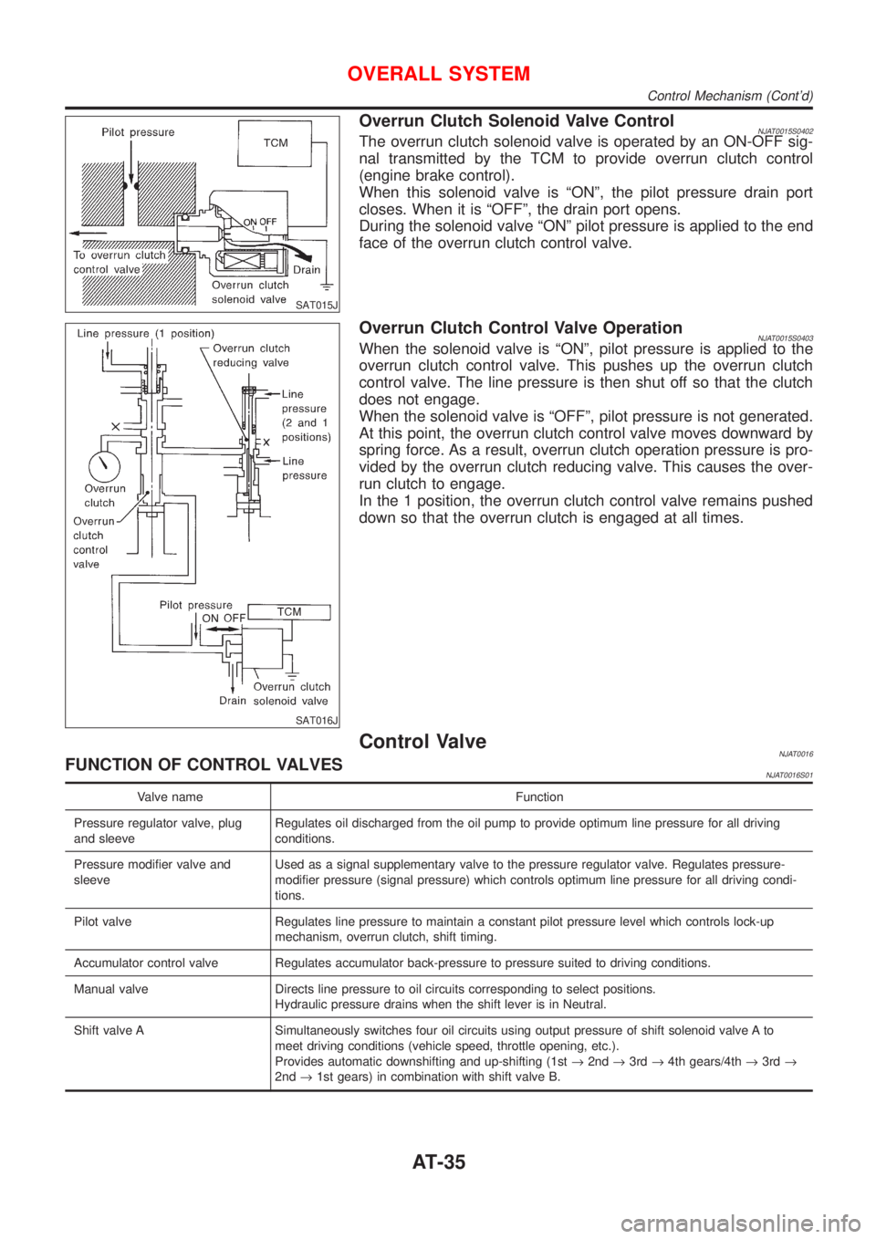
Overrun Clutch Solenoid Valve ControlNJAT0015S0402The overrun clutch solenoid valve is operated by an ON-OFF sig-
nal transmitted by the TCM to provide overrun clutch control
(engine brake control).
When this solenoid valve is ªONº, the pilot pressure drain port
closes. When it is ªOFFº, the drain port opens.
During the solenoid valve ªONº pilot pressure is applied to the end
face of the overrun clutch control valve.
SAT016J
Overrun Clutch Control Valve OperationNJAT0015S0403When the solenoid valve is ªONº, pilot pressure is applied to the
overrun clutch control valve. This pushes up the overrun clutch
control valve. The line pressure is then shut off so that the clutch
does not engage.
When the solenoid valve is ªOFFº, pilot pressure is not generated.
At this point, the overrun clutch control valve moves downward by
spring force. As a result, overrun clutch operation pressure is pro-
vided by the overrun clutch reducing valve. This causes the over-
run clutch to engage.
In the 1 position, the overrun clutch control valve remains pushed
down so that the overrun clutch is engaged at all times.
Control ValveNJAT0016FUNCTION OF CONTROL VALVESNJAT0016S01
Valve name Function
Pressure regulator valve, plug
and sleeveRegulates oil discharged from the oil pump to provide optimum line pressure for all driving
conditions.
Pressure modifier valve and
sleeveUsed as a signal supplementary valve to the pressure regulator valve. Regulates pressure-
modifier pressure (signal pressure) which controls optimum line pressure for all driving condi-
tions.
Pilot valve Regulates line pressure to maintain a constant pilot pressure level which controls lock-up
mechanism, overrun clutch, shift timing.
Accumulator control valve Regulates accumulator back-pressure to pressure suited to driving conditions.
Manual valve Directs line pressure to oil circuits corresponding to select positions.
Hydraulic pressure drains when the shift lever is in Neutral.
Shift valve A Simultaneously switches four oil circuits using output pressure of shift solenoid valve A to
meet driving conditions (vehicle speed, throttle opening, etc.).
Provides automatic downshifting and up-shifting (1st®2nd®3rd®4th gears/4th®3rd®
2nd®1st gears) in combination with shift valve B.
OVERALL SYSTEM
Control Mechanism (Cont'd)
AT-35
Page 1222 of 2493
Valve name Function
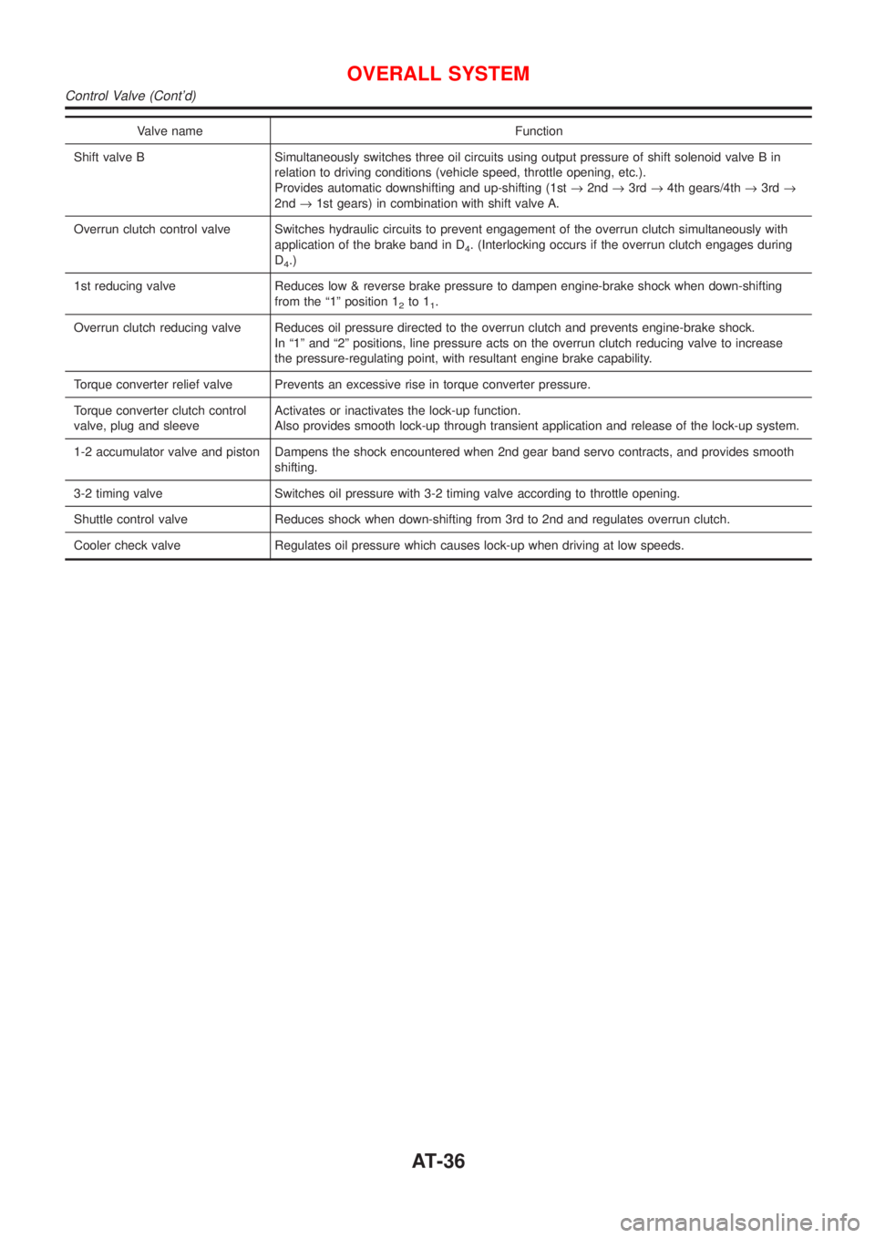
Shift valve B Simultaneously switches three oil circuits using output pressure of shift solenoid valve B in
relation to driving conditions (vehicle speed, throttle opening, etc.).
Provides automatic downshifting and up-shifting (1st®2nd®3rd®4th gears/4th®3rd®
2nd®1st gears) in combination with shift valve A.
Overrun clutch control valve Switches hydraulic circuits to prevent engagement of the overrun clutch simultaneously with
application of the brake band in D
4. (Interlocking occurs if the overrun clutch engages during
D
4.)
1st reducing valve Reduces low & reverse brake pressure to dampen engine-brake shock when down-shifting
from the ª1º position 1
2to 11.
Overrun clutch reducing valve Reduces oil pressure directed to the overrun clutch and prevents engine-brake shock.
In ª1º and ª2º positions, line pressure acts on the overrun clutch reducing valve to increase
the pressure-regulating point, with resultant engine brake capability.
Torque converter relief valve Prevents an excessive rise in torque converter pressure.
Torque converter clutch control
valve, plug and sleeveActivates or inactivates the lock-up function.
Also provides smooth lock-up through transient application and release of the lock-up system.
1-2 accumulator valve and piston Dampens the shock encountered when 2nd gear band servo contracts, and provides smooth
shifting.
3-2 timing valve Switches oil pressure with 3-2 timing valve according to throttle opening.
Shuttle control valve Reduces shock when down-shifting from 3rd to 2nd and regulates overrun clutch.
Cooler check valve Regulates oil pressure which causes lock-up when driving at low speeds.
OVERALL SYSTEM
Control Valve (Cont'd)
AT-36
Page 1223 of 2493
CONSULT-IINJAT0022After performing ªSELF-DIAGNOSTIC PROCEDURE (WITH CON-
SULT-II)º (AT-37), place check marks for results on the ªDIAGNOS-
TIC WORKSHEETº, AT-69. Reference pages are provided follow-
ing the items.
NOTICE:
1) The CONSULT-II electrically displays shift timing and lock-up
timing (that is, operation timing of each solenoid).
Check for time difference between actual shift timing and the
CONSULT-II display. If the difference is noticeable, mechani-
cal parts (except solenoids, sensors, etc.) may be malfunction-
ing. Check mechanical parts using applicable diagnostic pro-
cedures.
2) Shift schedule (which implies gear position) displayed on
CONSULT-II and that indicated in Service Manual may differ
slightly. This occurs because of the following reasons:
+Actual shift schedule has more or less tolerance or allowance,
+Shift schedule indicated in Service Manual refers to the point
where shifts start, and
+Gear position displayed on CONSULT-II indicates the point
where shifts are completed.
3) Shift solenoid valve ªAº or ªBº is displayed on CONSULT-II at
the start of shifting. Gear position is displayed upon completion
of shifting (which is computed by TCM).
4) Additional CONSULT-II information can be found in the Opera-
tion Manual supplied with the CONSULT-II unit.
SAT580J
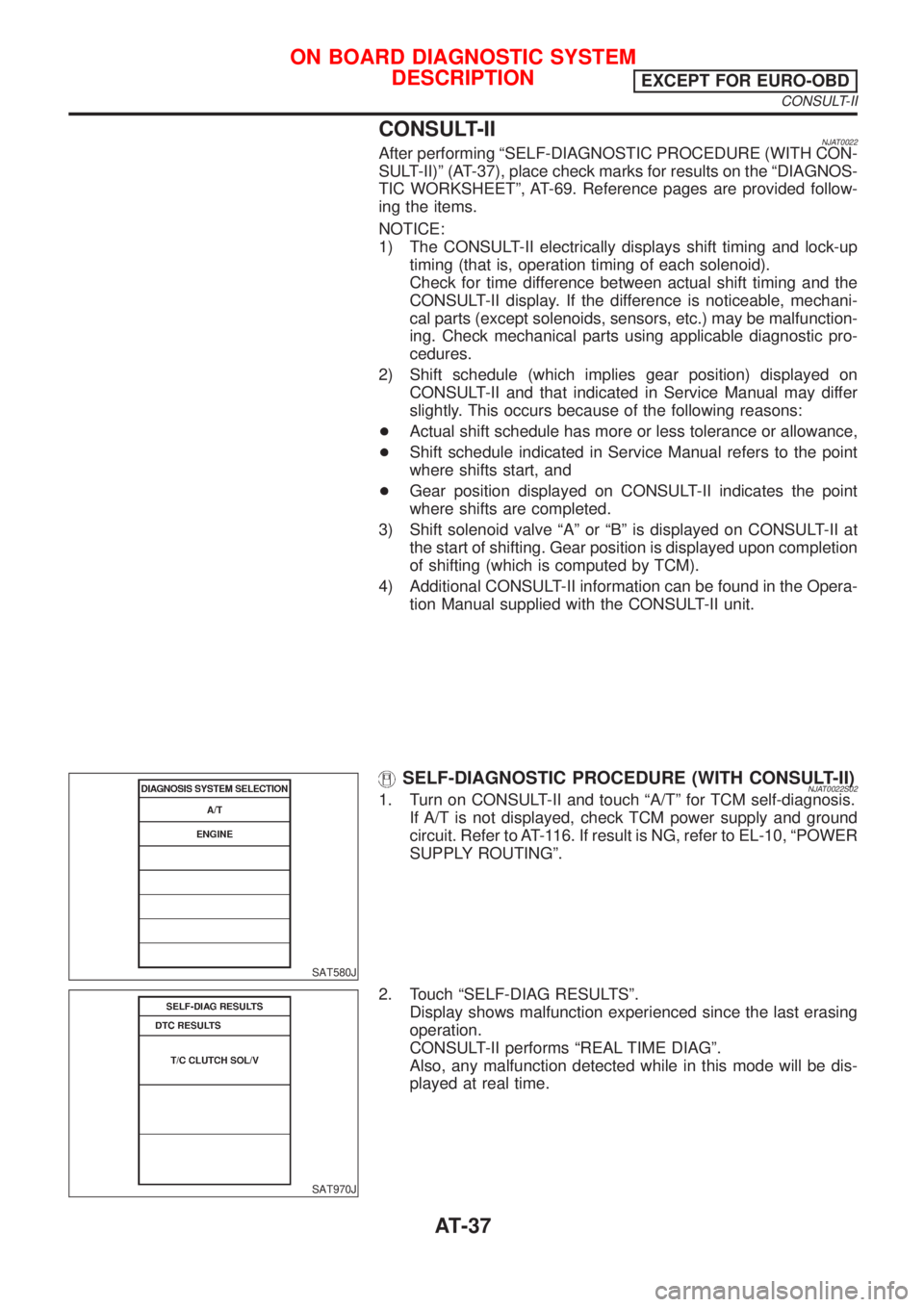
SELF-DIAGNOSTIC PROCEDURE (WITH CONSULT-II)NJAT0022S021. Turn on CONSULT-II and touch ªA/Tº for TCM self-diagnosis.
If A/T is not displayed, check TCM power supply and ground
circuit. Refer to AT-116. If result is NG, refer to EL-10, ªPOWER
SUPPLY ROUTINGº.
SAT970J
2. Touch ªSELF-DIAG RESULTSº.
Display shows malfunction experienced since the last erasing
operation.
CONSULT-II performs ªREAL TIME DIAGº.
Also, any malfunction detected while in this mode will be dis-
played at real time.
ON BOARD DIAGNOSTIC SYSTEM
DESCRIPTION
EXCEPT FOR EURO-OBD
CONSULT-II
AT-37
Page 1224 of 2493
SELF-DIAGNOSTIC RESULT TEST MODENJAT0022S03
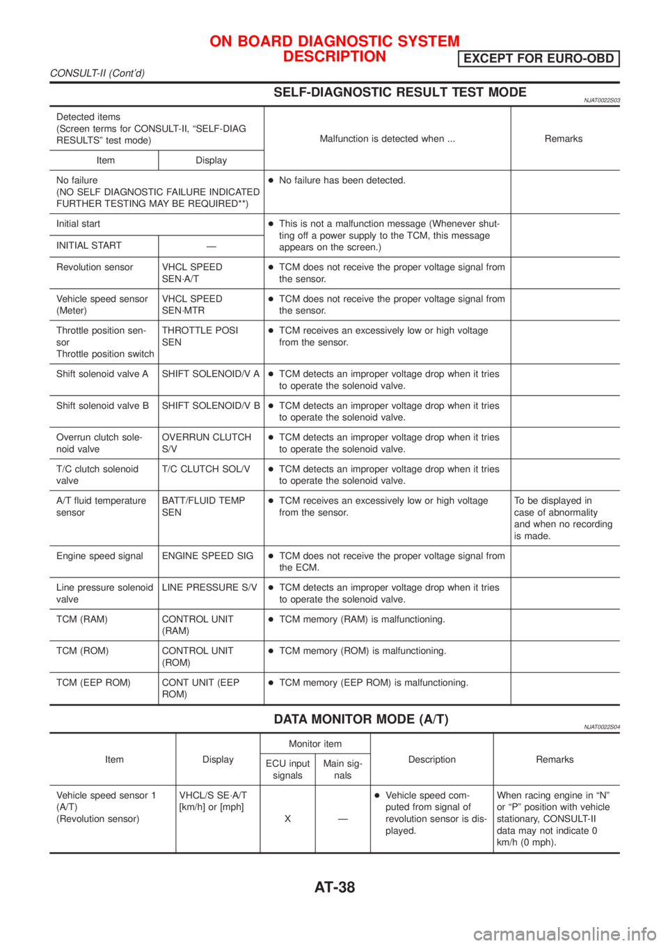
Detected items
(Screen terms for CONSULT-II, ªSELF-DIAG
RESULTSº test mode)Malfunction is detected when ... Remarks
Item Display
No failure
(NO SELF DIAGNOSTIC FAILURE INDICATED
FURTHER TESTING MAY BE REQUIRED**)+No failure has been detected.
Initial start+This is not a malfunction message (Whenever shut-
ting off a power supply to the TCM, this message
appears on the screen.) INITIAL START
Ð
Revolution sensor VHCL SPEED
SEN´A/T+TCM does not receive the proper voltage signal from
the sensor.
Vehicle speed sensor
(Meter)VHCL SPEED
SEN´MTR+TCM does not receive the proper voltage signal from
the sensor.
Throttle position sen-
sor
Throttle position switchTHROTTLE POSI
SEN+TCM receives an excessively low or high voltage
from the sensor.
Shift solenoid valve A SHIFT SOLENOID/V A+TCM detects an improper voltage drop when it tries
to operate the solenoid valve.
Shift solenoid valve B SHIFT SOLENOID/V B+TCM detects an improper voltage drop when it tries
to operate the solenoid valve.
Overrun clutch sole-
noid valveOVERRUN CLUTCH
S/V+TCM detects an improper voltage drop when it tries
to operate the solenoid valve.
T/C clutch solenoid
valveT/C CLUTCH SOL/V+TCM detects an improper voltage drop when it tries
to operate the solenoid valve.
A/T fluid temperature
sensorBATT/FLUID TEMP
SEN+TCM receives an excessively low or high voltage
from the sensor.To be displayed in
case of abnormality
and when no recording
is made.
Engine speed signal ENGINE SPEED SIG+TCM does not receive the proper voltage signal from
the ECM.
Line pressure solenoid
valveLINE PRESSURE S/V+TCM detects an improper voltage drop when it tries
to operate the solenoid valve.
TCM (RAM) CONTROL UNIT
(RAM)+TCM memory (RAM) is malfunctioning.
TCM (ROM) CONTROL UNIT
(ROM)+TCM memory (ROM) is malfunctioning.
TCM (EEP ROM) CONT UNIT (EEP
ROM)+TCM memory (EEP ROM) is malfunctioning.
DATA MONITOR MODE (A/T)NJAT0022S04
Item DisplayMonitor item
Description Remarks
ECU input
signalsMain sig-
nals
Vehicle speed sensor 1
(A/T)
(Revolution sensor)VHCL/S SE´A/T
[km/h] or [mph]
XÐ+Vehicle speed com-
puted from signal of
revolution sensor is dis-
played.When racing engine in ªNº
or ªPº position with vehicle
stationary, CONSULT-II
data may not indicate 0
km/h (0 mph).
ON BOARD DIAGNOSTIC SYSTEM
DESCRIPTION
EXCEPT FOR EURO-OBD
CONSULT-II (Cont'd)
AT-38
Page 1225 of 2493
![NISSAN ALMERA N16 2001 Electronic Repair Manual Item DisplayMonitor item
Description Remarks
ECU input
signalsMain sig-
nals
Vehicle speed sensor 2
(Meter)VHCL/S SE´MTR
[km/h] or [mph]
XÐ+Vehicle speed com-
puted from signal of
vehicle speed sens NISSAN ALMERA N16 2001 Electronic Repair Manual Item DisplayMonitor item
Description Remarks
ECU input
signalsMain sig-
nals
Vehicle speed sensor 2
(Meter)VHCL/S SE´MTR
[km/h] or [mph]
XÐ+Vehicle speed com-
puted from signal of
vehicle speed sens](/img/5/57351/w960_57351-1224.png)
Item DisplayMonitor item
Description Remarks
ECU input
signalsMain sig-
nals
Vehicle speed sensor 2
(Meter)VHCL/S SE´MTR
[km/h] or [mph]
XÐ+Vehicle speed com-
puted from signal of
vehicle speed sensor is
displayed.Vehicle speed display may
not be accurate under
approx. 10 km/h (6 mph).
It may not indicate 0 km/h
(0 mph) when vehicle is
stationary.
Throttle position sensor THRTL POS SEN
[V] X Ð+Throttle position sensor
signal voltage is dis-
played.
A/T fluid temperature sen-
sorFLUID TEMP SE
[V]
XÐ+A/T fluid temperature
sensor signal voltage is
displayed.
+Signal voltage lowers as
fluid temperature rises.
Battery voltage BATTERY VOLT
[V]XÐ+Source voltage of TCM
is displayed.
Engine speed ENGINE SPEED
[rpm]
XX+Engine speed, com-
puted from engine
speed signal, is dis-
played.Engine speed display may
not be accurate under
approx. 800 rpm. It may
not indicate 0 rpm even
when engine is not run-
ning.
Overdrive control switch OVERDRIVE SW
[ON/OFF]
XÐ+ON/OFF state com-
puted from signal of
overdrive control SW is
displayed.
P/N position switch PN POSI SW
[ON/OFF]
XÐ+ON/OFF state com-
puted from signal of P/N
position SW is dis-
played.
R position switch R POSITION SW
[ON/OFF]
XÐ+ON/OFF state com-
puted from signal of R
position SW is dis-
played.
D position switch D POSITION SW
[ON/OFF]
XÐ+ON/OFF state com-
puted from signal of D
position SW is dis-
played.
2 position switch 2 POSITION SW
[ON/OFF]
XÐ+ON/OFF status, com-
puted from signal of 2
position SW, is dis-
played.
1 position switch 1 POSITION SW
[ON/OFF]
XÐ+ON/OFF status, com-
puted from signal of 1
position SW, is dis-
played.
ASCD cruise signal ASCD-CRUISE
[ON/OFF]
XÐ+Status of ASCD cruise
signal is displayed.
ON ... Cruising state
OFF ... Normal running
state+This is displayed even
when no ASCD is
mounted.
ON BOARD DIAGNOSTIC SYSTEM
DESCRIPTION
EXCEPT FOR EURO-OBD
CONSULT-II (Cont'd)
AT-39
Page 1226 of 2493
![NISSAN ALMERA N16 2001 Electronic Repair Manual Item DisplayMonitor item
Description Remarks
ECU input
signalsMain sig-
nals
ASCD OD cut signal ASCD-OD CUT
[ON/OFF]
XÐ+Status of ASCD OD
release signal is dis-
played.
ON ... OD released
OFF ... OD NISSAN ALMERA N16 2001 Electronic Repair Manual Item DisplayMonitor item
Description Remarks
ECU input
signalsMain sig-
nals
ASCD OD cut signal ASCD-OD CUT
[ON/OFF]
XÐ+Status of ASCD OD
release signal is dis-
played.
ON ... OD released
OFF ... OD](/img/5/57351/w960_57351-1225.png)
Item DisplayMonitor item
Description Remarks
ECU input
signalsMain sig-
nals
ASCD OD cut signal ASCD-OD CUT
[ON/OFF]
XÐ+Status of ASCD OD
release signal is dis-
played.
ON ... OD released
OFF ... OD not released+This is displayed even
when no ASCD is
mounted.
Kickdown switch KICKDOWN SW
[ON/OFF]
XÐ+ON/OFF status, com-
puted from signal of
kickdown SW, is dis-
played.+This is displayed even
when no kickdown
switch is equipped.
Closed throttle position
switchCLOSED
THL/SW
[ON/OFF]XÐ+ON/OFF status, com-
puted from signal of
closed throttle position
SW, is displayed.
Wide open throttle position
switchW/O THRL/P-SW
[ON/OFF]
XÐ+ON/OFF status, com-
puted from signal of
wide open throttle posi-
tion SW, is displayed.
Gear position GEAR
ÐX+Gear position data used
for computation by
TCM, is displayed.
Selector lever position SLCT LVR POSI
ÐX+Selector lever position
data, used for computa-
tion by TCM, is dis-
played.+A specific value used
for control is displayed if
fail-safe is activated due
to error.
Vehicle speed VEHICLE SPEED
[km/h] or [mph] Ð X+Vehicle speed data,
used for computation by
TCM, is displayed.
Stop lamp switch BRAKE SW
[ON/OFF]
XÐ+ON/OFF status are dis-
played.
ON: Brake pedal is
depressed.
OFF: Brake pedal is
released.
Throttle position THROTTLE POSI
[/8]
ÐX+Throttle position data,
used for computation by
TCM, is displayed.+A specific value used
for control is displayed if
fail-safe is activated due
to error.
Line pressure duty LINE PRES DTY
[%]
ÐX+Control value of line
pressure solenoid valve,
computed by TCM from
each input signal, is dis-
played.
Torque converter clutch
solenoid valve dutyTCC S/V DUTY
[%]
ÐX+Control value of torque
converter clutch sole-
noid valve, computed by
TCM from each input
signal, is displayed.
ON BOARD DIAGNOSTIC SYSTEM
DESCRIPTION
EXCEPT FOR EURO-OBD
CONSULT-II (Cont'd)
AT-40
Page 1227 of 2493
![NISSAN ALMERA N16 2001 Electronic Repair Manual Item DisplayMonitor item
Description Remarks
ECU input
signalsMain sig-
nals
Shift solenoid valve A SHIFT S/V A
[ON/OFF]
ÐX+Control value of shift
solenoid valve A, com-
puted by TCM from
each input NISSAN ALMERA N16 2001 Electronic Repair Manual Item DisplayMonitor item
Description Remarks
ECU input
signalsMain sig-
nals
Shift solenoid valve A SHIFT S/V A
[ON/OFF]
ÐX+Control value of shift
solenoid valve A, com-
puted by TCM from
each input](/img/5/57351/w960_57351-1226.png)
Item DisplayMonitor item
Description Remarks
ECU input
signalsMain sig-
nals
Shift solenoid valve A SHIFT S/V A
[ON/OFF]
ÐX+Control value of shift
solenoid valve A, com-
puted by TCM from
each input signal, is dis-
played.Control value of solenoid
is displayed even if sole-
noid circuit is discon-
nected.
The ªOFFº signal is dis-
played if solenoid circuit is
shorted. Shift solenoid valve B SHIFT S/V B
[ON/OFF]
ÐX+Control value of shift
solenoid valve B, com-
puted by TCM from
each input signal, is dis-
played.
Overrun clutch solenoid
valveOVERRUN/C S/V
[ON/OFF]
ÐX+Control value of overrun
clutch solenoid valve
computed by TCM from
each input signal is dis-
played.
Self-diagnosis display
lamp
(O/D OFF indicator lamp)SELF-D DP LMP
[ON/OFF] Ð X+Control status of O/D
OFF indicator lamp is
displayed.
X: Applicable
Ð: Not applicable
SAT580J
HOW TO ERASE SELF-DIAGNOSTIC RESULTS
(
WITH CONSULT-II)NJAT0022S081. If the ignition switch stays ªONº after repair work, be sure to
turn ignition switch ªOFFº once. Wait for at least 3 seconds and
then turn it ªONº again.
2. Turn CONSULT-II ªONº, and touch ªA/Tº.
SAT971J
3. Touch ªSELF-DIAG RESULTSº.
ON BOARD DIAGNOSTIC SYSTEM
DESCRIPTION
EXCEPT FOR EURO-OBD
CONSULT-II (Cont'd)
AT-41
Page 1228 of 2493
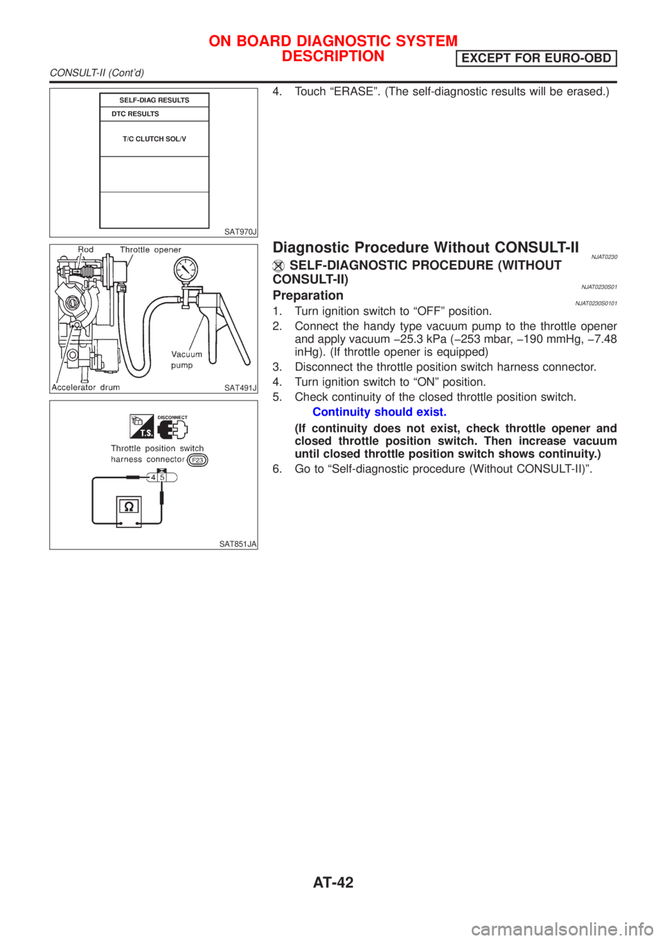
SAT970J
4. Touch ªERASEº. (The self-diagnostic results will be erased.)
SAT491J
SAT851JA
Diagnostic Procedure Without CONSULT-IINJAT0230SELF-DIAGNOSTIC PROCEDURE (WITHOUT
CONSULT-II)
NJAT0230S01PreparationNJAT0230S01011. Turn ignition switch to ªOFFº position.
2. Connect the handy type vacuum pump to the throttle opener
and apply vacuum þ25.3 kPa (þ253 mbar, þ190 mmHg, þ7.48
inHg). (If throttle opener is equipped)
3. Disconnect the throttle position switch harness connector.
4. Turn ignition switch to ªONº position.
5. Check continuity of the closed throttle position switch.
Continuity should exist.
(If continuity does not exist, check throttle opener and
closed throttle position switch. Then increase vacuum
until closed throttle position switch shows continuity.)
6. Go to ªSelf-diagnostic procedure (Without CONSULT-II)º.
ON BOARD DIAGNOSTIC SYSTEM
DESCRIPTION
EXCEPT FOR EURO-OBD
CONSULT-II (Cont'd)
AT-42
Page 1229 of 2493
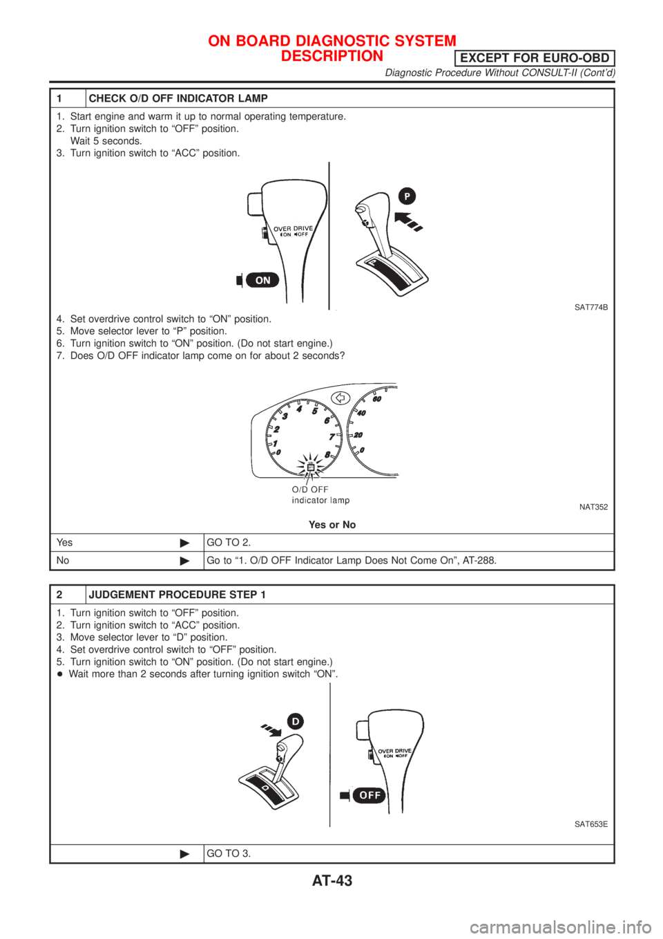
1 CHECK O/D OFF INDICATOR LAMP
1. Start engine and warm it up to normal operating temperature.
2. Turn ignition switch to ªOFFº position.
Wait 5 seconds.
3. Turn ignition switch to ªACCº position.
SAT774B
4. Set overdrive control switch to ªONº position.
5. Move selector lever to ªPº position.
6. Turn ignition switch to ªONº position. (Do not start engine.)
7. Does O/D OFF indicator lamp come on for about 2 seconds?
NAT352
YesorNo
Ye s©GO TO 2.
No©Go to ª1. O/D OFF Indicator Lamp Does Not Come Onº, AT-288.
2 JUDGEMENT PROCEDURE STEP 1
1. Turn ignition switch to ªOFFº position.
2. Turn ignition switch to ªACCº position.
3. Move selector lever to ªDº position.
4. Set overdrive control switch to ªOFFº position.
5. Turn ignition switch to ªONº position. (Do not start engine.)
+Wait more than 2 seconds after turning ignition switch ªONº.
SAT653E
©GO TO 3.
ON BOARD DIAGNOSTIC SYSTEM
DESCRIPTION
EXCEPT FOR EURO-OBD
Diagnostic Procedure Without CONSULT-II (Cont'd)
AT-43
Page 1230 of 2493
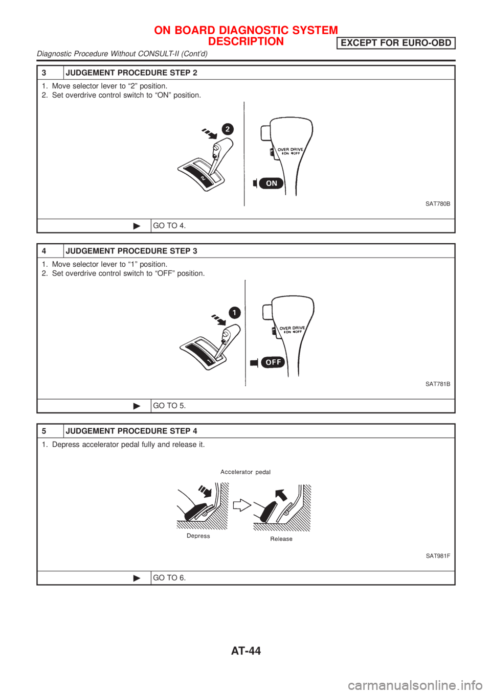
3 JUDGEMENT PROCEDURE STEP 2
1. Move selector lever to ª2º position.
2. Set overdrive control switch to ªONº position.
SAT780B
©GO TO 4.
4 JUDGEMENT PROCEDURE STEP 3
1. Move selector lever to ª1º position.
2. Set overdrive control switch to ªOFFº position.
SAT781B
©GO TO 5.
5 JUDGEMENT PROCEDURE STEP 4
1. Depress accelerator pedal fully and release it.
SAT981F
©GO TO 6.
ON BOARD DIAGNOSTIC SYSTEM
DESCRIPTION
EXCEPT FOR EURO-OBD
Diagnostic Procedure Without CONSULT-II (Cont'd)
AT-44