NISSAN ALMERA N16 2001 Electronic Repair Manual
Manufacturer: NISSAN, Model Year: 2001, Model line: ALMERA N16, Model: NISSAN ALMERA N16 2001Pages: 2493, PDF Size: 66.97 MB
Page 1181 of 2493
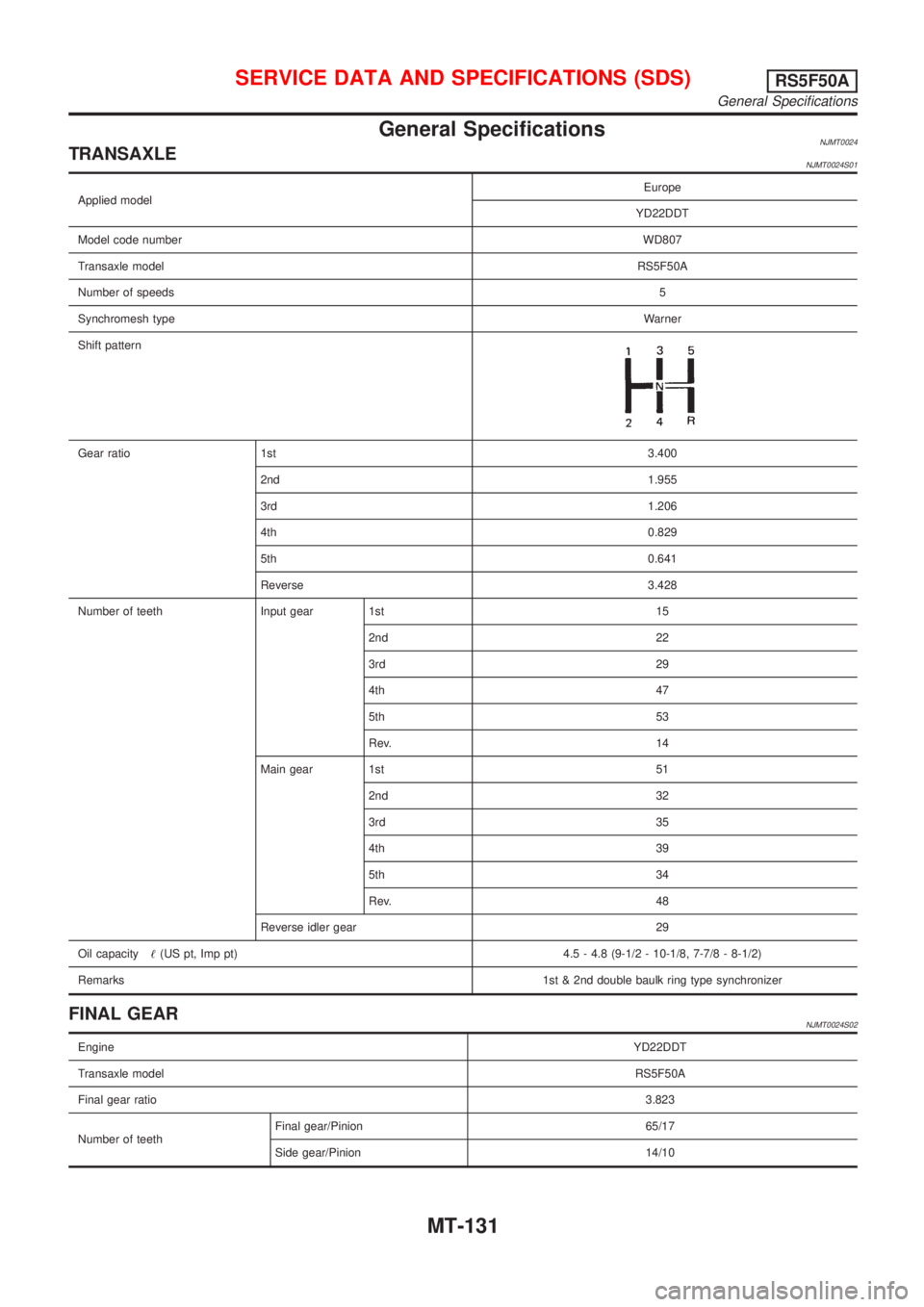
General SpecificationsNJMT0024TRANSAXLENJMT0024S01
Applied modelEurope
YD22DDT
Model code numberWD807
Transaxle modelRS5F50A
Number of speeds5
Synchromesh typeWarner
Shift pattern
Gear ratio 1st3.400
2nd 1.955
3rd 1.206
4th 0.829
5th 0.641
Reverse 3.428
Number of teeth Input gear 1st 15
2nd 22
3rd 29
4th 47
5th 53
Rev. 14
Main gear 1st 51
2nd 32
3rd 35
4th 39
5th 34
Rev. 48
Reverse idler gear 29
Oil capacity!(US pt, Imp pt) 4.5 - 4.8 (9-1/2 - 10-1/8, 7-7/8 - 8-1/2)
Remarks1st & 2nd double baulk ring type synchronizer
FINAL GEARNJMT0024S02
EngineYD22DDT
Transaxle modelRS5F50A
Final gear ratio3.823
Number of teethFinal gear/Pinion 65/17
Side gear/Pinion 14/10
SERVICE DATA AND SPECIFICATIONS (SDS)RS5F50A
General Specifications
MT-131
Page 1182 of 2493
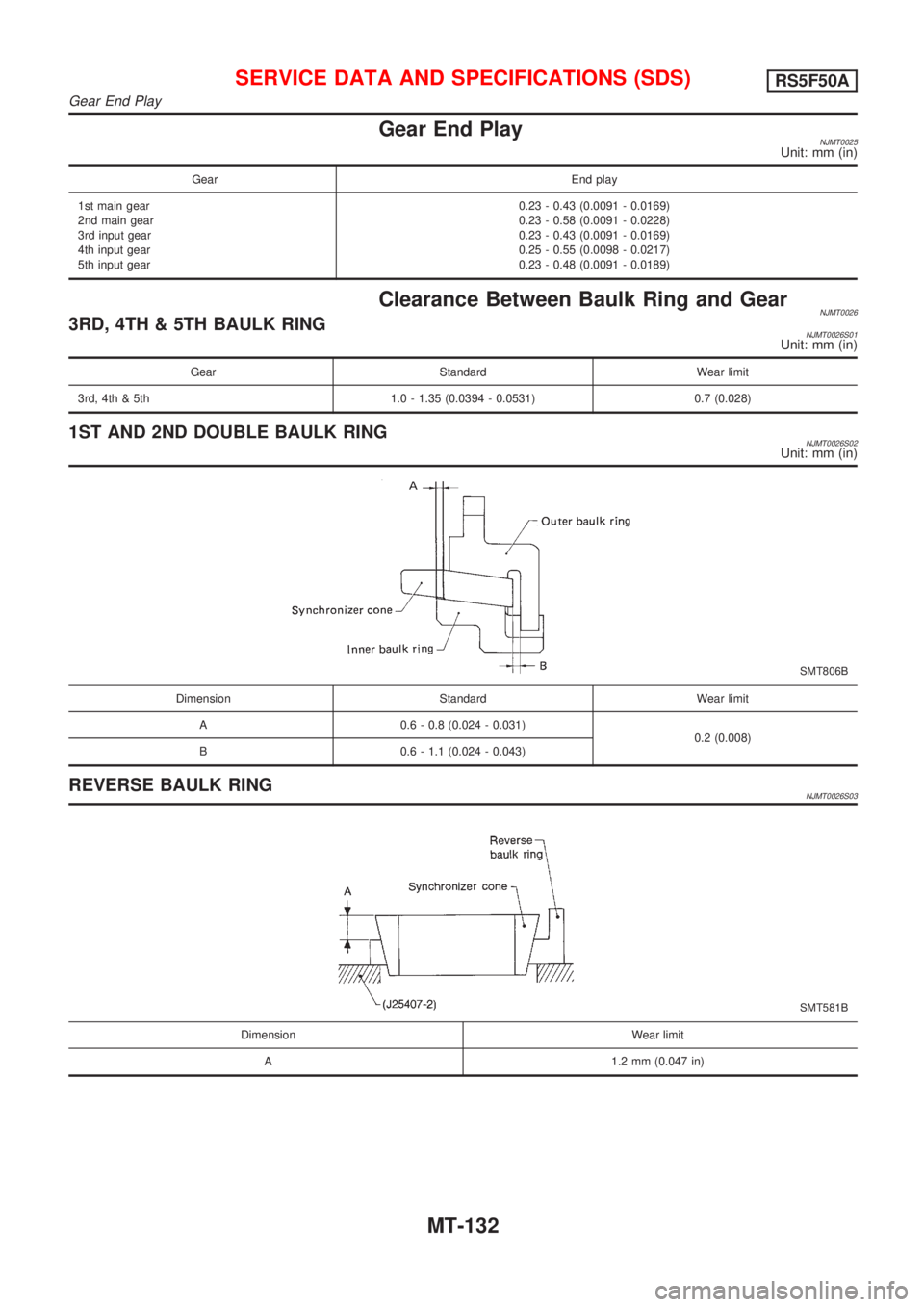
Gear End PlayNJMT0025Unit: mm (in)
Gear End play
1st main gear
2nd main gear
3rd input gear
4th input gear
5th input gear0.23 - 0.43 (0.0091 - 0.0169)
0.23 - 0.58 (0.0091 - 0.0228)
0.23 - 0.43 (0.0091 - 0.0169)
0.25 - 0.55 (0.0098 - 0.0217)
0.23 - 0.48 (0.0091 - 0.0189)
Clearance Between Baulk Ring and GearNJMT00263RD, 4TH & 5TH BAULK RINGNJMT0026S01Unit: mm (in)
Gear Standard Wear limit
3rd, 4th & 5th 1.0 - 1.35 (0.0394 - 0.0531) 0.7 (0.028)
1ST AND 2ND DOUBLE BAULK RINGNJMT0026S02Unit: mm (in)
SMT806B
Dimension Standard Wear limit
A 0.6 - 0.8 (0.024 - 0.031)
0.2 (0.008)
B 0.6 - 1.1 (0.024 - 0.043)
REVERSE BAULK RINGNJMT0026S03
SMT581B
Dimension Wear limit
A 1.2 mm (0.047 in)
SERVICE DATA AND SPECIFICATIONS (SDS)RS5F50A
Gear End Play
MT-132
Page 1183 of 2493
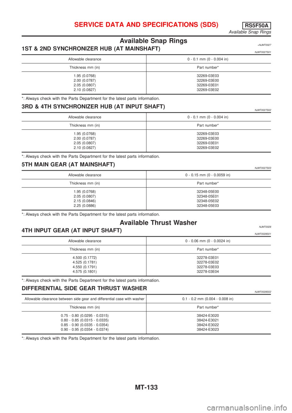
Available Snap Rings=NJMT00271ST & 2ND SYNCHRONIZER HUB (AT MAINSHAFT)NJMT0027S01
Allowable clearance 0 - 0.1 mm (0 - 0.004 in)
Thickness mm (in) Part number*
1.95 (0.0768)
2.00 (0.0787)
2.05 (0.0807)
2.10 (0.0827)32269-03E03
32269-03E00
32269-03E01
32269-03E02
*: Always check with the Parts Department for the latest parts information.
3RD & 4TH SYNCHRONIZER HUB (AT INPUT SHAFT)NJMT0027S02
Allowable clearance 0 - 0.1 mm (0 - 0.004 in)
Thickness mm (in) Part number*
1.95 (0.0768)
2.00 (0.0787)
2.05 (0.0807)
2.10 (0.0827)32269-03E03
32269-03E00
32269-03E01
32269-03E02
*: Always check with the Parts Department for the latest parts information.
5TH MAIN GEAR (AT MAINSHAFT)NJMT0027S03
Allowable clearance 0 - 0.15 mm (0 - 0.0059 in)
Thickness mm (in) Part number*
1.95 (0.0768)
2.05 (0.0807)
2.15 (0.0846)
2.25 (0.0886)32348-05E00
32348-05E01
32348-05E02
32348-05E03
*: Always check with the Parts Department for the latest parts information.
Available Thrust WasherNJMT00284TH INPUT GEAR (AT INPUT SHAFT)NJMT0028S01
Allowable clearance 0 - 0.06 mm (0 - 0.0024 in)
Thickness mm (in) Part number*
4.500 (0.1772)
4.525 (0.1781)
4.550 (0.1791)
4.575 (0.1801)32278-03E01
32278-03E02
32278-03E03
32278-03E04
*: Always check with the Parts Department for the latest parts information.
DIFFERENTIAL SIDE GEAR THRUST WASHERNJMT0028S02
Allowable clearance between side gear and differential case with washer 0.1 - 0.2 mm (0.004 - 0.008 in)
Thickness mm (in) Part number*
0.75 - 0.80 (0.0295 - 0.0315)
0.80 - 0.85 (0.0315 - 0.0335)
0.85 - 0.90 (0.0335 - 0.0354)
0.90 - 0.95 (0.0354 - 0.0374)38424-E3020
38424-E3021
38424-E3022
38424-E3023
*: Always check with the Parts Department for the latest parts information.
SERVICE DATA AND SPECIFICATIONS (SDS)RS5F50A
Available Snap Rings
MT-133
Page 1184 of 2493
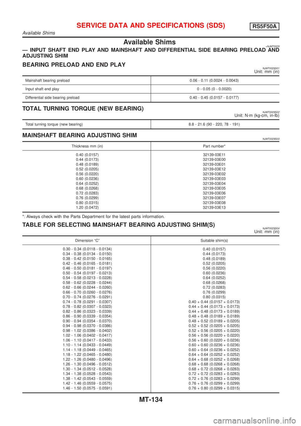
Available Shims=NJMT0029Ð INPUT SHAFT END PLAY AND MAINSHAFT AND DIFFERENTIAL SIDE BEARING PRELOAD AND
ADJUSTING SHIM
BEARING PRELOAD AND END PLAYNJMT0029S01Unit: mm (in)
Mainshaft bearing preload 0.06 - 0.11 (0.0024 - 0.0043)
Input shaft end play0 - 0.05 (0 - 0.0020)
Differential side bearing preload 0.40 - 0.45 (0.0157 - 0.0177)
TOTAL TURNING TORQUE (NEW BEARING)NJMT0029S02Unit: N´m (kg-cm, in-lb)
Total turning torque (new bearing) 8.8 - 21.6 (90 - 220, 78 - 191)
MAINSHAFT BEARING ADJUSTING SHIMNJMT0029S03
Thickness mm (in) Part number*
0.40 (0.0157)
0.44 (0.0173)
0.48 (0.0189)
0.52 (0.0205)
0.56 (0.0220)
0.60 (0.0236)
0.64 (0.0252)
0.68 (0.0268)
0.72 (0.0283)
0.76 (0.0299)
0.80 (0.0315)
1.20 (0.0472)32139-03E11
32139-03E00
32139-03E01
32139-03E12
32139-03E02
32139-03E03
32139-03E04
32139-03E05
32139-03E06
32139-03E07
32139-03E08
32139-03E13
*: Always check with the Parts Department for the latest parts information.
TABLE FOR SELECTING MAINSHAFT BEARING ADJUSTING SHIM(S)NJMT0029S04Unit: mm (in)
Dimension ªCº Suitable shim(s)
0.30 - 0.34 (0.0118 - 0.0134)
0.34 - 0.38 (0.0134 - 0.0150)
0.38 - 0.42 (0.0150 - 0.0165)
0.42 - 0.46 (0.0165 - 0.0181)
0.46 - 0.50 (0.0181 - 0.0197)
0.50 - 0.54 (0.0197 - 0.0213)
0.54 - 0.58 (0.0213 - 0.0228)
0.58 - 0.62 (0.0228 - 0.0244)
0.62 - 0.66 (0.0244 - 0.0260)
0.66 - 0.70 (0.0260 - 0.0276)
0.70 - 0.74 (0.0276 - 0.0291)
0.74 - 0.78 (0.0291 - 0.0307)
0.78 - 0.82 (0.0307 - 0.0323)
0.82 - 0.86 (0.0323 - 0.0339)
0.86 - 0.90 (0.0339 - 0.0354)
0.90 - 0.94 (0.0354 - 0.0370)
0.94 - 0.98 (0.0370 - 0.0386)
0.98 - 1.02 (0.0386 - 0.0402)
1.02 - 1.06 (0.0402 - 0.0417)
1.06 - 1.10 (0.0417 - 0.0433)
1.10 - 1.14 (0.0433 - 0.0449)
1.14 - 1.18 (0.0449 - 0.0465)
1.18 - 1.22 (0.0465 - 0.0480)
1.22 - 1.26 (0.0480 - 0.0496)
1.26 - 1.30 (0.0496 - 0.0512)
1.30 - 1.34 (0.0512 - 0.0528)
1.34 - 1.38 (0.0528 - 0.0543)
1.38 - 1.42 (0.0543 - 0.0559)
1.42 - 1.46 (0.0559 - 0.0575)
1.46 - 1.50 (0.0575 - 0.0591)0.40 (0.0157)
0.44 (0.0173)
0.48 (0.0189)
0.52 (0.0205)
0.56 (0.0220)
0.60 (0.0236)
0.64 (0.0252)
0.68 (0.0268)
0.72 (0.0283)
0.76 (0.0299)
0.80 (0.0315)
0.40 + 0.44 (0.0157 + 0.0173)
0.44 + 0.44 (0.0173 + 0.0173)
0.44 + 0.48 (0.0173 + 0.0189)
0.48 + 0.48 (0.0189 + 0.0189)
0.48 + 0.52 (0.0189 + 0.0205)
0.52 + 0.52 (0.0205 + 0.0205)
0.52 + 0.56 (0.0205 + 0.0220)
0.56 + 0.56 (0.0220 + 0.0220)
0.56 + 0.60 (0.0220 + 0.0236)
0.60 + 0.60 (0.0236 + 0.0236)
0.60 + 0.64 (0.0236 + 0.0252)
0.64 + 0.64 (0.0252 + 0.0252)
0.64 + 0.68 (0.0252 + 0.0268)
0.68 + 0.68 (0.0268 + 0.0268)
0.68 + 0.72 (0.0268 + 0.0283)
0.72 + 0.72 (0.0283 + 0.0283)
0.72 + 0.76 (0.0283 + 0.0299)
0.76 + 0.76 (0.0299 + 0.0299)
0.76 + 0.80 (0.0299 + 0.0315)
SERVICE DATA AND SPECIFICATIONS (SDS)RS5F50A
Available Shims
MT-134
Page 1185 of 2493
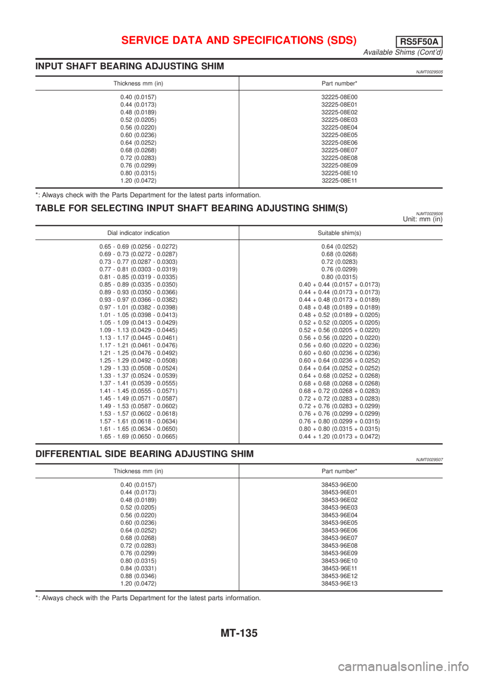
INPUT SHAFT BEARING ADJUSTING SHIMNJMT0029S05
Thickness mm (in) Part number*
0.40 (0.0157)
0.44 (0.0173)
0.48 (0.0189)
0.52 (0.0205)
0.56 (0.0220)
0.60 (0.0236)
0.64 (0.0252)
0.68 (0.0268)
0.72 (0.0283)
0.76 (0.0299)
0.80 (0.0315)
1.20 (0.0472)32225-08E00
32225-08E01
32225-08E02
32225-08E03
32225-08E04
32225-08E05
32225-08E06
32225-08E07
32225-08E08
32225-08E09
32225-08E10
32225-08E11
*: Always check with the Parts Department for the latest parts information.
TABLE FOR SELECTING INPUT SHAFT BEARING ADJUSTING SHIM(S)NJMT0029S06Unit: mm (in)
Dial indicator indication Suitable shim(s)
0.65 - 0.69 (0.0256 - 0.0272)
0.69 - 0.73 (0.0272 - 0.0287)
0.73 - 0.77 (0.0287 - 0.0303)
0.77 - 0.81 (0.0303 - 0.0319)
0.81 - 0.85 (0.0319 - 0.0335)
0.85 - 0.89 (0.0335 - 0.0350)
0.89 - 0.93 (0.0350 - 0.0366)
0.93 - 0.97 (0.0366 - 0.0382)
0.97 - 1.01 (0.0382 - 0.0398)
1.01 - 1.05 (0.0398 - 0.0413)
1.05 - 1.09 (0.0413 - 0.0429)
1.09 - 1.13 (0.0429 - 0.0445)
1.13 - 1.17 (0.0445 - 0.0461)
1.17 - 1.21 (0.0461 - 0.0476)
1.21 - 1.25 (0.0476 - 0.0492)
1.25 - 1.29 (0.0492 - 0.0508)
1.29 - 1.33 (0.0508 - 0.0524)
1.33 - 1.37 (0.0524 - 0.0539)
1.37 - 1.41 (0.0539 - 0.0555)
1.41 - 1.45 (0.0555 - 0.0571)
1.45 - 1.49 (0.0571 - 0.0587)
1.49 - 1.53 (0.0587 - 0.0602)
1.53 - 1.57 (0.0602 - 0.0618)
1.57 - 1.61 (0.0618 - 0.0634)
1.61 - 1.65 (0.0634 - 0.0650)
1.65 - 1.69 (0.0650 - 0.0665)0.64 (0.0252)
0.68 (0.0268)
0.72 (0.0283)
0.76 (0.0299)
0.80 (0.0315)
0.40 + 0.44 (0.0157 + 0.0173)
0.44 + 0.44 (0.0173 + 0.0173)
0.44 + 0.48 (0.0173 + 0.0189)
0.48 + 0.48 (0.0189 + 0.0189)
0.48 + 0.52 (0.0189 + 0.0205)
0.52 + 0.52 (0.0205 + 0.0205)
0.52 + 0.56 (0.0205 + 0.0220)
0.56 + 0.56 (0.0220 + 0.0220)
0.56 + 0.60 (0.0220 + 0.0236)
0.60 + 0.60 (0.0236 + 0.0236)
0.60 + 0.64 (0.0236 + 0.0252)
0.64 + 0.64 (0.0252 + 0.0252)
0.64 + 0.68 (0.0252 + 0.0268)
0.68 + 0.68 (0.0268 + 0.0268)
0.68 + 0.72 (0.0268 + 0.0283)
0.72 + 0.72 (0.0283 + 0.0283)
0.72 + 0.76 (0.0283 + 0.0299)
0.76 + 0.76 (0.0299 + 0.0299)
0.76 + 0.80 (0.0299 + 0.0315)
0.80 + 0.80 (0.0315 + 0.0315)
0.44 + 1.20 (0.0173 + 0.0472)
DIFFERENTIAL SIDE BEARING ADJUSTING SHIMNJMT0029S07
Thickness mm (in) Part number*
0.40 (0.0157)
0.44 (0.0173)
0.48 (0.0189)
0.52 (0.0205)
0.56 (0.0220)
0.60 (0.0236)
0.64 (0.0252)
0.68 (0.0268)
0.72 (0.0283)
0.76 (0.0299)
0.80 (0.0315)
0.84 (0.0331)
0.88 (0.0346)
1.20 (0.0472)38453-96E00
38453-96E01
38453-96E02
38453-96E03
38453-96E04
38453-96E05
38453-96E06
38453-96E07
38453-96E08
38453-96E09
38453-96E10
38453-96E11
38453-96E12
38453-96E13
*: Always check with the Parts Department for the latest parts information.
SERVICE DATA AND SPECIFICATIONS (SDS)RS5F50A
Available Shims (Cont'd)
MT-135
Page 1186 of 2493
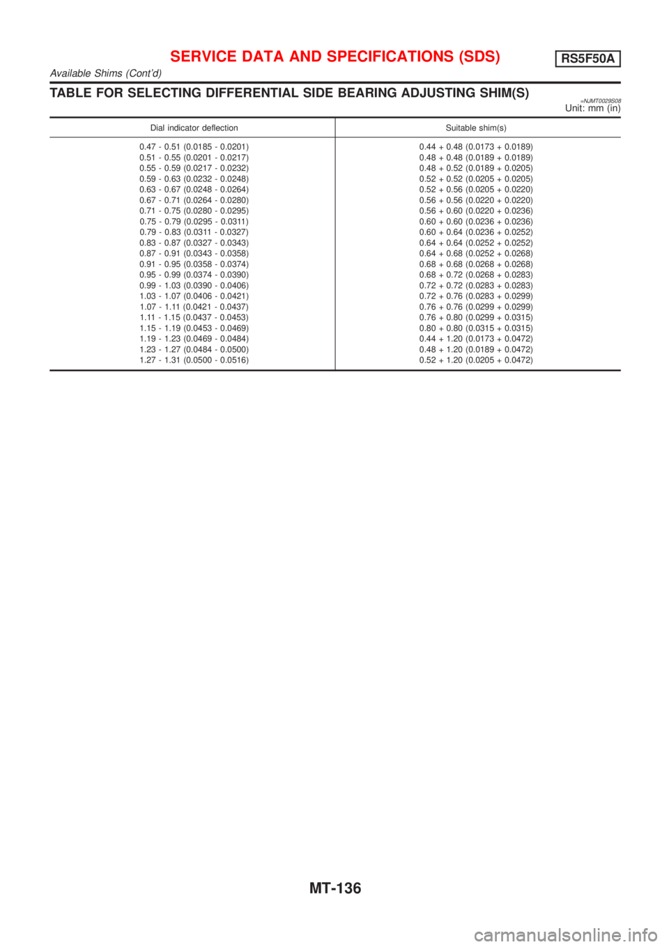
TABLE FOR SELECTING DIFFERENTIAL SIDE BEARING ADJUSTING SHIM(S)=NJMT0029S08Unit: mm (in)
Dial indicator deflection Suitable shim(s)
0.47 - 0.51 (0.0185 - 0.0201)
0.51 - 0.55 (0.0201 - 0.0217)
0.55 - 0.59 (0.0217 - 0.0232)
0.59 - 0.63 (0.0232 - 0.0248)
0.63 - 0.67 (0.0248 - 0.0264)
0.67 - 0.71 (0.0264 - 0.0280)
0.71 - 0.75 (0.0280 - 0.0295)
0.75 - 0.79 (0.0295 - 0.0311)
0.79 - 0.83 (0.0311 - 0.0327)
0.83 - 0.87 (0.0327 - 0.0343)
0.87 - 0.91 (0.0343 - 0.0358)
0.91 - 0.95 (0.0358 - 0.0374)
0.95 - 0.99 (0.0374 - 0.0390)
0.99 - 1.03 (0.0390 - 0.0406)
1.03 - 1.07 (0.0406 - 0.0421)
1.07 - 1.11 (0.0421 - 0.0437)
1.11 - 1.15 (0.0437 - 0.0453)
1.15 - 1.19 (0.0453 - 0.0469)
1.19 - 1.23 (0.0469 - 0.0484)
1.23 - 1.27 (0.0484 - 0.0500)
1.27 - 1.31 (0.0500 - 0.0516)0.44 + 0.48 (0.0173 + 0.0189)
0.48 + 0.48 (0.0189 + 0.0189)
0.48 + 0.52 (0.0189 + 0.0205)
0.52 + 0.52 (0.0205 + 0.0205)
0.52 + 0.56 (0.0205 + 0.0220)
0.56 + 0.56 (0.0220 + 0.0220)
0.56 + 0.60 (0.0220 + 0.0236)
0.60 + 0.60 (0.0236 + 0.0236)
0.60 + 0.64 (0.0236 + 0.0252)
0.64 + 0.64 (0.0252 + 0.0252)
0.64 + 0.68 (0.0252 + 0.0268)
0.68 + 0.68 (0.0268 + 0.0268)
0.68 + 0.72 (0.0268 + 0.0283)
0.72 + 0.72 (0.0283 + 0.0283)
0.72 + 0.76 (0.0283 + 0.0299)
0.76 + 0.76 (0.0299 + 0.0299)
0.76 + 0.80 (0.0299 + 0.0315)
0.80 + 0.80 (0.0315 + 0.0315)
0.44 + 1.20 (0.0173 + 0.0472)
0.48 + 1.20 (0.0189 + 0.0472)
0.52 + 1.20 (0.0205 + 0.0472)
SERVICE DATA AND SPECIFICATIONS (SDS)RS5F50A
Available Shims (Cont'd)
MT-136
Page 1187 of 2493
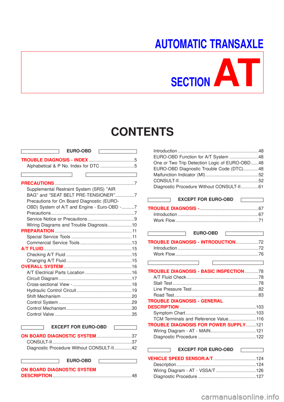
AUTOMATIC TRANSAXLE
SECTION
AT
CONTENTS
EURO-OBD
TROUBLE DIAGNOSIS - INDEX....................................5
Alphabetical & P No. Index for DTC ...........................5
PRECAUTIONS...............................................................7
Supplemental Restraint System (SRS)²AIR
BAG²and²SEAT BELT PRE-TENSIONER²...............7
Precautions for On Board Diagnostic (EURO-
OBD) System of A/T and Engine - Euro-OBD - ..........7
Precautions ..................................................................7
Service Notice or Precautions .....................................9
Wiring Diagrams and Trouble Diagnosis ...................10
PREPARATION............................................................. 11
Special Service Tools ................................................ 11
Commercial Service Tools .........................................13
A/T FLUID......................................................................15
Checking A/T Fluid ....................................................15
Changing A/T Fluid ....................................................15
OVERALL SYSTEM......................................................16
A/T Electrical Parts Location .....................................16
Circuit Diagram ..........................................................17
Cross-sectional View - ...............................................18
Hydraulic Control Circuit ............................................19
Shift Mechanism ........................................................20
Control System ..........................................................29
Control Mechanism ....................................................30
Control Valve .............................................................35
EXCEPT FOR EURO-OBD
ON BOARD DIAGNOSTIC SYSTEM............................37
CONSULT-II ...............................................................37
Diagnostic Procedure Without CONSULT-II ..............42
EURO-OBD
ON BOARD DIAGNOSTIC SYSTEM
DESCRIPTION...............................................................48Introduction ................................................................48
EURO-OBD Function for A/T System .......................48
One or Two Trip Detection Logic of EURO-OBD ......48
EURO-OBD Diagnostic Trouble Code (DTC)............48
Malfunction Indicator (MI) ..........................................52
CONSULT-II ...............................................................52
Diagnostic Procedure Without CONSULT-II ..............61
EXCEPT FOR EURO-OBD
TROUBLE DIAGNOSIS -...............................................67
Introduction ................................................................67
Work Flow ..................................................................71
EURO-OBD
TROUBLE DIAGNOSIS - INTRODUCTION..................72
Introduction ................................................................72
Work Flow ..................................................................76
TROUBLE DIAGNOSIS - BASIC INSPECTION...........78
A/T Fluid Check .........................................................78
Stall Test ....................................................................78
Line Pressure Test .....................................................82
Road Test...................................................................83
TROUBLE DIAGNOSIS - GENERAL
DESCRIPTION.............................................................103
Symptom Chart ........................................................103
TCM Terminals and Reference Value...................... 116
TROUBLE DIAGNOSIS FOR POWER SUPPLY........121
Wiring Diagram - AT - MAIN ....................................121
Diagnostic Procedure ..............................................122
EXCEPT FOR EURO-OBD
VEHICLE SPEED SENSOR.A/T..................................124
Description ...............................................................124
Wiring Diagram - AT - VSSA/T ................................126
Diagnostic Procedure ..............................................127
Page 1188 of 2493
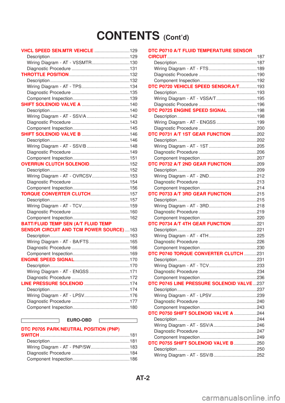
VHCL SPEED SEN.MTR VEHICLE............................129
Description ...............................................................129
Wiring Diagram - AT - VSSMTR ..............................130
Diagnostic Procedure ..............................................131
THROTTLE POSITION................................................132
Description ...............................................................132
Wiring Diagram - AT - TPS ......................................134
Diagnostic Procedure ..............................................135
Component Inspection .............................................139
SHIFT SOLENOID VALVE A......................................140
Description ...............................................................140
Wiring Diagram - AT - SSV/A ..................................142
Diagnostic Procedure ..............................................143
Component Inspection .............................................145
SHIFT SOLENOID VALVE B......................................146
Description ...............................................................146
Wiring Diagram - AT - SSV/B ..................................148
Diagnostic Procedure ..............................................149
Component Inspection .............................................151
OVERRUN CLUTCH SOLENOID................................152
Description ...............................................................152
Wiring Diagram - AT - OVRCSV..............................153
Diagnostic Procedure ..............................................154
Component Inspection .............................................156
TORQUE CONVERTER CLUTCH...............................157
Description ...............................................................157
Wiring Diagram - AT - TCV......................................159
Diagnostic Procedure ..............................................160
Component Inspection .............................................162
BATT/FLUID TEMP SEN (A/T FLUID TEMP
SENSOR CIRCUIT AND TCM POWER SOURCE)....163
Description ...............................................................163
Wiring Diagram - AT - BA/FTS ................................165
Diagnostic Procedure ..............................................166
Component Inspection .............................................169
ENGINE SPEED SIGNAL............................................170
Description ...............................................................170
Wiring Diagram - AT - ENGSS ................................171
Diagnostic Procedure ..............................................172
LINE PRESSURE SOLENOID....................................174
Description ...............................................................174
Wiring Diagram - AT - LPSV....................................176
Diagnostic Procedure ..............................................177
Component Inspection .............................................180
EURO-OBD
DTC P0705 PARK/NEUTRAL POSITION (PNP)
SWITCH.......................................................................181
Description ...............................................................181
Wiring Diagram - AT - PNP/SW...............................183
Diagnostic Procedure ..............................................184
Component Inspection .............................................186DTC P0710 A/T FLUID TEMPERATURE SENSOR
CIRCUIT.......................................................................187
Description ...............................................................187
Wiring Diagram - AT - FTS ......................................189
Diagnostic Procedure ..............................................190
Component Inspection .............................................192
DTC P0720 VEHICLE SPEED SENSOR.A/T..............193
Description ...............................................................193
Wiring Diagram - AT - VSSA/T ................................195
Diagnostic Procedure ..............................................196
DTC P0725 ENGINE SPEED SIGNAL.......................198
Description ...............................................................198
Wiring Diagram - AT - ENGSS ................................199
Diagnostic Procedure ..............................................200
DTC P0731 A/T 1ST GEAR FUNCTION....................202
Description ...............................................................202
Wiring Diagram - AT - 1ST ......................................205
Diagnostic Procedure ..............................................206
Component Inspection .............................................207
DTC P0732 A/T 2ND GEAR FUNCTION....................209
Description ...............................................................209
Wiring Diagram - AT - 2ND......................................212
Diagnostic Procedure ..............................................213
Component Inspection .............................................214
DTC P0733 A/T 3RD GEAR FUNCTION....................215
Description ...............................................................215
Wiring Diagram - AT - 3RD......................................218
Diagnostic Procedure ..............................................219
Component Inspection .............................................220
DTC P0734 A/T 4TH GEAR FUNCTION....................221
Description ...............................................................221
Wiring Diagram - AT - 4TH ......................................225
Diagnostic Procedure ..............................................226
Component Inspection .............................................230
DTC P0740 TORQUE CONVERTER CLUTCH..........231
Description ...............................................................231
Wiring Diagram - AT - TCV......................................233
Diagnostic Procedure ..............................................234
Component Inspection .............................................236
DTC P0745 LINE PRESSURE SOLENOID VALVE...237
Description ...............................................................237
Wiring Diagram - AT - LPSV....................................239
Diagnostic Procedure ..............................................240
Component Inspection .............................................243
DTC P0750 SHIFT SOLENOID VALVE A..................244
Description ...............................................................244
Wiring Diagram - AT - SSV/A ..................................246
Diagnostic Procedure ..............................................247
Component Inspection .............................................249
DTC P0755 SHIFT SOLENOID VALVE B..................250
Description ...............................................................250
Wiring Diagram - AT - SSV/B ..................................252
CONTENTS(Cont'd)
AT-2
Page 1189 of 2493
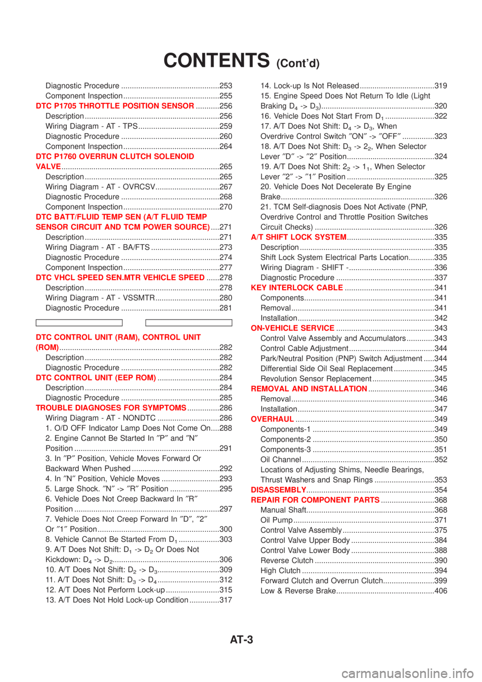
Diagnostic Procedure ..............................................253
Component Inspection .............................................255
DTC P1705 THROTTLE POSITION SENSOR...........256
Description ...............................................................256
Wiring Diagram - AT - TPS ......................................259
Diagnostic Procedure ..............................................260
Component Inspection .............................................264
DTC P1760 OVERRUN CLUTCH SOLENOID
VALVE..........................................................................265
Description ...............................................................265
Wiring Diagram - AT - OVRCSV..............................267
Diagnostic Procedure ..............................................268
Component Inspection .............................................270
DTC BATT/FLUID TEMP SEN (A/T FLUID TEMP
SENSOR CIRCUIT AND TCM POWER SOURCE)....271
Description ...............................................................271
Wiring Diagram - AT - BA/FTS ................................273
Diagnostic Procedure ..............................................274
Component Inspection .............................................277
DTC VHCL SPEED SEN.MTR VEHICLE SPEED......278
Description ...............................................................278
Wiring Diagram - AT - VSSMTR ..............................280
Diagnostic Procedure ..............................................281
DTC CONTROL UNIT (RAM), CONTROL UNIT
(ROM)...........................................................................282
Description ...............................................................282
Diagnostic Procedure ..............................................282
DTC CONTROL UNIT (EEP ROM).............................284
Description ...............................................................284
Diagnostic Procedure ..............................................285
TROUBLE DIAGNOSES FOR SYMPTOMS...............286
Wiring Diagram - AT - NONDTC .............................286
1. O/D OFF Indicator Lamp Does Not Come On....288
2. Engine Cannot Be Started In²P²and²N²
Position ....................................................................291
3. In²P²Position, Vehicle Moves Forward Or
Backward When Pushed .........................................292
4. In²N²Position, Vehicle Moves ...........................293
5. Large Shock.²N²->²R²Position .......................295
6. Vehicle Does Not Creep Backward In²R²
Position ....................................................................297
7. Vehicle Does Not Creep Forward In²D²,²2²
Or²1²Position .........................................................300
8. Vehicle Cannot Be Started From D
1...................303
9. A/T Does Not Shift: D
1-> D2Or Does Not
Kickdown: D
4-> D2..................................................306
10. A/T Does Not Shift: D
2-> D3.............................309
11. A/T Does Not Shift: D
3-> D4.............................312
12. A/T Does Not Perform Lock-up .........................315
13. A/T Does Not Hold Lock-up Condition ..............31714. Lock-up Is Not Released ...................................319
15. Engine Speed Does Not Return To Idle (Light
Braking D
4-> D3).....................................................320
16. Vehicle Does Not Start From D
1.......................322
17. A/T Does Not Shift: D
4-> D3, When
Overdrive Control Switch²ON²->²OFF²...............323
18. A/T Does Not Shift: D
3-> 22, When Selector
Lever²D²->²2²Position.........................................324
19. A/T Does Not Shift: 2
2-> 11, When Selector
Lever²2²->²1²Position .........................................325
20. Vehicle Does Not Decelerate By Engine
Brake........................................................................326
21. TCM Self-diagnosis Does Not Activate (PNP,
Overdrive Control and Throttle Position Switches
Circuit Checks) ........................................................326
A/T SHIFT LOCK SYSTEM.........................................335
Description ...............................................................335
Shift Lock System Electrical Parts Location............335
Wiring Diagram - SHIFT -........................................336
Diagnostic Procedure ..............................................337
KEY INTERLOCK CABLE..........................................341
Components.............................................................341
Removal ...................................................................341
Installation ................................................................342
ON-VEHICLE SERVICE..............................................343
Control Valve Assembly and Accumulators .............343
Control Cable Adjustment ........................................344
Park/Neutral Position (PNP) Switch Adjustment .....344
Differential Side Oil Seal Replacement ...................345
Revolution Sensor Replacement .............................345
REMOVAL AND INSTALLATION...............................346
Removal ...................................................................346
Installation ................................................................347
OVERHAUL.................................................................349
Components-1 .........................................................349
Components-2 .........................................................350
Components-3 .........................................................351
Oil Channel ..............................................................352
Locations of Adjusting Shims, Needle Bearings,
Thrust Washers and Snap Rings ............................353
DISASSEMBLY............................................................354
REPAIR FOR COMPONENT PARTS.........................368
Manual Shaft............................................................368
Oil Pump ..................................................................371
Control Valve Assembly ...........................................375
Control Valve Upper Body .......................................384
Control Valve Lower Body .......................................388
Reverse Clutch ........................................................390
High Clutch ..............................................................394
Forward Clutch and Overrun Clutch........................399
Low & Reverse Brake..............................................406
CONTENTS(Cont'd)
AT-3
Page 1190 of 2493
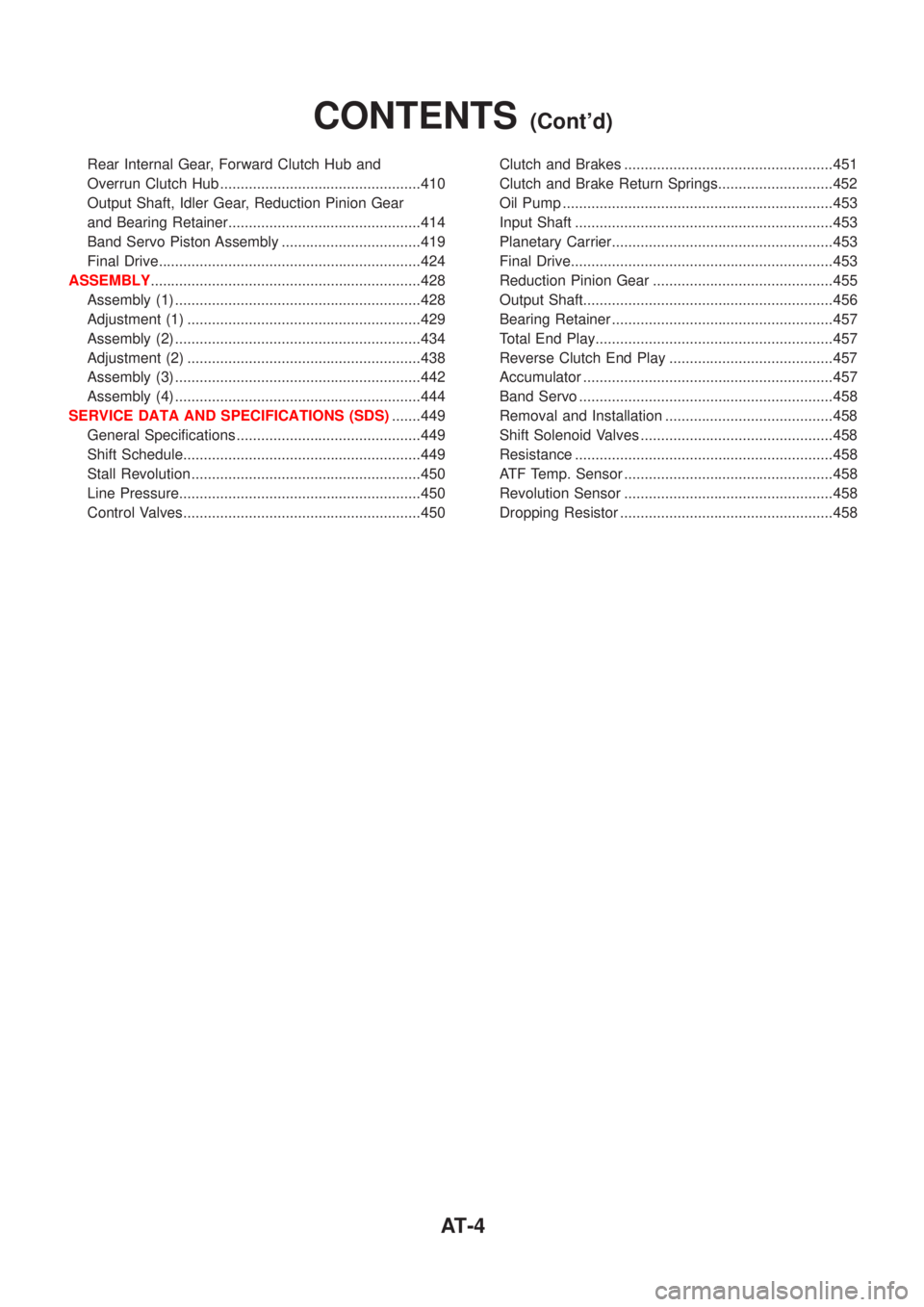
Rear Internal Gear, Forward Clutch Hub and
Overrun Clutch Hub .................................................410
Output Shaft, Idler Gear, Reduction Pinion Gear
and Bearing Retainer...............................................414
Band Servo Piston Assembly ..................................419
Final Drive................................................................424
ASSEMBLY..................................................................428
Assembly (1) ............................................................428
Adjustment (1) .........................................................429
Assembly (2) ............................................................434
Adjustment (2) .........................................................438
Assembly (3) ............................................................442
Assembly (4) ............................................................444
SERVICE DATA AND SPECIFICATIONS (SDS).......449
General Specifications .............................................449
Shift Schedule..........................................................449
Stall Revolution ........................................................450
Line Pressure...........................................................450
Control Valves..........................................................450Clutch and Brakes ...................................................451
Clutch and Brake Return Springs............................452
Oil Pump ..................................................................453
Input Shaft ...............................................................453
Planetary Carrier......................................................453
Final Drive................................................................453
Reduction Pinion Gear ............................................455
Output Shaft.............................................................456
Bearing Retainer ......................................................457
Total End Play..........................................................457
Reverse Clutch End Play ........................................457
Accumulator .............................................................457
Band Servo ..............................................................458
Removal and Installation .........................................458
Shift Solenoid Valves ...............................................458
Resistance ...............................................................458
ATF Temp. Sensor ...................................................458
Revolution Sensor ...................................................458
Dropping Resistor ....................................................458
CONTENTS(Cont'd)
AT-4