NISSAN ALMERA N16 2001 Electronic Repair Manual
Manufacturer: NISSAN, Model Year: 2001, Model line: ALMERA N16, Model: NISSAN ALMERA N16 2001Pages: 2493, PDF Size: 66.97 MB
Page 1891 of 2493
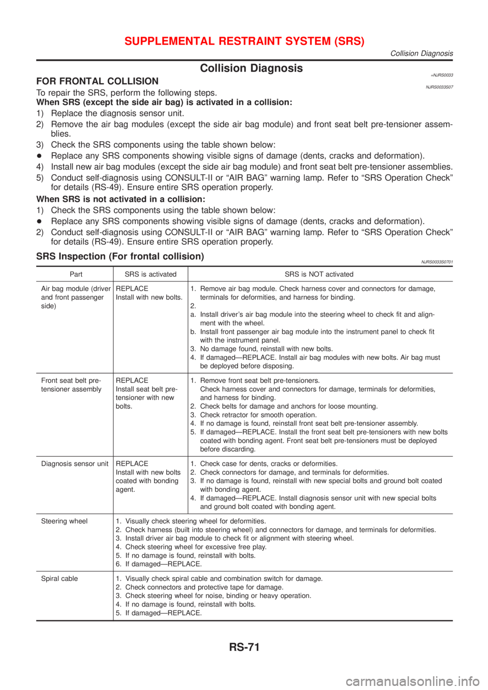
Collision Diagnosis=NJRS0033FOR FRONTAL COLLISIONNJRS0033S07To repair the SRS, perform the following steps.
When SRS (except the side air bag) is activated in a collision:
1) Replace the diagnosis sensor unit.
2) Remove the air bag modules (except the side air bag module) and front seat belt pre-tensioner assem-
blies.
3) Check the SRS components using the table shown below:
+Replace any SRS components showing visible signs of damage (dents, cracks and deformation).
4) Install new air bag modules (except the side air bag module) and front seat belt pre-tensioner assemblies.
5) Conduct self-diagnosis using CONSULT-II or ªAIR BAGº warning lamp. Refer to ªSRS Operation Checkº
for details (RS-49). Ensure entire SRS operation properly.
When SRS is not activated in a collision:
1) Check the SRS components using the table shown below:
+Replace any SRS components showing visible signs of damage (dents, cracks and deformation).
2) Conduct self-diagnosis using CONSULT-II or ªAIR BAGº warning lamp. Refer to ªSRS Operation Checkº
for details (RS-49). Ensure entire SRS operation properly.
SRS Inspection (For frontal collision)NJRS0033S0701
Part SRS is activated SRS is NOT activated
Air bag module (driver
and front passenger
side)REPLACE
Install with new bolts.1. Remove air bag module. Check harness cover and connectors for damage,
terminals for deformities, and harness for binding.
2.
a. Install driver's air bag module into the steering wheel to check fit and align-
ment with the wheel.
b. Install front passenger air bag module into the instrument panel to check fit
with the instrument panel.
3. No damage found, reinstall with new bolts.
4. If damagedÐREPLACE. Install air bag modules with new bolts. Air bag must
be deployed before disposing.
Front seat belt pre-
tensioner assemblyREPLACE
Install seat belt pre-
tensioner with new
bolts.1. Remove front seat belt pre-tensioners.
Check harness cover and connectors for damage, terminals for deformities,
and harness for binding.
2. Check belts for damage and anchors for loose mounting.
3. Check retractor for smooth operation.
4. If no damage is found, reinstall front seat belt pre-tensioner assembly.
5. If damagedÐREPLACE. Install the front seat belt pre-tensioners with new bolts
coated with bonding agent. Front seat belt pre-tensioners must be deployed
before discarding.
Diagnosis sensor unit REPLACE
Install with new bolts
coated with bonding
agent.1. Check case for dents, cracks or deformities.
2. Check connectors for damage, and terminals for deformities.
3. If no damage is found, reinstall with new special bolts and ground bolt coated
with bonding agent.
4. If damagedÐREPLACE. Install diagnosis sensor unit with new special bolts
and ground bolt coated with bonding agent.
Steering wheel 1. Visually check steering wheel for deformities.
2. Check harness (built into steering wheel) and connectors for damage, and terminals for deformities.
3. Install driver air bag module to check fit or alignment with steering wheel.
4. Check steering wheel for excessive free play.
5. If no damage is found, reinstall with bolts.
6. If damagedÐREPLACE.
Spiral cable 1. Visually check spiral cable and combination switch for damage.
2. Check connectors and protective tape for damage.
3. Check steering wheel for noise, binding or heavy operation.
4. If no damage is found, reinstall with bolts.
5. If damagedÐREPLACE.
SUPPLEMENTAL RESTRAINT SYSTEM (SRS)
Collision Diagnosis
RS-71
Page 1892 of 2493
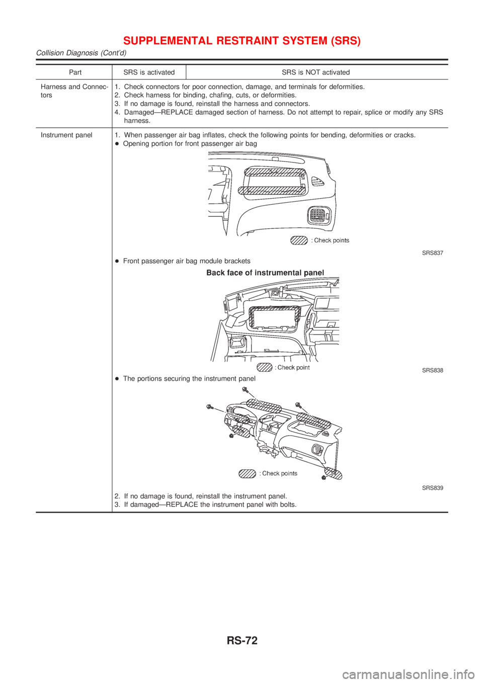
Part SRS is activated SRS is NOT activated
Harness and Connec-
tors1. Check connectors for poor connection, damage, and terminals for deformities.
2. Check harness for binding, chafing, cuts, or deformities.
3. If no damage is found, reinstall the harness and connectors.
4. DamagedÐREPLACE damaged section of harness. Do not attempt to repair, splice or modify any SRS
harness.
Instrument panel 1. When passenger air bag inflates, check the following points for bending, deformities or cracks.
+Opening portion for front passenger air bag
SRS837
+Front passenger air bag module brackets
SRS838
+The portions securing the instrument panel
SRS839
2. If no damage is found, reinstall the instrument panel.
3. If damagedÐREPLACE the instrument panel with bolts.
SUPPLEMENTAL RESTRAINT SYSTEM (SRS)
Collision Diagnosis (Cont'd)
RS-72
Page 1893 of 2493
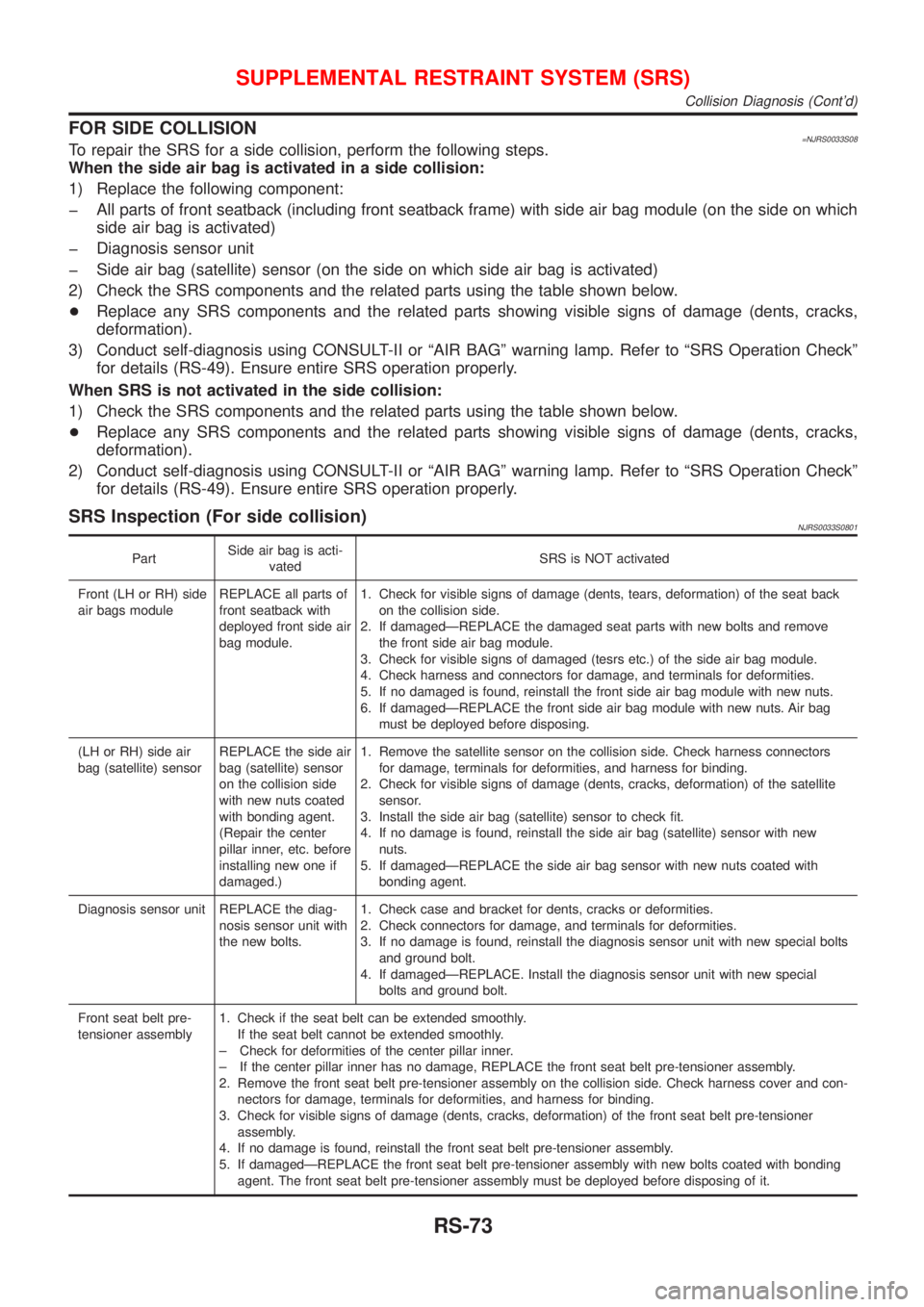
FOR SIDE COLLISION=NJRS0033S08To repair the SRS for a side collision, perform the following steps.
When the side air bag is activated in a side collision:
1) Replace the following component:
þ All parts of front seatback (including front seatback frame) with side air bag module (on the side on which
side air bag is activated)
þ Diagnosis sensor unit
þ Side air bag (satellite) sensor (on the side on which side air bag is activated)
2) Check the SRS components and the related parts using the table shown below.
+Replace any SRS components and the related parts showing visible signs of damage (dents, cracks,
deformation).
3) Conduct self-diagnosis using CONSULT-II or ªAIR BAGº warning lamp. Refer to ªSRS Operation Checkº
for details (RS-49). Ensure entire SRS operation properly.
When SRS is not activated in the side collision:
1) Check the SRS components and the related parts using the table shown below.
+Replace any SRS components and the related parts showing visible signs of damage (dents, cracks,
deformation).
2) Conduct self-diagnosis using CONSULT-II or ªAIR BAGº warning lamp. Refer to ªSRS Operation Checkº
for details (RS-49). Ensure entire SRS operation properly.
SRS Inspection (For side collision)NJRS0033S0801
PartSide air bag is acti-
vatedSRS is NOT activated
Front (LH or RH) side
air bags moduleREPLACE all parts of
front seatback with
deployed front side air
bag module.1. Check for visible signs of damage (dents, tears, deformation) of the seat back
on the collision side.
2. If damagedÐREPLACE the damaged seat parts with new bolts and remove
the front side air bag module.
3. Check for visible signs of damaged (tesrs etc.) of the side air bag module.
4. Check harness and connectors for damage, and terminals for deformities.
5. If no damaged is found, reinstall the front side air bag module with new nuts.
6. If damagedÐREPLACE the front side air bag module with new nuts. Air bag
must be deployed before disposing.
(LH or RH) side air
bag (satellite) sensorREPLACE the side air
bag (satellite) sensor
on the collision side
with new nuts coated
with bonding agent.
(Repair the center
pillar inner, etc. before
installing new one if
damaged.)1. Remove the satellite sensor on the collision side. Check harness connectors
for damage, terminals for deformities, and harness for binding.
2. Check for visible signs of damage (dents, cracks, deformation) of the satellite
sensor.
3. Install the side air bag (satellite) sensor to check fit.
4. If no damage is found, reinstall the side air bag (satellite) sensor with new
nuts.
5. If damagedÐREPLACE the side air bag sensor with new nuts coated with
bonding agent.
Diagnosis sensor unit REPLACE the diag-
nosis sensor unit with
the new bolts.1. Check case and bracket for dents, cracks or deformities.
2. Check connectors for damage, and terminals for deformities.
3. If no damage is found, reinstall the diagnosis sensor unit with new special bolts
and ground bolt.
4. If damagedÐREPLACE. Install the diagnosis sensor unit with new special
bolts and ground bolt.
Front seat belt pre-
tensioner assembly1. Check if the seat belt can be extended smoothly.
If the seat belt cannot be extended smoothly.
± Check for deformities of the center pillar inner.
± If the center pillar inner has no damage, REPLACE the front seat belt pre-tensioner assembly.
2. Remove the front seat belt pre-tensioner assembly on the collision side. Check harness cover and con-
nectors for damage, terminals for deformities, and harness for binding.
3. Check for visible signs of damage (dents, cracks, deformation) of the front seat belt pre-tensioner
assembly.
4. If no damage is found, reinstall the front seat belt pre-tensioner assembly.
5. If damagedÐREPLACE the front seat belt pre-tensioner assembly with new bolts coated with bonding
agent. The front seat belt pre-tensioner assembly must be deployed before disposing of it.
SUPPLEMENTAL RESTRAINT SYSTEM (SRS)
Collision Diagnosis (Cont'd)
RS-73
Page 1894 of 2493
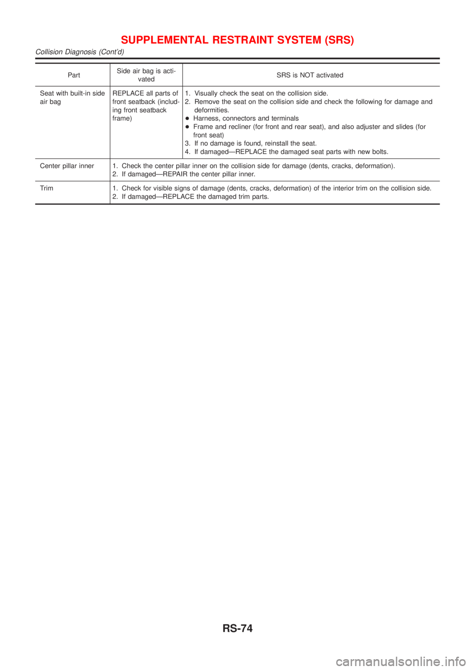
PartSide air bag is acti-
vatedSRS is NOT activated
Seat with built-in side
air bagREPLACE all parts of
front seatback (includ-
ing front seatback
frame)1. Visually check the seat on the collision side.
2. Remove the seat on the collision side and check the following for damage and
deformities.
+Harness, connectors and terminals
+Frame and recliner (for front and rear seat), and also adjuster and slides (for
front seat)
3. If no damage is found, reinstall the seat.
4. If damagedÐREPLACE the damaged seat parts with new bolts.
Center pillar inner 1. Check the center pillar inner on the collision side for damage (dents, cracks, deformation).
2. If damagedÐREPAIR the center pillar inner.
Trim 1. Check for visible signs of damage (dents, cracks, deformation) of the interior trim on the collision side.
2. If damagedÐREPLACE the damaged trim parts.
SUPPLEMENTAL RESTRAINT SYSTEM (SRS)
Collision Diagnosis (Cont'd)
RS-74
Page 1895 of 2493
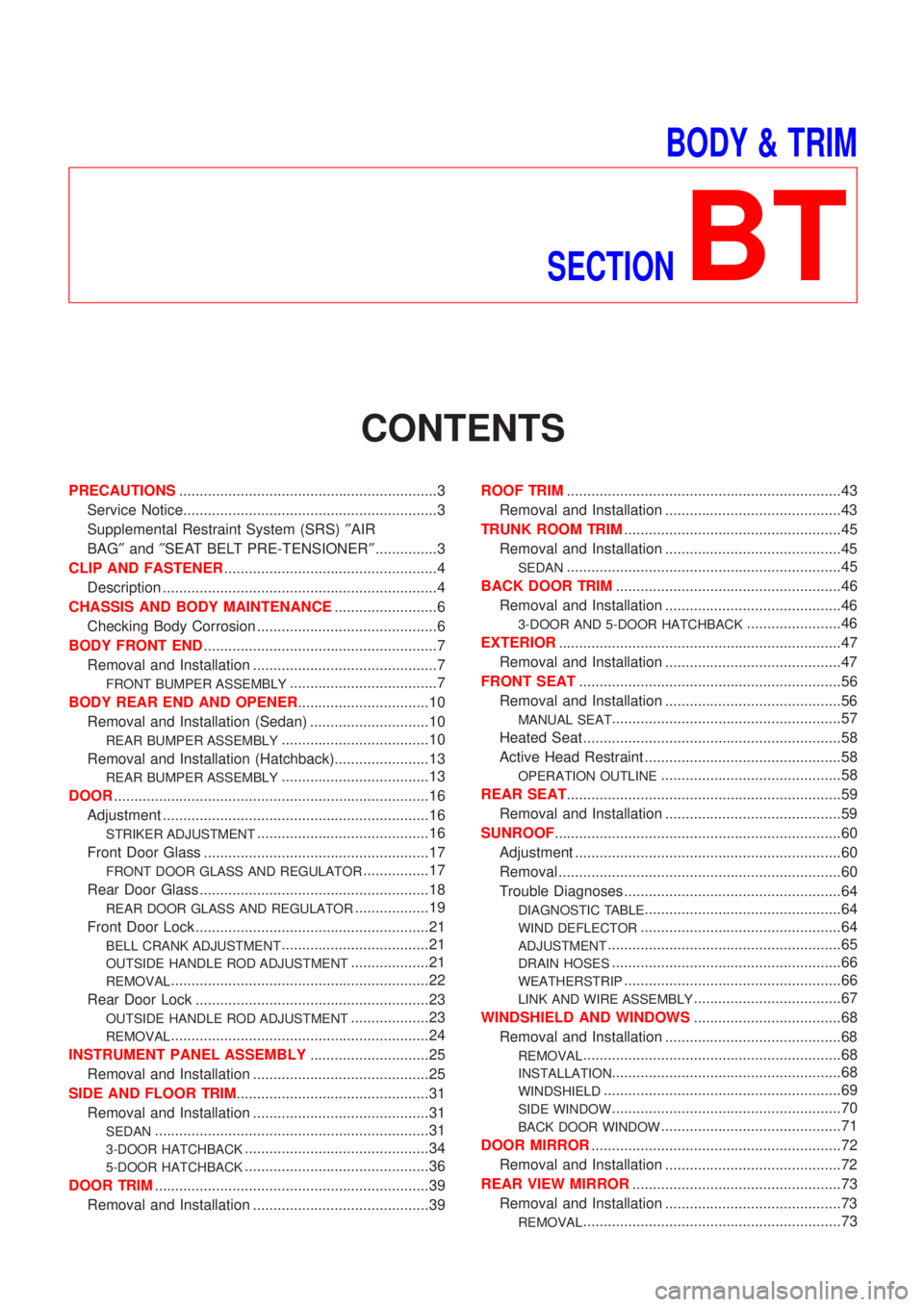
BODY & TRIM
SECTION
BT
CONTENTS
PRECAUTIONS...............................................................3
Service Notice..............................................................3
Supplemental Restraint System (SRS)²AIR
BAG²and²SEAT BELT PRE-TENSIONER²...............3
CLIP AND FASTENER....................................................4
Description ...................................................................4
CHASSIS AND BODY MAINTENANCE.........................6
Checking Body Corrosion ............................................6
BODY FRONT END.........................................................7
Removal and Installation .............................................7
FRONT BUMPER ASSEMBLY....................................7
BODY REAR END AND OPENER................................10
Removal and Installation (Sedan) .............................10
REAR BUMPER ASSEMBLY....................................10
Removal and Installation (Hatchback).......................13
REAR BUMPER ASSEMBLY....................................13
DOOR.............................................................................16
Adjustment .................................................................16
STRIKER ADJUSTMENT..........................................16
Front Door Glass .......................................................17
FRONT DOOR GLASS AND REGULATOR................17
Rear Door Glass ........................................................18
REAR DOOR GLASS AND REGULATOR..................19
Front Door Lock .........................................................21
BELL CRANK ADJUSTMENT....................................21
OUTSIDE HANDLE ROD ADJUSTMENT...................21
REMOVAL...............................................................22
Rear Door Lock .........................................................23
OUTSIDE HANDLE ROD ADJUSTMENT...................23
REMOVAL...............................................................24
INSTRUMENT PANEL ASSEMBLY.............................25
Removal and Installation ...........................................25
SIDE AND FLOOR TRIM...............................................31
Removal and Installation ...........................................31
SEDAN...................................................................31
3-DOOR HATCHBACK.............................................34
5-DOOR HATCHBACK.............................................36
DOOR TRIM...................................................................39
Removal and Installation ...........................................39ROOF TRIM...................................................................43
Removal and Installation ...........................................43
TRUNK ROOM TRIM.....................................................45
Removal and Installation ...........................................45
SEDAN...................................................................45
BACK DOOR TRIM.......................................................46
Removal and Installation ...........................................46
3-DOOR AND 5-DOOR HATCHBACK.......................46
EXTERIOR.....................................................................47
Removal and Installation ...........................................47
FRONT SEAT................................................................56
Removal and Installation ...........................................56
MANUAL SEAT........................................................57
Heated Seat ...............................................................58
Active Head Restraint ................................................58
OPERATION OUTLINE............................................58
REAR SEAT...................................................................59
Removal and Installation ...........................................59
SUNROOF......................................................................60
Adjustment .................................................................60
Removal .....................................................................60
Trouble Diagnoses.....................................................64
DIAGNOSTIC TABLE................................................64
WIND DEFLECTOR.................................................64
ADJUSTMENT.........................................................65
DRAIN HOSES........................................................66
WEATHERSTRIP.....................................................66
LINK AND WIRE ASSEMBLY....................................67
WINDSHIELD AND WINDOWS....................................68
Removal and Installation ...........................................68
REMOVAL...............................................................68
INSTALLATION........................................................68
WINDSHIELD..........................................................69
SIDE WINDOW........................................................70
BACK DOOR WINDOW............................................71
DOOR MIRROR.............................................................72
Removal and Installation ...........................................72
REAR VIEW MIRROR...................................................73
Removal and Installation ...........................................73
REMOVAL...............................................................73
Page 1896 of 2493
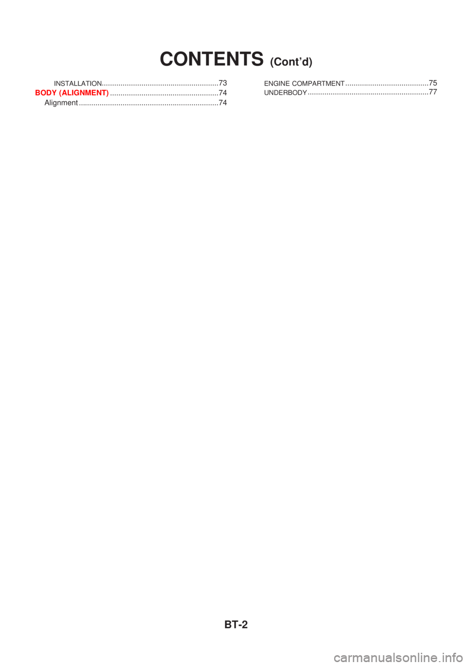
INSTALLATION........................................................73
BODY (ALIGNMENT)....................................................74
Alignment ...................................................................74ENGINE COMPARTMENT........................................75
UNDERBODY..........................................................77
CONTENTS(Cont'd)
BT-2
Page 1897 of 2493
Service NoticeNJBT0001+When removing or installing various parts, place a cloth or padding onto the vehicle body to prevent
scratches.
+Handle trim, molding, instruments, grille, etc. carefully during removing or installing. Be careful not to oil
or damage them.
+Apply sealing compound where necessary when installing parts.
+When applying sealing compound, be careful that the sealing compound does not protrude from parts.
+When replacing any metal parts (for example body outer panel, members, etc.), be sure to take rust pre-
vention measures.
Supplemental Restraint System (SRS) ªAIR
BAGº and ªSEAT BELT PRE-TENSIONERº
NJBT0002The Supplemental Restraint System such as ªAIR BAGº and ªSEAT BELT PRE-TENSIONERº used along with
a seat belt, helps to reduce the risk or severity of injury to the driver and front passenger for certain types of
collision. The SRS system composition which is available to NISSAN MODEL N16 is as follows (The compo-
sition varies according to the destination and optional equipment.):
+For a frontal collision
The Supplemental Restraint System consists of driver air bag module (located in the center of the steer-
ing wheel), front passenger air bag module (located on the instrument panel on passenger side), front seat
belt pre-tensioners, a diagnosis sensor unit, warning lamp, wiring harness and spiral cable.
+For a side collision
The Supplemental Restraint System consists of front side air bag module (located in the outer side of front
seat), side air bag (satellite) sensor, diagnosis sensor unit (one of components of air bags for a frontal
collision), wiring harness, warning lamp (one of components of air bags for a frontal collision).
Information necessary to service the system safely is included in theRS sectionof this Service Manual.
WARNING:
+To avoid rendering the SRS inoperative, which could increase the risk of personal injury or death
in the event of a collision which would result in air bag inflation, all maintenance should be per-
formed by an authorized NISSAN dealer.
+Improper maintenance, including incorrect removal and installation of the SRS, can lead to per-
sonal injury caused by unintentional activation of the system. For removal of Spiral Cable and Air
Bag Module, see the RS section.
+Do not use electrical test equipment on any circuit related to the SRS unless instructed to in this
Service Manual. SRS wiring harnesses can be identified by yellow harness connector.
PRECAUTIONS
Service Notice
BT-3
Page 1898 of 2493
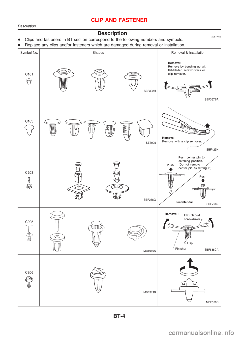
DescriptionNJBT0003+Clips and fasteners in BT section correspond to the following numbers and symbols.
+Replace any clips and/or fasteners which are damaged during removal or installation.
Symbol No. Shapes Removal & Installation
C101
SBF302H
SBF367BA
C103
SBT095
SBF423H
C203
SBF258G
SBF708E
C205
MBT080ASBF638CA
C206
MBF519B
MBF520B
CLIP AND FASTENER
Description
BT-4
Page 1899 of 2493
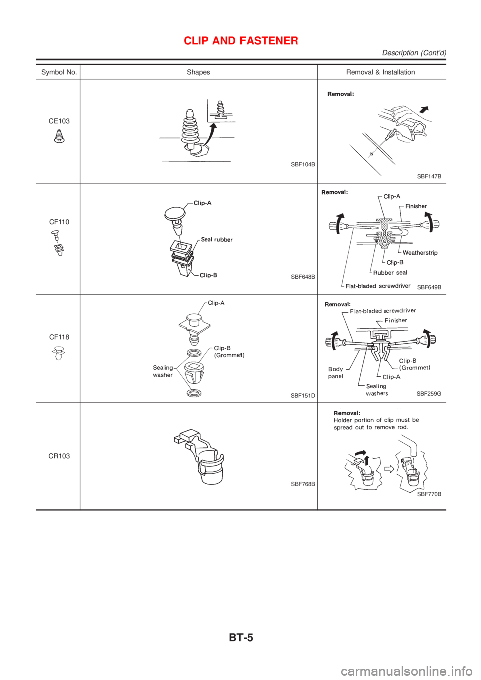
Symbol No. Shapes Removal & Installation
CE103
SBF104B
SBF147B
CF110
SBF648B
SBF649B
CF118
SBF151DSBF259G
CR103
SBF768B
SBF770B
CLIP AND FASTENER
Description (Cont'd)
BT-5
Page 1900 of 2493
Checking Body CorrosionNJBT0033Visually check the body sheet metal panel for corrosion, paint damage (scratches, chipping, rubbing, etc.) or
damage to the anti-corrosion materials. In particular, check the following locations.
Hemmed portion
Hood front end, door lower end, trunk lid rear end, etc.
Panel joint
Side sill of rear fender and center pillar, rear wheel housing of rear fender, around strut tower in engine
compartment, etc.
Panel edge
Trunk lid opening, sunroof opening, fender wheelarch flange, fuel filler lid flange, around holes in panel, etc.
Parts contact
Waist molding, windshield molding, bumper, etc.
Protectors
Damage or condition of mudguard, fender protector, chipping protector, etc.
Anti-corrosion materials
Damage or separation of anti-corrosion materials under the body.
Drain holes
Condition of drain holes at door and side sill.
When repairing corroded areas, refer to the Corrosion Repair Manual.
CHASSIS AND BODY MAINTENANCE
Checking Body Corrosion
BT-6