battery NISSAN ALMERA N16 2001 Electronic Service Manual
[x] Cancel search | Manufacturer: NISSAN, Model Year: 2001, Model line: ALMERA N16, Model: NISSAN ALMERA N16 2001Pages: 2493, PDF Size: 66.97 MB
Page 430 of 2493
![NISSAN ALMERA N16 2001 Electronic Service Manual TERMI-
NAL
NO.WIRE
COLORITEM CONDITION DATA (DC Voltage)
3 W/RHeated oxygen sensor 2
heater (rear)[Engine is running]
+Engine speed is below 3,600 rpm
+After driving for 2 minutes at a speed of 70
km/](/img/5/57351/w960_57351-429.png "NISSAN ALMERA N16 2001 Electronic Service Manual TERMI-
NAL
NO.WIRE
COLORITEM CONDITION DATA (DC Voltage)
3 W/RHeated oxygen sensor 2
heater (rear)[Engine is running]
+Engine speed is below 3,600 rpm
+After driving for 2 minutes at a speed of 70
km/")
TERMI-
NAL
NO.WIRE
COLORITEM CONDITION DATA (DC Voltage)
3 W/RHeated oxygen sensor 2
heater (rear)[Engine is running]
+Engine speed is below 3,600 rpm
+After driving for 2 minutes at a speed of 70
km/h (43 MPH) or moreApproximately 0.7V
[Ignition switch ªONº]
+Engine stopped
+Engine speed is above 3,600 rpmBATTERY VOLTAGE
(11 - 14V)
4 R/BHeated oxygen sensor 1
heater (front)[Engine is running]
+Engine speed is below 3,200 rpmApproximately 0V
[Engine is running]
+Engine speed is above 3,200 rpmBATTERY VOLTAGE
(11 - 14V)
6
7
15
16BR
L/G
P
ORIACV-AAC valve[Engine is running]
+Warm-up condition
+Idle speed0.1 - 14V
8*
9*
17*
18*SB
W/B
R/Y
BR/REGR volume control
valve[Engine is running]
+Warm-up condition
+Rev engine from 2,000 to 4,000 rpm0 - 14V
10 Y/B A/T signal No. 3[Engine is running]
+Idle speedApproximately 0V
13 LG/R Cooling fan relay[Engine is running]
+Cooling fan is not operatingBATTERY VOLTAGE
(11 - 14V)
[Engine is running]
+Cooling fan is operatingApproximately 0V
14 GY/LEVAP canister purge
volume control valve
(ON/OFF duty)[Engine is running]
+Warm-up condition
+Accelerator pedal depressed5 - 12V
SEF975W
19 BR/W A/T signal No. 5[Engine is running]
+Idle speedApproximately 8V
21 B/P Fuel pump relay[Ignition switch ªONº]
+For 1 second after turning ignition switch
ªONº
[Engine is running]0-1V
[Ignition switch ªONº]
+More than 1 second after turning ignition
switch ªONºBATTERY VOLTAGE
(11 - 14V)
22 OR/L Malfunction indicator[Ignition switch ªONº]0-1V
[Engine is running]
+Idle speedBATTERY VOLTAGE
(11 - 14V)
23 L Air conditioner relay[Engine is running]
+Both A/C switch and blower switch are ªONºApproximately 0V
[Engine is running]
+A/C switch is ªOFFºBATTERY VOLTAGE
(11 - 14V)
TROUBLE DIAGNOSIS Ð GENERAL DESCRIPTIONQG
ECM Terminals and Reference Value (Cont'd)
EC-134
Page 431 of 2493
![NISSAN ALMERA N16 2001 Electronic Service Manual TERMI-
NAL
NO.WIRE
COLORITEM CONDITION DATA (DC Voltage)
31 W/G ECM relay (Self shut-off)[Ignition switch ªOFFº]
+For 9 seconds after turning ignition switch
ªOFFº0-1V
[Ignition switch ªOFFº]
+9](/img/5/57351/w960_57351-430.png "NISSAN ALMERA N16 2001 Electronic Service Manual TERMI-
NAL
NO.WIRE
COLORITEM CONDITION DATA (DC Voltage)
31 W/G ECM relay (Self shut-off)[Ignition switch ªOFFº]
+For 9 seconds after turning ignition switch
ªOFFº0-1V
[Ignition switch ªOFFº]
+9")
TERMI-
NAL
NO.WIRE
COLORITEM CONDITION DATA (DC Voltage)
31 W/G ECM relay (Self shut-off)[Ignition switch ªOFFº]
+For 9 seconds after turning ignition switch
ªOFFº0-1V
[Ignition switch ªOFFº]
+9 seconds passed after turning ignition switch
ªOFFºBATTERY VOLTAGE
(11 - 14V)
32 L/OR Tachometer[Engine is running]
+Warm-up condition
+Idle speed7-8V
SEF928X
[Engine is running]
+Engine speed is 2,000 rpm7-8V
SEF929X
35
36
37
38L/W
PU
L/R
GY/RIgnition signal (No. 1)
Ignition signal (No. 2)
Ignition signal (No. 3)
Ignition signal (No. 4)[Engine is running]
+Warm-up condition
+Idle speed0 - 0.2VSEF971W
[Engine is running]
+Engine speed is 2,000 rpm0.2 - 0.4V
SEF972W
40* Y/PUThrottle position switch
(Closed position)[Engine is running]
+Accelerator pedal releasedBATTERY VOLTAGE
(11 - 14V)
[Engine is running]
+Accelerator pedal depressedApproximately 0V
41 B/Y Start signal[Ignition switch ªONº]Approximately 0V
[Ignition switch ªSTARTº]9 - 12V
TROUBLE DIAGNOSIS Ð GENERAL DESCRIPTIONQG
ECM Terminals and Reference Value (Cont'd)
EC-135
Page 432 of 2493
![NISSAN ALMERA N16 2001 Electronic Service Manual TERMI-
NAL
NO.WIRE
COLORITEM CONDITION DATA (DC Voltage)
42 G/OR PNP switch[Ignition switch ªONº]
+Gear position is ªNeutral positionº (M/T mod-
els)
+Gear position is ªPº or ªNº (A/T models)A](/img/5/57351/w960_57351-431.png "NISSAN ALMERA N16 2001 Electronic Service Manual TERMI-
NAL
NO.WIRE
COLORITEM CONDITION DATA (DC Voltage)
42 G/OR PNP switch[Ignition switch ªONº]
+Gear position is ªNeutral positionº (M/T mod-
els)
+Gear position is ªPº or ªNº (A/T models)A")
TERMI-
NAL
NO.WIRE
COLORITEM CONDITION DATA (DC Voltage)
42 G/OR PNP switch[Ignition switch ªONº]
+Gear position is ªNeutral positionº (M/T mod-
els)
+Gear position is ªPº or ªNº (A/T models)Approximately 0V
[Ignition switch ªONº]
+Except the above gear positionA/T models
BATTERY VOLTAGE
(11 - 14V)
M/T models
Approximately 5V
43 B/R Ignition switch[Ignition switch ªOFFº]0V
[Ignition switch ªONº]BATTERY VOLTAGE
(11 - 14V)
44 L/R Air conditioner switch[Engine is running]
+Both air conditioner switch and blower switch
are ªONº (Compressor operates)Approximately 0V
[Engine is running]
+Air conditioner switch is ªOFFºApproximately 5V
46 PU/WPower steering oil pres-
sure switch[Engine is running]
+Steering wheel is fully turnedApproximately 0V
[Engine is running]
+Steering wheel is not turnedApproximately 5V
48 B ECM ground[Engine is running]
+Idle speedEngine ground
50 L/BElectrical load signal
(Headlamp and
Rear defogger)[Engine is running]
+Headlamp switch or rear defogger switch is
ªONºBATTERY VOLTAGE
(11 - 14V)
[Engine is running]
+Headlamp switch and rear defogger switch
are ªOFFºApproximately 0V
51 LG/B Blower fan SW[Ignition switch ªONº]
+Blower fan switch is ªONºApproximately 0V
[Ignition switch ªONº]
+Blower fan switch is ªOFFºApproximately 5V
54 Y/R A/T signal No. 1[Engine is running]
+Idle speedApproximately 0V
55 Y/G A/T signal No. 2[Engine is running]
+Idle speedApproximately 0V
56 G/Y A/T signal No. 4[Engine is running]
+Idle speedApproximately 0V
57 B ECM ground[Engine is running]
+Idle speedEngine ground
58 B Sensors' ground[Engine is running]
+Warm-up condition
+Idle speedApproximately 0V
TROUBLE DIAGNOSIS Ð GENERAL DESCRIPTIONQG
ECM Terminals and Reference Value (Cont'd)
EC-136
Page 433 of 2493
![NISSAN ALMERA N16 2001 Electronic Service Manual TERMI-
NAL
NO.WIRE
COLORITEM CONDITION DATA (DC Voltage)
61 G Mass air flow sensor[Engine is running]
+Warm-up condition
+Idle speed1.0 - 1.7V
[Engine is running]
+Warm-up condition
+Engine speed is 2](/img/5/57351/w960_57351-432.png "NISSAN ALMERA N16 2001 Electronic Service Manual TERMI-
NAL
NO.WIRE
COLORITEM CONDITION DATA (DC Voltage)
61 G Mass air flow sensor[Engine is running]
+Warm-up condition
+Idle speed1.0 - 1.7V
[Engine is running]
+Warm-up condition
+Engine speed is 2")
TERMI-
NAL
NO.WIRE
COLORITEM CONDITION DATA (DC Voltage)
61 G Mass air flow sensor[Engine is running]
+Warm-up condition
+Idle speed1.0 - 1.7V
[Engine is running]
+Warm-up condition
+Engine speed is 2,500 rpm1.5 - 2.1V
62 WHeated oxygen sensor 1
(front)[Engine is running]
+Warm-up condition
+Engine speed is 2,000 rpm0 - Approximately 0.7V
SEF008W
63 LHeated oxygen sensor 2
(rear)[Engine is running]
+After warming up to normal operating tem-
perature and engine speed is 3,000 rpm0 - Approximately 1.0V
64 Y/BIntake air temperature
sensor[Engine is running]Approximately 0 - 4.8V
Output voltage varies with
intake air temperature
66
75R
RCamshaft position sen-
sor (PHASE)[Engine is running]
+Warm-up condition
+Idle speed2.0 - 3.0V
SEF977W
[Engine is running]
+Engine speed is 2,000 rpm2.0 - 3.0V
SEF978W
67 W/LPower supply for ECM
(Back-up)[Ignition switch ªOFFº]BATTERY VOLTAGE
(11 - 14V)
70 BR/WEngine coolant tempera-
ture sensor[Engine is running]Approximately 0 - 4.8V
Output voltage varies with
engine coolant temperature
71 GYThrottle position sensor
signal output[Engine is running]
+Warm-up condition
+Accelerator pedal fully releasedApproximately 0.4V
[Ignition switch ªONº]
+Accelerator pedal fully depressedApproximately 4V
TROUBLE DIAGNOSIS Ð GENERAL DESCRIPTIONQG
ECM Terminals and Reference Value (Cont'd)
EC-137
Page 435 of 2493
![NISSAN ALMERA N16 2001 Electronic Service Manual TERMI-
NAL
NO.WIRE
COLORITEM CONDITION DATA (DC Voltage)
93 G/R Data link connector[Engine is running]
+Idle speed (CONSULT-II or GST is discon-
nected)Approximately 0V
101
103
105
107R/B
YB
GB
L/BInj](/img/5/57351/w960_57351-434.png "NISSAN ALMERA N16 2001 Electronic Service Manual TERMI-
NAL
NO.WIRE
COLORITEM CONDITION DATA (DC Voltage)
93 G/R Data link connector[Engine is running]
+Idle speed (CONSULT-II or GST is discon-
nected)Approximately 0V
101
103
105
107R/B
YB
GB
L/BInj")
TERMI-
NAL
NO.WIRE
COLORITEM CONDITION DATA (DC Voltage)
93 G/R Data link connector[Engine is running]
+Idle speed (CONSULT-II or GST is discon-
nected)Approximately 0V
101
103
105
107R/B
YB
GB
L/BInjector No. 1
Injector No. 2
Injector No. 3
Injector No. 4[Engine is running]
+Warm-up condition
+Idle speedBATTERY VOLTAGE
(11 - 14V)
SEF011W
[Engine is running]
+Warm-up condition
+Engine speed is 2,000 rpmBATTERY VOLTAGE
(11 - 14V)
SEF012W
106
108B/Y ECM ground[Engine is running]
+Idle speedEngine ground
11 0
11 2W
WPower supply for ECM[Ignition switch ªONº]BATTERY VOLTAGE
(11 - 14V)
111 R Sensors' power supply[Ignition switch ªONº]Approximately 5V
114 GY/R Adjust switch[Engine is running]
+Idle speed0V
115 LG Data link connector[Engine is running]
+Idle speed (CONSULT-II or GST is discon-
nected)0 - 10V
* If so equipped
TROUBLE DIAGNOSIS Ð GENERAL DESCRIPTIONQG
ECM Terminals and Reference Value (Cont'd)
EC-139
Page 442 of 2493
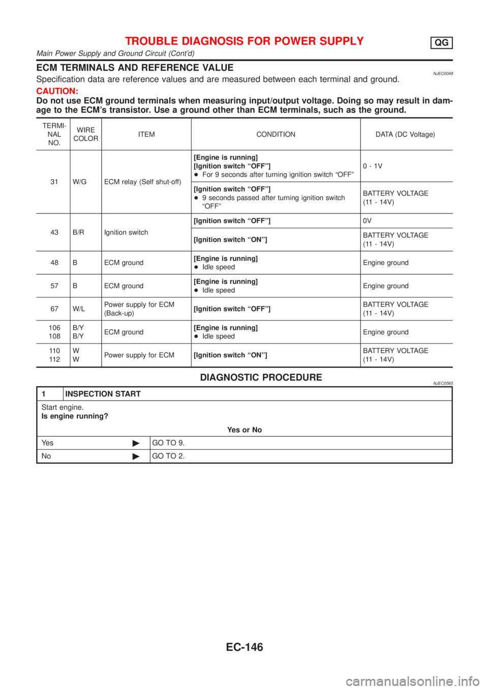
ECM TERMINALS AND REFERENCE VALUENJEC0048Specification data are reference values and are measured between each terminal and ground.
CAUTION:
Do not use ECM ground terminals when measuring input/output voltage. Doing so may result in dam-
age to the ECM's transistor. Use a ground other than ECM terminals, such as the ground.
TERMI-
NAL
NO.WIRE
COLORITEM CONDITION DATA (DC Voltage)
31 W/G ECM relay (Self shut-off)[Engine is running]
[Ignition switch ªOFFº]
+For 9 seconds after turning ignition switch ªOFFº0-1V
[Ignition switch ªOFFº]
+9 seconds passed after turning ignition switch
ªOFFºBATTERY VOLTAGE
(11 - 14V)
43 B/R Ignition switch[Ignition switch ªOFFº]0V
[Ignition switch ªONº]BATTERY VOLTAGE
(11 - 14V)
48 B ECM ground[Engine is running]
+Idle speedEngine ground
57 B ECM ground[Engine is running]
+Idle speedEngine ground
67 W/LPower supply for ECM
(Back-up)[Ignition switch ªOFFº]BATTERY VOLTAGE
(11 - 14V)
106
108B/Y
B/YECM ground[Engine is running]
+Idle speedEngine ground
11 0
11 2W
WPower supply for ECM[Ignition switch ªONº]BATTERY VOLTAGE
(11 - 14V)
DIAGNOSTIC PROCEDURENJEC0565
1 INSPECTION START
Start engine.
Is engine running?
YesorNo
Ye s©GO TO 9.
No©GO TO 2.
TROUBLE DIAGNOSIS FOR POWER SUPPLYQG
Main Power Supply and Ground Circuit (Cont'd)
EC-146
Page 444 of 2493
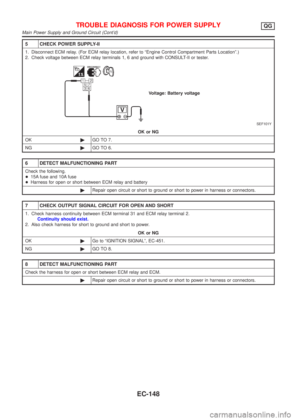
5 CHECK POWER SUPPLY-II
1. Disconnect ECM relay. (For ECM relay location, refer to ªEngine Control Compartment Parts Locationº.)
2. Check voltage between ECM relay terminals 1, 6 and ground with CONSULT-II or tester.
SEF101Y
OK or NG
OK©GO TO 7.
NG©GO TO 6.
6 DETECT MALFUNCTIONING PART
Check the following.
+15A fuse and 10A fuse
+Harness for open or short between ECM relay and battery
©Repair open circuit or short to ground or short to power in harness or connectors.
7 CHECK OUTPUT SIGNAL CIRCUIT FOR OPEN AND SHORT
1. Check harness continuity between ECM terminal 31 and ECM relay terminal 2.
Continuity should exist.
2. Also check harness for short to ground and short to power.
OK or NG
OK©Go to ªIGNITION SIGNALº, EC-451.
NG©GO TO 8.
8 DETECT MALFUNCTIONING PART
Check the harness for open or short between ECM relay and ECM.
©Repair open circuit or short to ground or short to power in harness or connectors.
TROUBLE DIAGNOSIS FOR POWER SUPPLYQG
Main Power Supply and Ground Circuit (Cont'd)
EC-148
Page 445 of 2493
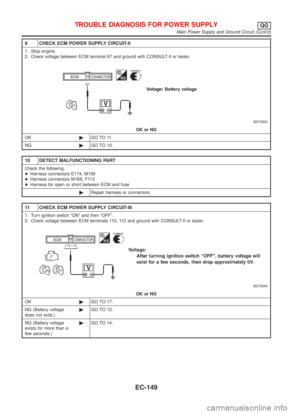
9 CHECK ECM POWER SUPPLY CIRCUIT-II
1. Stop engine.
2. Check voltage between ECM terminal 67 and ground with CONSULT-II or tester.
SEF293X
OK or NG
OK©GO TO 11.
NG©GO TO 10.
10 DETECT MALFUNCTIONING PART
Check the following.
+Harness connectors E174, M159
+Harness connectors M169, F113
+Harness for open or short between ECM and fuse
©Repair harness or connectors.
11 CHECK ECM POWER SUPPLY CIRCUIT-III
1. Turn ignition switch ªONº and then ªOFFº.
2. Check voltage between ECM terminals 110, 112 and ground with CONSULT-II or tester.
SEF294X
OK or NG
OK©GO TO 17.
NG (Battery voltage
does not exist.)©GO TO 12.
NG (Battery voltage
exists for more than a
few seconds.)©GO TO 14.
TROUBLE DIAGNOSIS FOR POWER SUPPLYQG
Main Power Supply and Ground Circuit (Cont'd)
EC-149
Page 465 of 2493
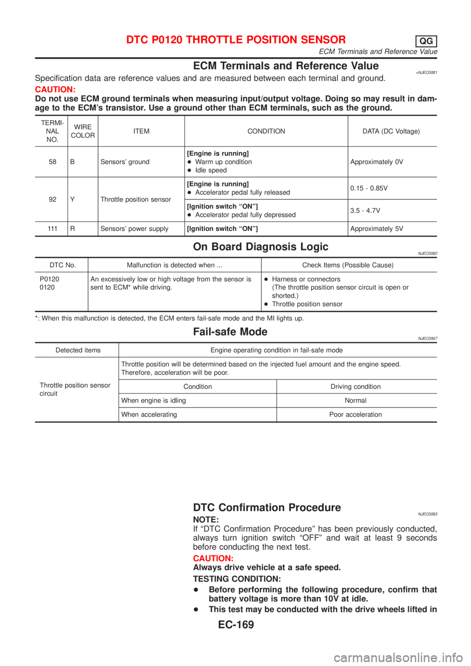
ECM Terminals and Reference Value=NJEC0081Specification data are reference values and are measured between each terminal and ground.
CAUTION:
Do not use ECM ground terminals when measuring input/output voltage. Doing so may result in dam-
age to the ECM's transistor. Use a ground other than ECM terminals, such as the ground.
TERMI-
NAL
NO.WIRE
COLORITEM CONDITION DATA (DC Voltage)
58 B Sensors' ground[Engine is running]
+Warm up condition
+Idle speedApproximately 0V
92 Y Throttle position sensor[Engine is running]
+Accelerator pedal fully released0.15 - 0.85V
[Ignition switch ªONº]
+Accelerator pedal fully depressed3.5 - 4.7V
111 R Sensors' power supply[Ignition switch ªONº]Approximately 5V
On Board Diagnosis LogicNJEC0082
DTC No. Malfunction is detected when ... Check Items (Possible Cause)
P0120
0120An excessively low or high voltage from the sensor is
sent to ECM* while driving.+Harness or connectors
(The throttle position sensor circuit is open or
shorted.)
+Throttle position sensor
*: When this malfunction is detected, the ECM enters fail-safe mode and the MI lights up.
Fail-safe ModeNJEC0567
Detected items Engine operating condition in fail-safe mode
Throttle position sensor
circuitThrottle position will be determined based on the injected fuel amount and the engine speed.
Therefore, acceleration will be poor.
Condition Driving condition
When engine is idling Normal
When accelerating Poor acceleration
DTC Confirmation ProcedureNJEC0083NOTE:
If ªDTC Confirmation Procedureº has been previously conducted,
always turn ignition switch ªOFFº and wait at least 9 seconds
before conducting the next test.
CAUTION:
Always drive vehicle at a safe speed.
TESTING CONDITION:
+Before performing the following procedure, confirm that
battery voltage is more than 10V at idle.
+This test may be conducted with the drive wheels lifted in
DTC P0120 THROTTLE POSITION SENSORQG
ECM Terminals and Reference Value
EC-169
Page 473 of 2493
SEF237U
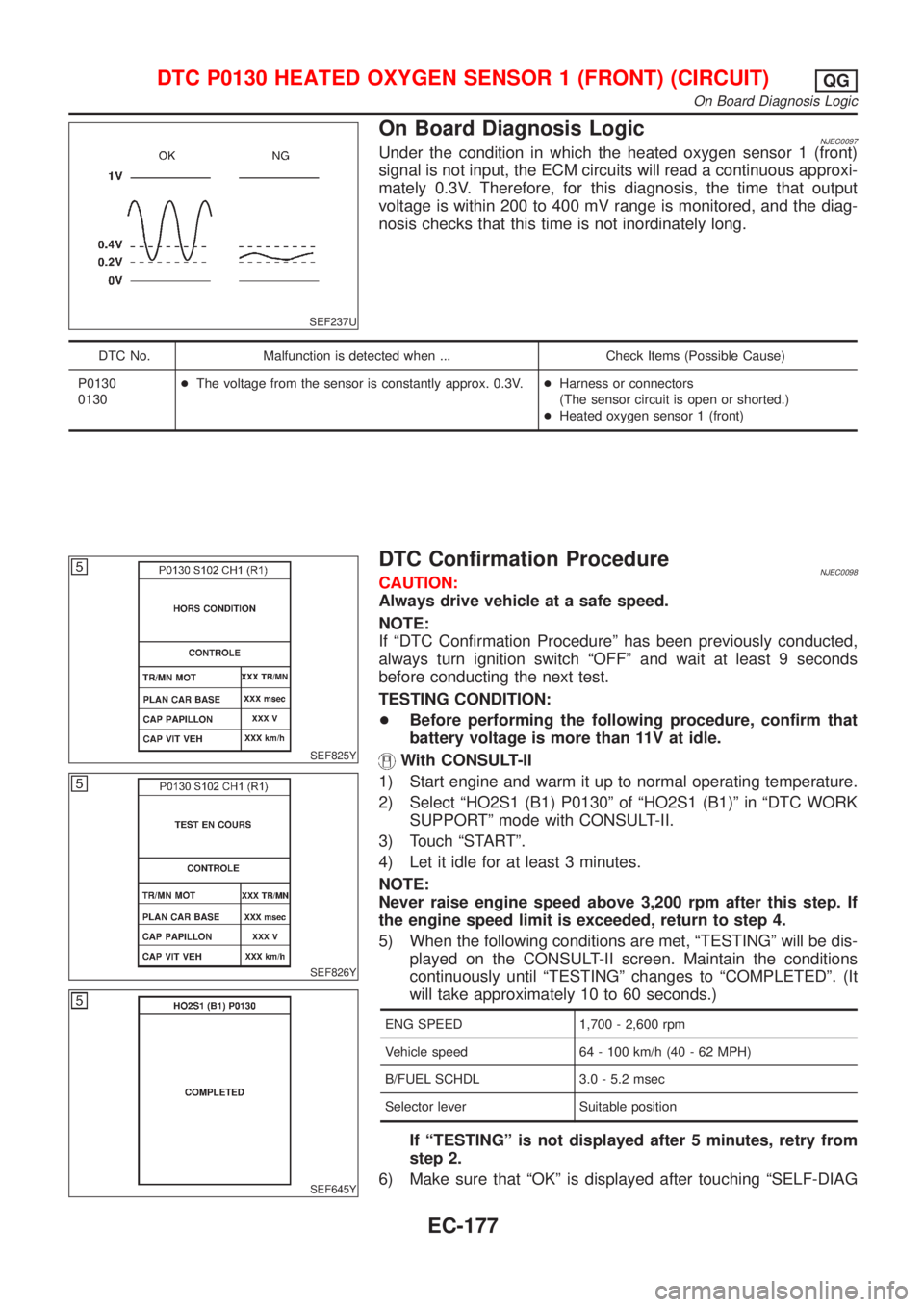
On Board Diagnosis LogicNJEC0097Under the condition in which the heated oxygen sensor 1 (front)
signal is not input, the ECM circuits will read a continuous approxi-
mately 0.3V. Therefore, for this diagnosis, the time that output
voltage is within 200 to 400 mV range is monitored, and the diag-
nosis checks that this time is not inordinately long.
DTC No. Malfunction is detected when ... Check Items (Possible Cause)
P0130
0130+The voltage from the sensor is constantly approx. 0.3V.+Harness or connectors
(The sensor circuit is open or shorted.)
+Heated oxygen sensor 1 (front)
SEF825Y
SEF826Y
SEF645Y
DTC Confirmation ProcedureNJEC0098CAUTION:
Always drive vehicle at a safe speed.
NOTE:
If ªDTC Confirmation Procedureº has been previously conducted,
always turn ignition switch ªOFFº and wait at least 9 seconds
before conducting the next test.
TESTING CONDITION:
+Before performing the following procedure, confirm that
battery voltage is more than 11V at idle.
With CONSULT-II
1) Start engine and warm it up to normal operating temperature.
2) Select ªHO2S1 (B1) P0130º of ªHO2S1 (B1)º in ªDTC WORK
SUPPORTº mode with CONSULT-II.
3) Touch ªSTARTº.
4) Let it idle for at least 3 minutes.
NOTE:
Never raise engine speed above 3,200 rpm after this step. If
the engine speed limit is exceeded, return to step 4.
5) When the following conditions are met, ªTESTINGº will be dis-
played on the CONSULT-II screen. Maintain the conditions
continuously until ªTESTINGº changes to ªCOMPLETEDº. (It
will take approximately 10 to 60 seconds.)
ENG SPEED 1,700 - 2,600 rpm
Vehicle speed 64 - 100 km/h (40 - 62 MPH)
B/FUEL SCHDL 3.0 - 5.2 msec
Selector lever Suitable position
If ªTESTINGº is not displayed after 5 minutes, retry from
step 2.
6) Make sure that ªOKº is displayed after touching ªSELF-DIAG
DTC P0130 HEATED OXYGEN SENSOR 1 (FRONT) (CIRCUIT)QG
On Board Diagnosis Logic
EC-177