battery NISSAN ALMERA N16 2001 Electronic Manual PDF
[x] Cancel search | Manufacturer: NISSAN, Model Year: 2001, Model line: ALMERA N16, Model: NISSAN ALMERA N16 2001Pages: 2493, PDF Size: 66.97 MB
Page 649 of 2493
DescriptionNJEC0349SYSTEM DESCRIPTIONNJEC0349S01
Sensor Input Signal to ECMECM func-
tionActuator
Crankshaft position sensor (POS) Engine speed
EGR vol-
ume controlEGR volume control valve Camshaft position sensor (PHASE) Engine speed and cylinder number
Mass air flow sensor Amount of intake air
Engine coolant temperature sensor Engine coolant temperature
Ignition switch Start signal
Throttle position sensor Throttle position
Vehicle speed sensor Vehicle speed
Battery Battery voltage
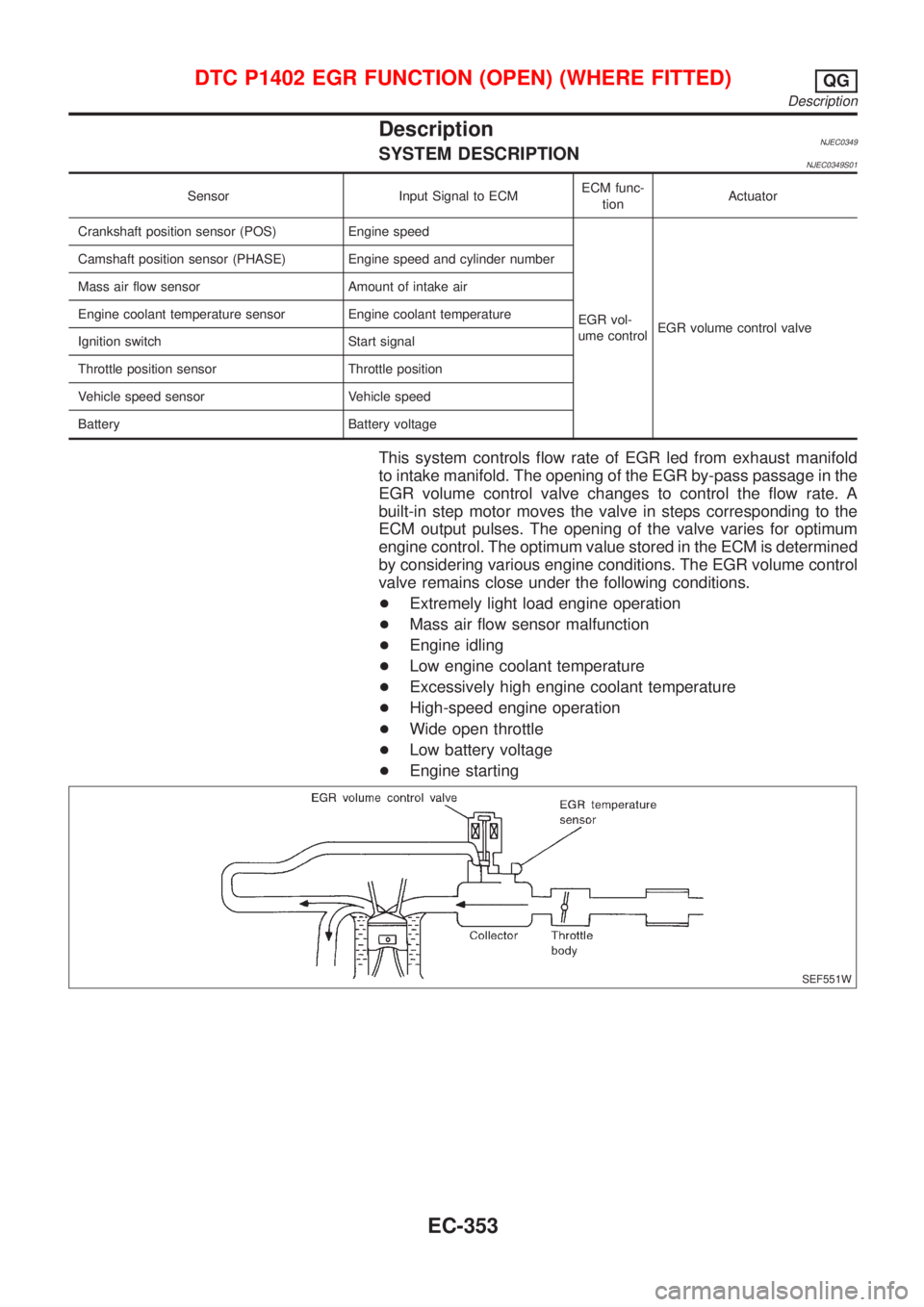
This system controls flow rate of EGR led from exhaust manifold
to intake manifold. The opening of the EGR by-pass passage in the
EGR volume control valve changes to control the flow rate. A
built-in step motor moves the valve in steps corresponding to the
ECM output pulses. The opening of the valve varies for optimum
engine control. The optimum value stored in the ECM is determined
by considering various engine conditions. The EGR volume control
valve remains close under the following conditions.
+Extremely light load engine operation
+Mass air flow sensor malfunction
+Engine idling
+Low engine coolant temperature
+Excessively high engine coolant temperature
+High-speed engine operation
+Wide open throttle
+Low battery voltage
+Engine starting
SEF551W
DTC P1402 EGR FUNCTION (OPEN) (WHERE FITTED)QG
Description
EC-353
Page 657 of 2493
System DescriptionNJEC0573The malfunction information related to A/T (Automatic Transaxle) is transferred through the line (circuit) from
TCM (Transmission Control Module) to ECM. Therefore, be sure to erase the malfunction information such as
DTC not only in TCM (Transmission Control Module) but also ECM after the A/T related repair.
ECM Terminals and Reference ValueNJEC0574Specification data are reference values and are measured between each terminal and ground.
CAUTION:
Do not use ECM ground terminals when measuring input/output voltage. Doing so may result in dam-
age to the ECM's transistor. Use a ground other than ECM terminals, such as the ground.
TERMI-
NAL
NO.WIRE
COLORITEM CONDITION DATA (DC Voltage)
91 PU A/T check signal[Ignition switch ªONº]0 - Approximately 5V
On Board Diagnosis LogicNJEC0575
DTC No. Malfunction is detected when ... Check Items (Possible Cause)
P1605
1605+An incorrect signal from TCM (Transmission Control
Module) is sent to ECM.+Harness or connectors
[The communication line circuit between ECM
and TCM (Transmission Control Module) is open
or shorted.]
+Dead (Weak) battery
+TCM (Transmission Control Module)
SEF058Y
DTC Confirmation ProcedureNJEC0576NOTE:
If ªDTC CONFIRMATION PROCEDUREº has been previously
conducted, always turn ignition switch ªOFFº and wait at least 9
seconds before conducting the next test.
With CONSULT-II
1) Turn ignition switch ªONº.
2) Select ªDATA MONITORº mode with CONSULT-II.
3) Start engine and let it idle for at least 40 seconds.
4) If 1st trip DTC is detected, go to ªDiagnostic Procedureº,
EC-363.
With GST
Follow the procedure ªWith CONSULT-IIº above.
DTC P1605 A/T DIAGNOSIS COMMUNICATION LINEQG
System Description
EC-361
Page 660 of 2493
SEF740W
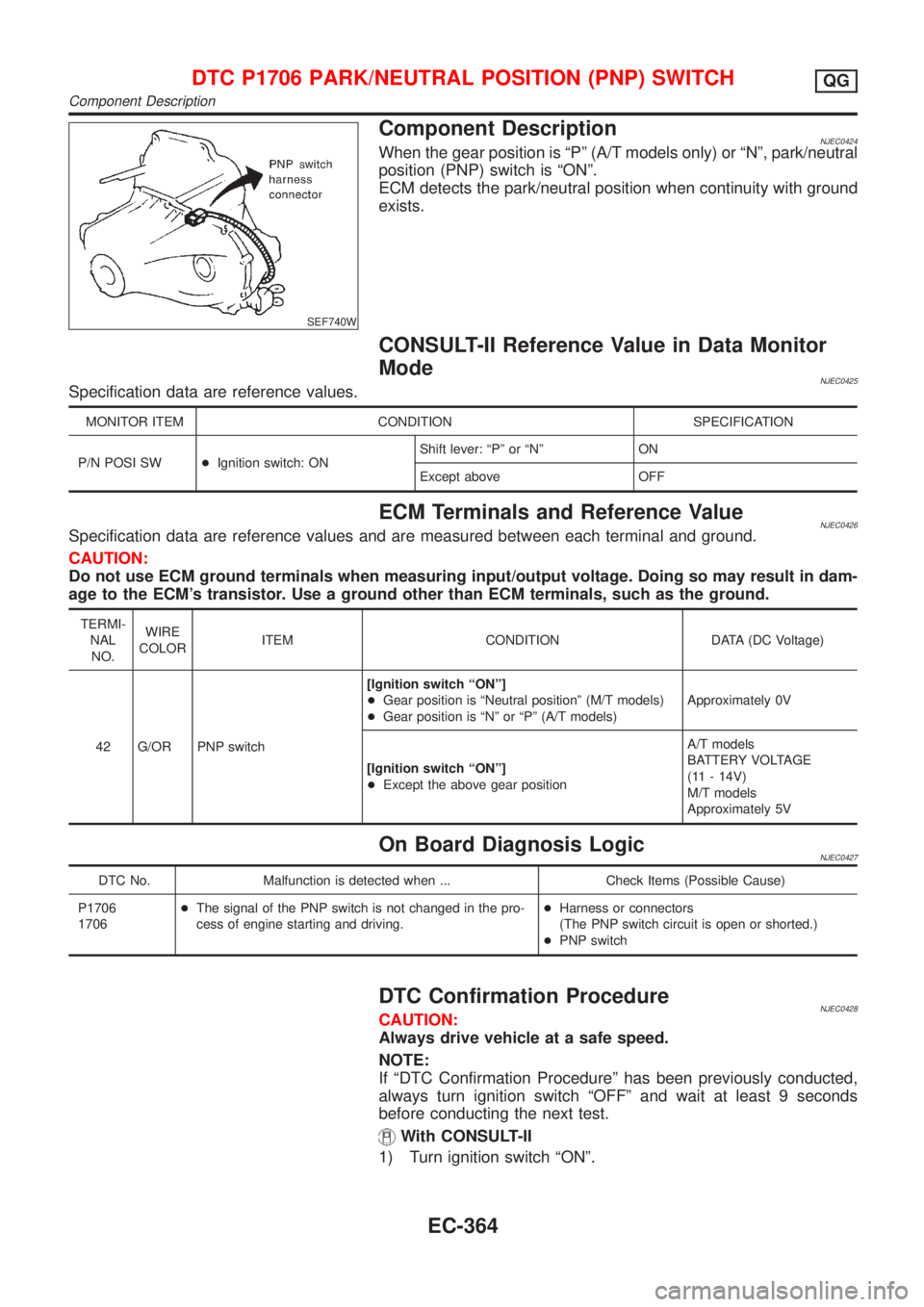
Component DescriptionNJEC0424When the gear position is ªPº (A/T models only) or ªNº, park/neutral
position (PNP) switch is ªONº.
ECM detects the park/neutral position when continuity with ground
exists.
CONSULT-II Reference Value in Data Monitor
Mode
NJEC0425Specification data are reference values.
MONITOR ITEM CONDITION SPECIFICATION
P/N POSI SW+Ignition switch: ONShift lever: ªPº or ªNº ON
Except above OFF
ECM Terminals and Reference ValueNJEC0426Specification data are reference values and are measured between each terminal and ground.
CAUTION:
Do not use ECM ground terminals when measuring input/output voltage. Doing so may result in dam-
age to the ECM's transistor. Use a ground other than ECM terminals, such as the ground.
TERMI-
NAL
NO.WIRE
COLORITEM CONDITION DATA (DC Voltage)
42 G/OR PNP switch[Ignition switch ªONº]
+Gear position is ªNeutral positionº (M/T models)
+Gear position is ªNº or ªPº (A/T models)Approximately 0V
[Ignition switch ªONº]
+Except the above gear positionA/T models
BATTERY VOLTAGE
(11 - 14V)
M/T models
Approximately 5V
On Board Diagnosis LogicNJEC0427
DTC No. Malfunction is detected when ... Check Items (Possible Cause)
P1706
1706+The signal of the PNP switch is not changed in the pro-
cess of engine starting and driving.+Harness or connectors
(The PNP switch circuit is open or shorted.)
+PNP switch
DTC Confirmation ProcedureNJEC0428CAUTION:
Always drive vehicle at a safe speed.
NOTE:
If ªDTC Confirmation Procedureº has been previously conducted,
always turn ignition switch ªOFFº and wait at least 9 seconds
before conducting the next test.
With CONSULT-II
1) Turn ignition switch ªONº.
DTC P1706 PARK/NEUTRAL POSITION (PNP) SWITCHQG
Component Description
EC-364
Page 661 of 2493
SEF213Y
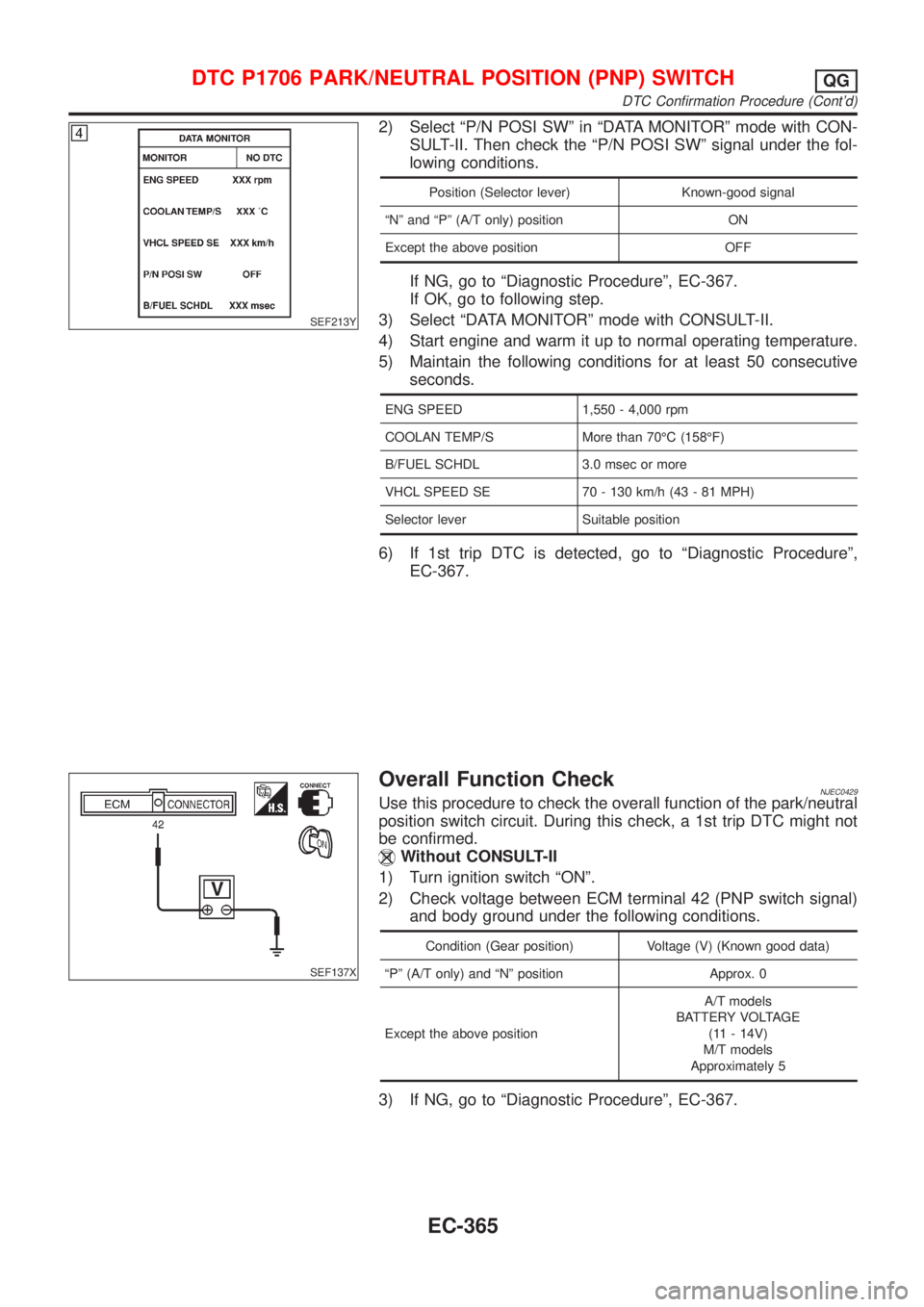
2) Select ªP/N POSI SWº in ªDATA MONITORº mode with CON-
SULT-II. Then check the ªP/N POSI SWº signal under the fol-
lowing conditions.
Position (Selector lever) Known-good signal
ªNº and ªPº (A/T only) position ON
Except the above position OFF
If NG, go to ªDiagnostic Procedureº, EC-367.
If OK, go to following step.
3) Select ªDATA MONITORº mode with CONSULT-II.
4) Start engine and warm it up to normal operating temperature.
5) Maintain the following conditions for at least 50 consecutive
seconds.
ENG SPEED 1,550 - 4,000 rpm
COOLAN TEMP/S More than 70ÉC (158ÉF)
B/FUEL SCHDL 3.0 msec or more
VHCL SPEED SE 70 - 130 km/h (43 - 81 MPH)
Selector lever Suitable position
6) If 1st trip DTC is detected, go to ªDiagnostic Procedureº,
EC-367.
SEF137X
Overall Function CheckNJEC0429Use this procedure to check the overall function of the park/neutral
position switch circuit. During this check, a 1st trip DTC might not
be confirmed.
Without CONSULT-II
1) Turn ignition switch ªONº.
2) Check voltage between ECM terminal 42 (PNP switch signal)
and body ground under the following conditions.
Condition (Gear position) Voltage (V) (Known good data)
ªPº (A/T only) and ªNº position Approx. 0
Except the above positionA/T models
BATTERY VOLTAGE
(11 - 14V)
M/T models
Approximately 5
3) If NG, go to ªDiagnostic Procedureº, EC-367.
DTC P1706 PARK/NEUTRAL POSITION (PNP) SWITCHQG
DTC Confirmation Procedure (Cont'd)
EC-365
Page 675 of 2493
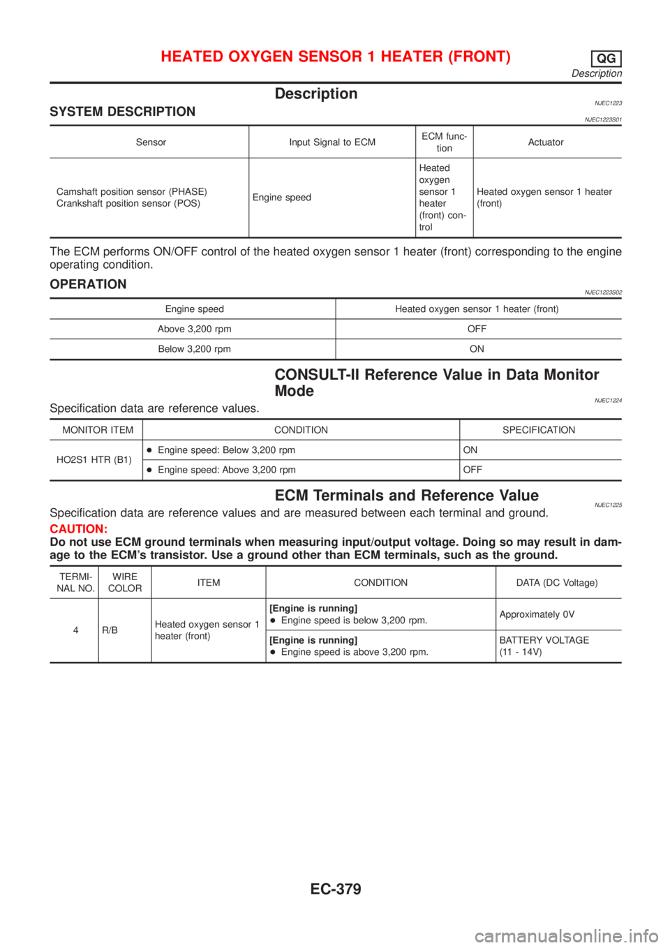
DescriptionNJEC1223SYSTEM DESCRIPTIONNJEC1223S01
Sensor Input Signal to ECMECM func-
tionActuator
Camshaft position sensor (PHASE)
Crankshaft position sensor (POS)Engine speedHeated
oxygen
sensor 1
heater
(front) con-
trolHeated oxygen sensor 1 heater
(front)
The ECM performs ON/OFF control of the heated oxygen sensor 1 heater (front) corresponding to the engine
operating condition.
OPERATIONNJEC1223S02
Engine speed Heated oxygen sensor 1 heater (front)
Above 3,200 rpm OFF
Below 3,200 rpm ON
CONSULT-II Reference Value in Data Monitor
Mode
NJEC1224Specification data are reference values.
MONITOR ITEM CONDITION SPECIFICATION
HO2S1 HTR (B1)+Engine speed: Below 3,200 rpm ON
+Engine speed: Above 3,200 rpm OFF
ECM Terminals and Reference ValueNJEC1225Specification data are reference values and are measured between each terminal and ground.
CAUTION:
Do not use ECM ground terminals when measuring input/output voltage. Doing so may result in dam-
age to the ECM's transistor. Use a ground other than ECM terminals, such as the ground.
TERMI-
NAL NO.WIRE
COLORITEM CONDITION DATA (DC Voltage)
4 R/BHeated oxygen sensor 1
heater (front)[Engine is running]
+Engine speed is below 3,200 rpm.Approximately 0V
[Engine is running]
+Engine speed is above 3,200 rpm.BATTERY VOLTAGE
(11 - 14V)
HEATED OXYGEN SENSOR 1 HEATER (FRONT)QG
Description
EC-379
Page 685 of 2493
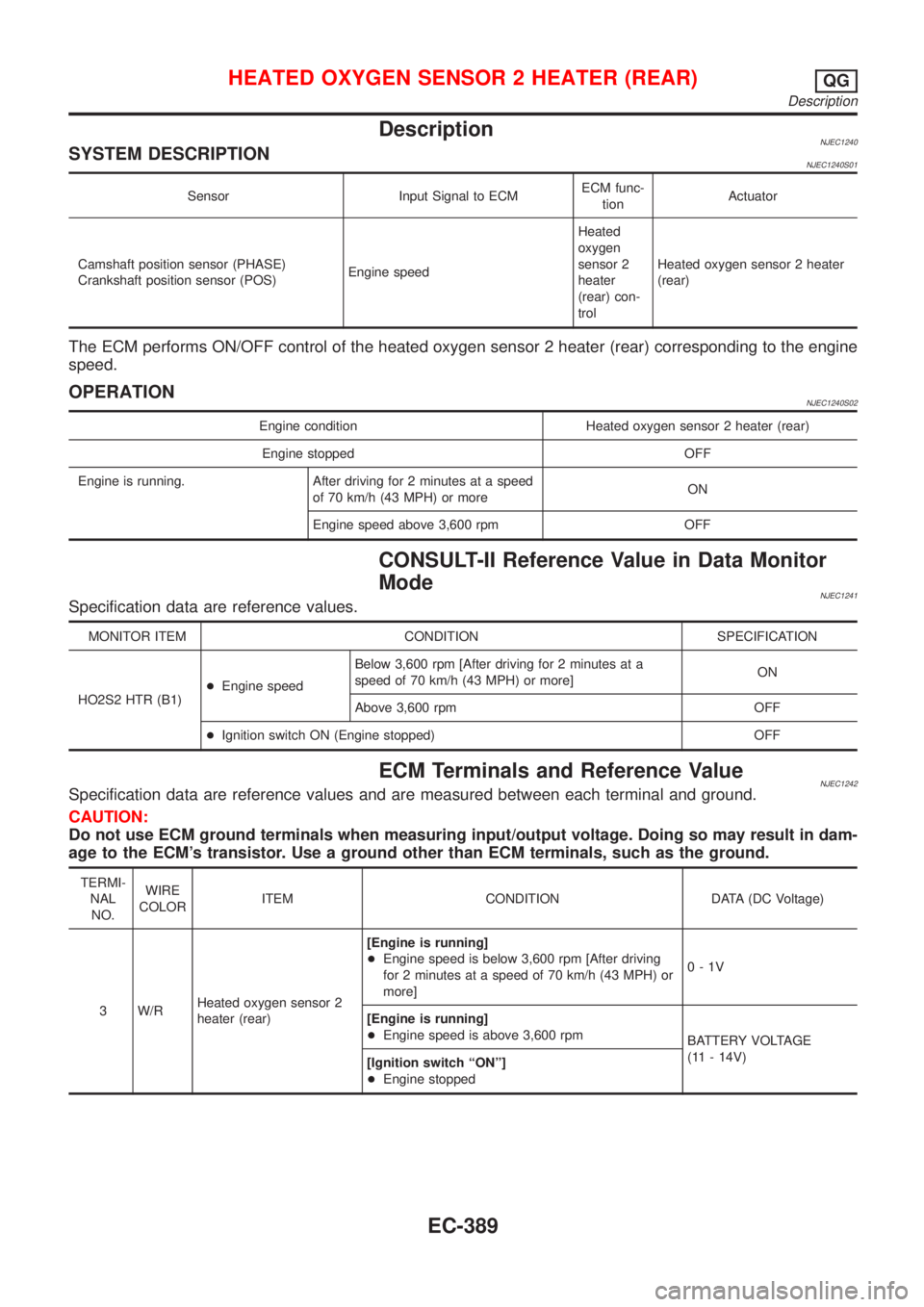
DescriptionNJEC1240SYSTEM DESCRIPTIONNJEC1240S01
Sensor Input Signal to ECMECM func-
tionActuator
Camshaft position sensor (PHASE)
Crankshaft position sensor (POS)Engine speedHeated
oxygen
sensor 2
heater
(rear) con-
trolHeated oxygen sensor 2 heater
(rear)
The ECM performs ON/OFF control of the heated oxygen sensor 2 heater (rear) corresponding to the engine
speed.
OPERATIONNJEC1240S02
Engine condition Heated oxygen sensor 2 heater (rear)
Engine stopped OFF
Engine is running. After driving for 2 minutes at a speed
of 70 km/h (43 MPH) or moreON
Engine speed above 3,600 rpm OFF
CONSULT-II Reference Value in Data Monitor
Mode
NJEC1241Specification data are reference values.
MONITOR ITEM CONDITION SPECIFICATION
HO2S2 HTR (B1)+Engine speedBelow 3,600 rpm [After driving for 2 minutes at a
speed of 70 km/h (43 MPH) or more]ON
Above 3,600 rpm OFF
+Ignition switch ON (Engine stopped) OFF
ECM Terminals and Reference ValueNJEC1242Specification data are reference values and are measured between each terminal and ground.
CAUTION:
Do not use ECM ground terminals when measuring input/output voltage. Doing so may result in dam-
age to the ECM's transistor. Use a ground other than ECM terminals, such as the ground.
TERMI-
NAL
NO.WIRE
COLORITEM CONDITION DATA (DC Voltage)
3 W/RHeated oxygen sensor 2
heater (rear)[Engine is running]
+Engine speed is below 3,600 rpm [After driving
for 2 minutes at a speed of 70 km/h (43 MPH) or
more]0-1V
[Engine is running]
+Engine speed is above 3,600 rpm
BATTERY VOLTAGE
(11 - 14V)
[Ignition switch ªONº]
+Engine stopped
HEATED OXYGEN SENSOR 2 HEATER (REAR)QG
Description
EC-389
Page 696 of 2493
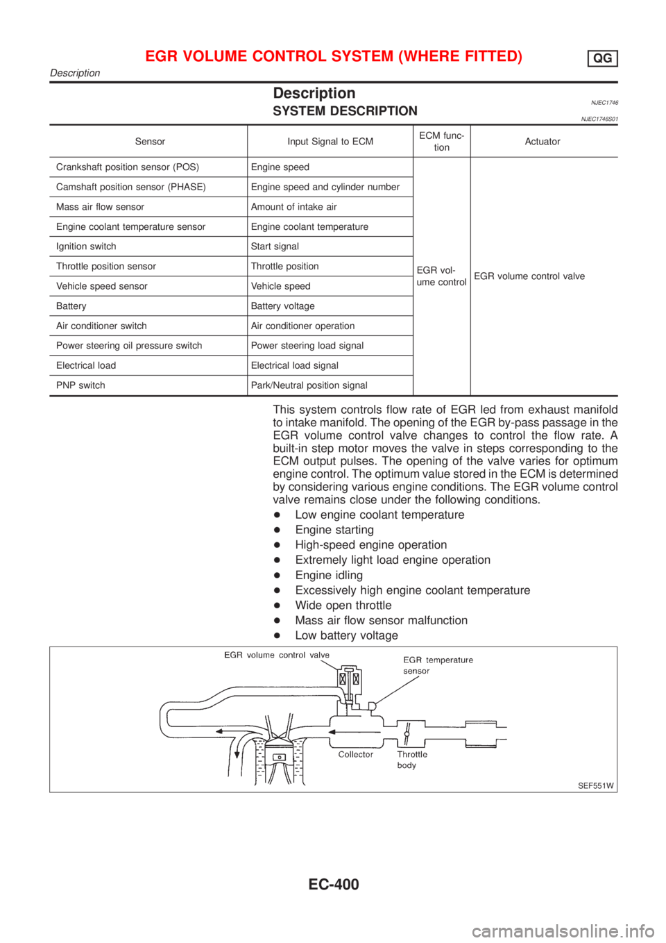
DescriptionNJEC1746SYSTEM DESCRIPTIONNJEC1746S01
Sensor Input Signal to ECMECM func-
tionActuator
Crankshaft position sensor (POS) Engine speed
EGR vol-
ume controlEGR volume control valve Camshaft position sensor (PHASE) Engine speed and cylinder number
Mass air flow sensor Amount of intake air
Engine coolant temperature sensor Engine coolant temperature
Ignition switch Start signal
Throttle position sensor Throttle position
Vehicle speed sensor Vehicle speed
Battery Battery voltage
Air conditioner switch Air conditioner operation
Power steering oil pressure switch Power steering load signal
Electrical load Electrical load signal
PNP switch Park/Neutral position signal
This system controls flow rate of EGR led from exhaust manifold
to intake manifold. The opening of the EGR by-pass passage in the
EGR volume control valve changes to control the flow rate. A
built-in step motor moves the valve in steps corresponding to the
ECM output pulses. The opening of the valve varies for optimum
engine control. The optimum value stored in the ECM is determined
by considering various engine conditions. The EGR volume control
valve remains close under the following conditions.
+Low engine coolant temperature
+Engine starting
+High-speed engine operation
+Extremely light load engine operation
+Engine idling
+Excessively high engine coolant temperature
+Wide open throttle
+Mass air flow sensor malfunction
+Low battery voltage
SEF551W
EGR VOLUME CONTROL SYSTEM (WHERE FITTED)QG
Description
EC-400
Page 707 of 2493
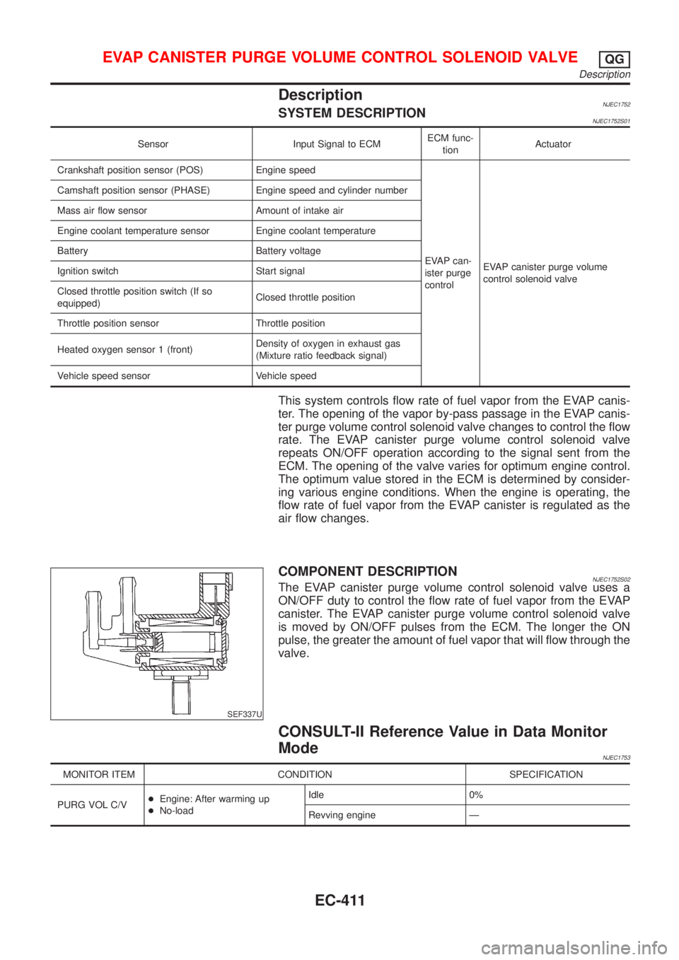
DescriptionNJEC1752SYSTEM DESCRIPTIONNJEC1752S01
Sensor Input Signal to ECMECM func-
tionActuator
Crankshaft position sensor (POS) Engine speed
EVAP can-
ister purge
controlEVAP canister purge volume
control solenoid valve Camshaft position sensor (PHASE) Engine speed and cylinder number
Mass air flow sensor Amount of intake air
Engine coolant temperature sensor Engine coolant temperature
Battery Battery voltage
Ignition switch Start signal
Closed throttle position switch (If so
equipped)Closed throttle position
Throttle position sensor Throttle position
Heated oxygen sensor 1 (front)Density of oxygen in exhaust gas
(Mixture ratio feedback signal)
Vehicle speed sensor Vehicle speed
This system controls flow rate of fuel vapor from the EVAP canis-
ter. The opening of the vapor by-pass passage in the EVAP canis-
ter purge volume control solenoid valve changes to control the flow
rate. The EVAP canister purge volume control solenoid valve
repeats ON/OFF operation according to the signal sent from the
ECM. The opening of the valve varies for optimum engine control.
The optimum value stored in the ECM is determined by consider-
ing various engine conditions. When the engine is operating, the
flow rate of fuel vapor from the EVAP canister is regulated as the
air flow changes.
SEF337U
COMPONENT DESCRIPTIONNJEC1752S02The EVAP canister purge volume control solenoid valve uses a
ON/OFF duty to control the flow rate of fuel vapor from the EVAP
canister. The EVAP canister purge volume control solenoid valve
is moved by ON/OFF pulses from the ECM. The longer the ON
pulse, the greater the amount of fuel vapor that will flow through the
valve.
CONSULT-II Reference Value in Data Monitor
Mode
NJEC1753
MONITOR ITEM CONDITION SPECIFICATION
PURG VOL C/V+Engine: After warming up
+No-loadIdle 0%
Revving engine Ð
EVAP CANISTER PURGE VOLUME CONTROL SOLENOID VALVEQG
Description
EC-411
Page 708 of 2493
ECM Terminals and Reference Value=NJEC1754Specification data are reference values and are measured between each terminal and ground.
CAUTION:
Do not use ECM ground terminals when measuring input/output voltage. Doing so may result in dam-
age to the ECM's transistor. Use a ground other than ECM terminals, such as the ground.
TER-
MINAL
NO.WIRE
COLORITEM CONDITION DATA (DC Voltage)
14 GY/LEVAP canister purge vol-
ume control solenoid valve[Engine is running]
+Warm-up condition
+Idle speedBATTERY VOLTAGE
(11 - 14V)
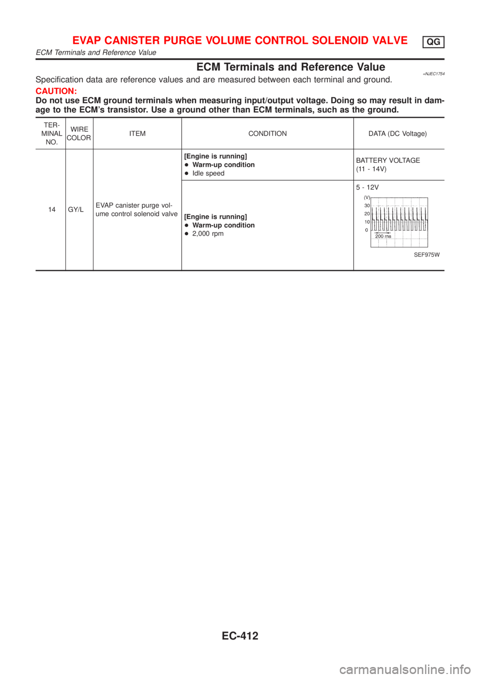
[Engine is running]
+Warm-up condition
+2,000 rpm5 - 12V
SEF975W
EVAP CANISTER PURGE VOLUME CONTROL SOLENOID VALVEQG
ECM Terminals and Reference Value
EC-412
Page 714 of 2493
DescriptionNJEC1758SYSTEM DESCRIPTIONNJEC1758S01
Sensor Input Signal to ECMECM func-
tionActuator
Crankshaft position sensor (POS) Engine speed
Idle air
controlIACV-AAC valve Camshaft position sensor (PHASE) Engine speed and cylinder number
Engine coolant temperature sensor Engine coolant temperature
Ignition switch Start signal
Throttle position sensor Throttle position
PNP switch Park/Neutral position
Air conditioner switch Air conditioner operation
Power steering oil pressure switch Power steering load signal
Battery Battery voltage
Vehicle speed sensor Vehicle speed
Cooling fan Cooling fan operation
Electrical load Electrical load signal
This system automatically controls engine idle speed to a specified
level. Idle speed is controlled through fine adjustment of the
amount of air which by-passes the throttle valve via IACV-AAC
valve. The IACV-AAC valve changes the opening of the air by-pass
passage to control the amount of auxiliary air. This valve is actu-
ated by a step motor built into the valve, which moves the valve in
the axial direction in steps corresponding to the ECM output sig-
nals. One step of IACV-AAC valve movement causes the respec-
tive opening of the air by-pass passage. (i.e. when the step
advances, the opening is enlarged.) The opening of the valve is
varied to allow for optimum control of the engine idling speed. The
crankshaft position sensor (POS) detects the actual engine speed
and sends a signal to the ECM. The ECM then controls the step
position of the IACV-AAC valve so that engine speed coincides with
the target value memorized in ECM. The target engine speed is the
lowest speed at which the engine can operate steadily. The opti-
mum value stored in the ECM is determined by taking into consid-
eration various engine conditions, such as during warm up,
deceleration, and engine load (air conditioner, power steering, cool-
ing fan operation and electrical load).
SEF937W
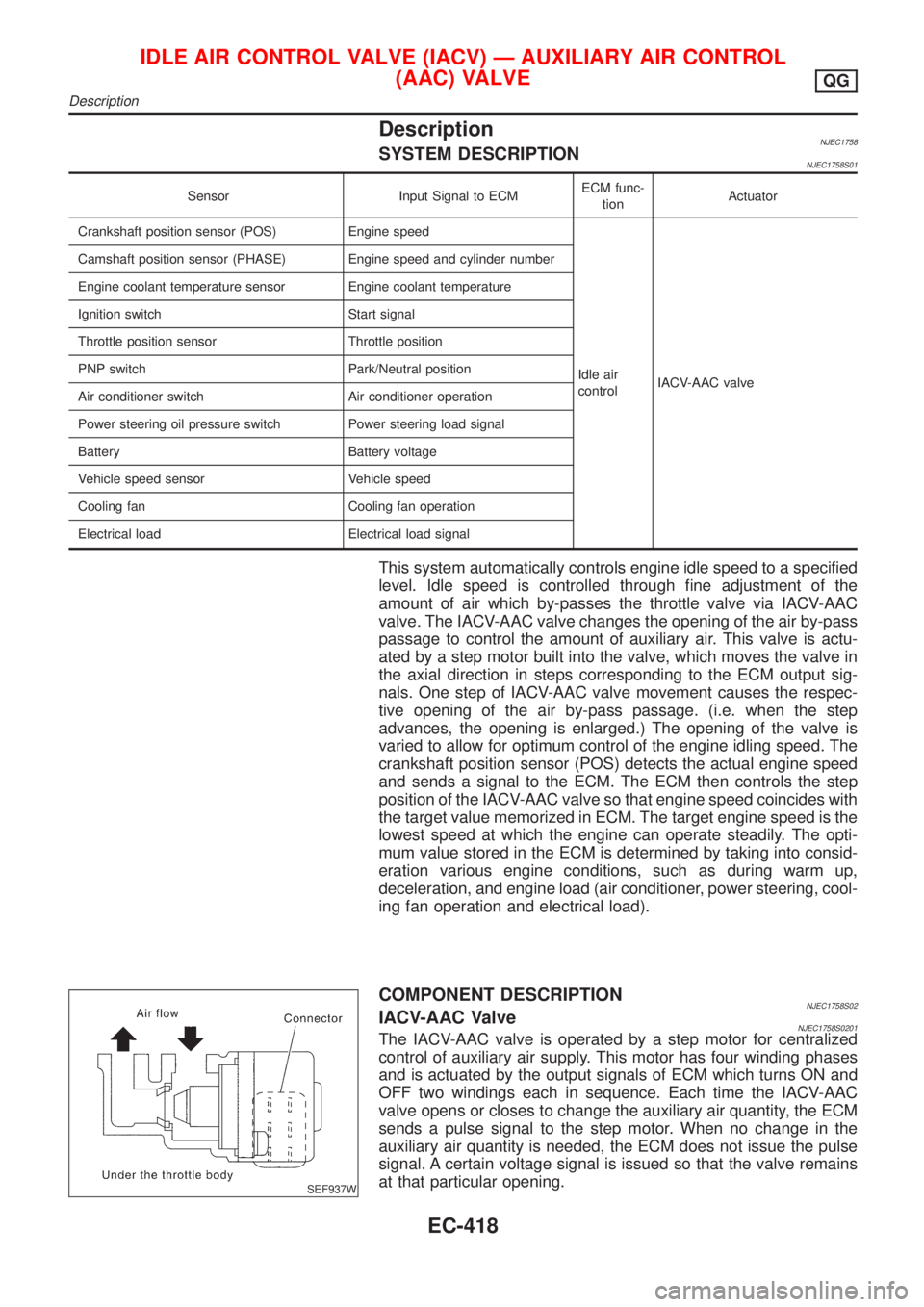
COMPONENT DESCRIPTIONNJEC1758S02IACV-AAC ValveNJEC1758S0201The IACV-AAC valve is operated by a step motor for centralized
control of auxiliary air supply. This motor has four winding phases
and is actuated by the output signals of ECM which turns ON and
OFF two windings each in sequence. Each time the IACV-AAC
valve opens or closes to change the auxiliary air quantity, the ECM
sends a pulse signal to the step motor. When no change in the
auxiliary air quantity is needed, the ECM does not issue the pulse
signal. A certain voltage signal is issued so that the valve remains
at that particular opening.
IDLE AIR CONTROL VALVE (IACV) Ð AUXILIARY AIR CONTROL
(AAC) VALVE
QG
Description
EC-418