battery NISSAN ALMERA N16 2001 Electronic Owner's Guide
[x] Cancel search | Manufacturer: NISSAN, Model Year: 2001, Model line: ALMERA N16, Model: NISSAN ALMERA N16 2001Pages: 2493, PDF Size: 66.97 MB
Page 367 of 2493
Only one set of freeze frame data (either 1st trip freeze frame data or freeze frame data) can be stored in the
ECM. 1st trip freeze frame data is stored in the ECM memory along with the 1st trip DTC. There is no prior-
ity for 1st trip freeze frame data and it is updated each time a different 1st trip DTC is detected. However, once
freeze frame data is stored in the ECM memory, 1st trip freeze frame data is no longer stored. Remember,
only one set of freeze frame data can be stored in the ECM.
If freeze frame data is stored in the ECM memory and another freeze frame data occurs later, the first (origi-
nal) freeze frame data remains unchanged in the ECM memory.
Both 1st trip freeze frame data and freeze frame data (along with the DTCs) are cleared when the ECM
memory is erased. Procedures for clearing the ECM memory are described in ªHow to Erase Emission-related
Diagnostic Informationº, EC-71.
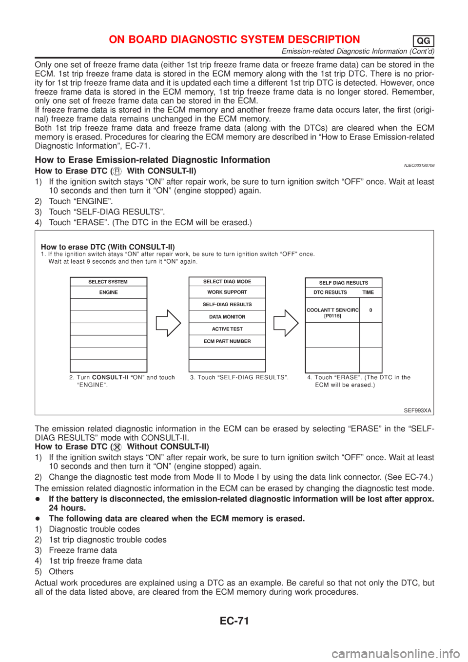
How to Erase Emission-related Diagnostic InformationNJEC0031S0706How to Erase DTC (With CONSULT-II)
1) If the ignition switch stays ªONº after repair work, be sure to turn ignition switch ªOFFº once. Wait at least
10 seconds and then turn it ªONº (engine stopped) again.
2) Touch ªENGINEº.
3) Touch ªSELF-DIAG RESULTSº.
4) Touch ªERASEº. (The DTC in the ECM will be erased.)
SEF993XA
The emission related diagnostic information in the ECM can be erased by selecting ªERASEº in the ªSELF-
DIAG RESULTSº mode with CONSULT-II.
How to Erase DTC (
Without CONSULT-II)
1) If the ignition switch stays ªONº after repair work, be sure to turn ignition switch ªOFFº once. Wait at least
10 seconds and then turn it ªONº (engine stopped) again.
2) Change the diagnostic test mode from Mode II to Mode I by using the data link connector. (See EC-74.)
The emission related diagnostic information in the ECM can be erased by changing the diagnostic test mode.
+If the battery is disconnected, the emission-related diagnostic information will be lost after approx.
24 hours.
+The following data are cleared when the ECM memory is erased.
1) Diagnostic trouble codes
2) 1st trip diagnostic trouble codes
3) Freeze frame data
4) 1st trip freeze frame data
5) Others
Actual work procedures are explained using a DTC as an example. Be careful so that not only the DTC, but
all of the data listed above, are cleared from the ECM memory during work procedures.
ON BOARD DIAGNOSTIC SYSTEM DESCRIPTIONQG
Emission-related Diagnostic Information (Cont'd)
EC-71
Page 371 of 2493
Diagnostic Test Mode I Ð Bulb CheckNJEC0032S03In this mode, the MI on the instrument panel should stay ON. If it remains OFF, check the MI bulb. Refer to
EL-107, ªWARNING LAMPSº or see EC-488.
Diagnostic Test Mode I Ð Malfunction WarningNJEC0032S04
MI Condition
ON When the malfunction is detected or the ECM's CPU is malfunctioning.
OFF No malfunction.
+These DTC numbers are clarified in Diagnostic Test Mode II (SELF-DIAGNOSTIC RESULTS).
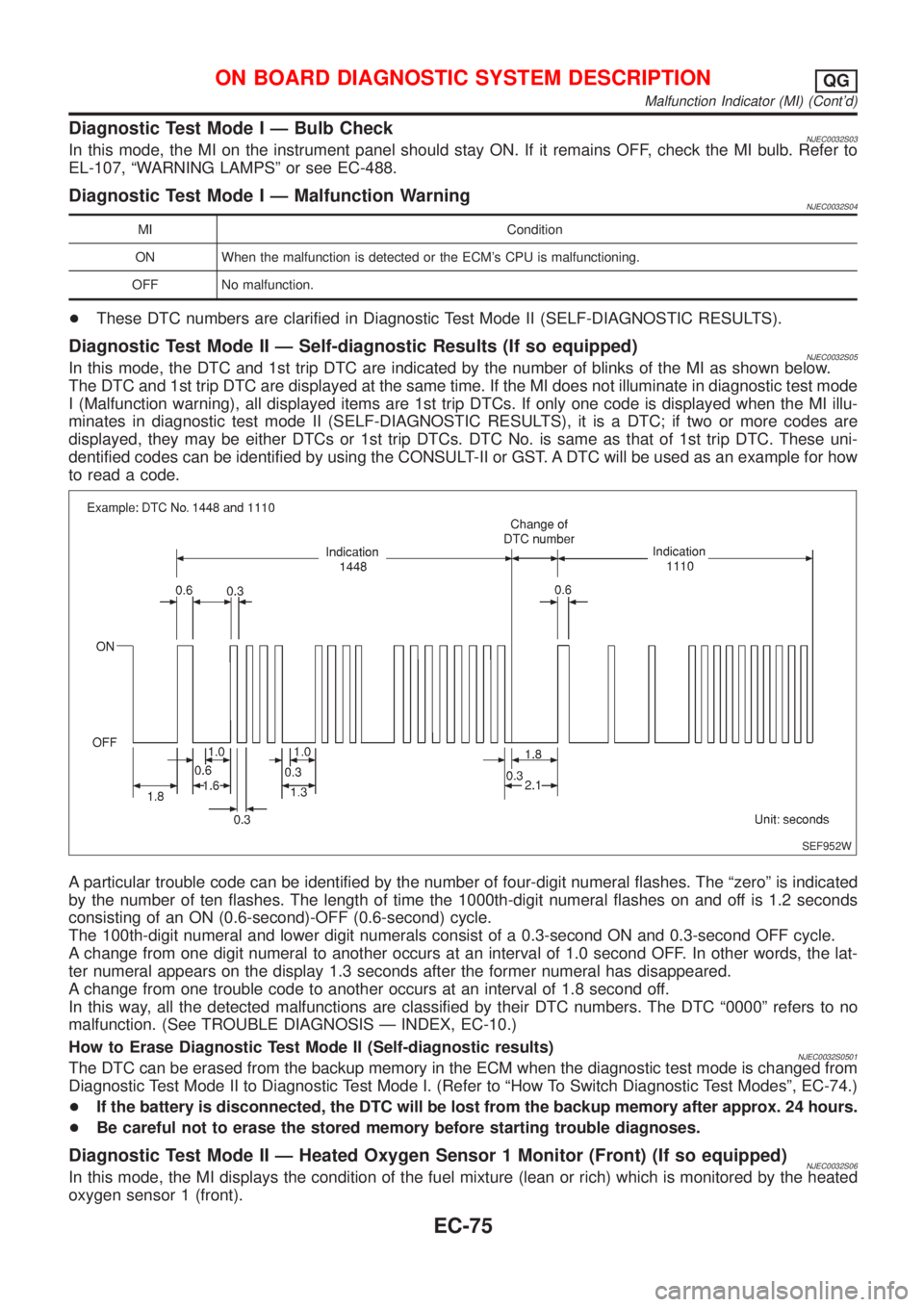
Diagnostic Test Mode II Ð Self-diagnostic Results (If so equipped)NJEC0032S05In this mode, the DTC and 1st trip DTC are indicated by the number of blinks of the MI as shown below.
The DTC and 1st trip DTC are displayed at the same time. If the MI does not illuminate in diagnostic test mode
I (Malfunction warning), all displayed items are 1st trip DTCs. If only one code is displayed when the MI illu-
minates in diagnostic test mode II (SELF-DIAGNOSTIC RESULTS), it is a DTC; if two or more codes are
displayed, they may be either DTCs or 1st trip DTCs. DTC No. is same as that of 1st trip DTC. These uni-
dentified codes can be identified by using the CONSULT-II or GST. A DTC will be used as an example for how
to read a code.
SEF952W
A particular trouble code can be identified by the number of four-digit numeral flashes. The ªzeroº is indicated
by the number of ten flashes. The length of time the 1000th-digit numeral flashes on and off is 1.2 seconds
consisting of an ON (0.6-second)-OFF (0.6-second) cycle.
The 100th-digit numeral and lower digit numerals consist of a 0.3-second ON and 0.3-second OFF cycle.
A change from one digit numeral to another occurs at an interval of 1.0 second OFF. In other words, the lat-
ter numeral appears on the display 1.3 seconds after the former numeral has disappeared.
A change from one trouble code to another occurs at an interval of 1.8 second off.
In this way, all the detected malfunctions are classified by their DTC numbers. The DTC ª0000º refers to no
malfunction. (See TROUBLE DIAGNOSIS Ð INDEX, EC-10.)
How to Erase Diagnostic Test Mode II (Self-diagnostic results)
NJEC0032S0501The DTC can be erased from the backup memory in the ECM when the diagnostic test mode is changed from
Diagnostic Test Mode II to Diagnostic Test Mode I. (Refer to ªHow To Switch Diagnostic Test Modesº, EC-74.)
+If the battery is disconnected, the DTC will be lost from the backup memory after approx. 24 hours.
+Be careful not to erase the stored memory before starting trouble diagnoses.
Diagnostic Test Mode II Ð Heated Oxygen Sensor 1 Monitor (Front) (If so equipped)NJEC0032S06In this mode, the MI displays the condition of the fuel mixture (lean or rich) which is monitored by the heated
oxygen sensor 1 (front).
ON BOARD DIAGNOSTIC SYSTEM DESCRIPTIONQG
Malfunction Indicator (MI) (Cont'd)
EC-75
Page 378 of 2493
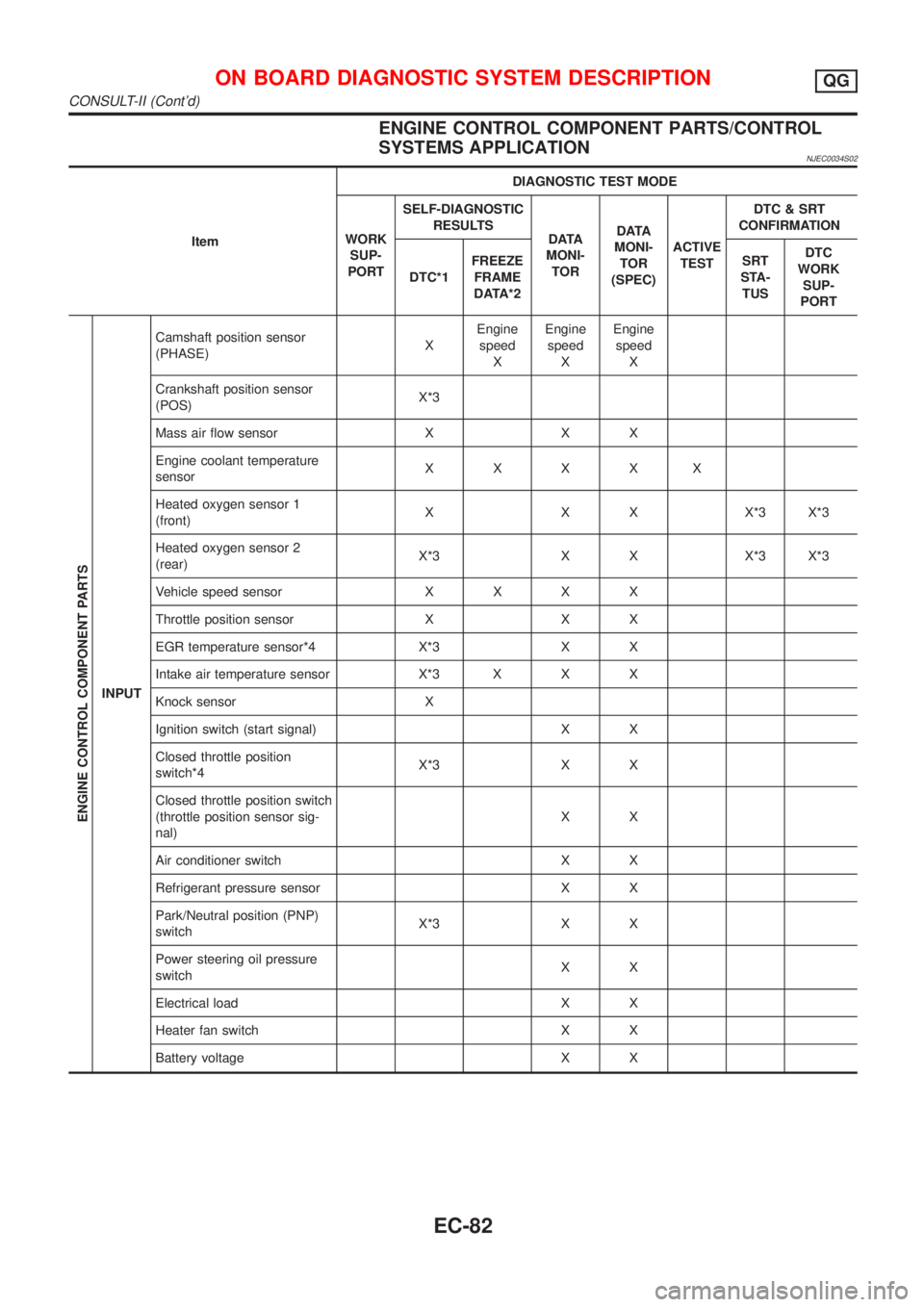
ENGINE CONTROL COMPONENT PARTS/CONTROL
SYSTEMS APPLICATION
NJEC0034S02
ItemDIAGNOSTIC TEST MODE
WORK
SUP-
PORTSELF-DIAGNOSTIC
RESULTS
D ATA
MONI-
TORD ATA
MONI-
TOR
(SPEC)ACTIVE
TESTDTC & SRT
CONFIRMATION
DTC*1FREEZE
FRAME
DATA*2SRT
STA-
TUSDTC
WORK
SUP-
PORT
ENGINE CONTROL COMPONENT PARTS
INPUTCamshaft position sensor
(PHASE)XEngine
speed
XEngine
speed
XEngine
speed
X
Crankshaft position sensor
(POS)X*3
Mass air flow sensor X X X
Engine coolant temperature
sensorXXXXX
Heated oxygen sensor 1
(front)X X X X*3 X*3
Heated oxygen sensor 2
(rear)X*3 X X X*3 X*3
Vehicle speed sensorXXXX
Throttle position sensor X X X
EGR temperature sensor*4 X*3 X X
Intake air temperature sensor X*3 X X X
Knock sensor X
Ignition switch (start signal) X X
Closed throttle position
switch*4X*3 X X
Closed throttle position switch
(throttle position sensor sig-
nal)XX
Air conditioner switch X X
Refrigerant pressure sensor X X
Park/Neutral position (PNP)
switchX*3 X X
Power steering oil pressure
switchXX
Electrical load X X
Heater fan switch X X
Battery voltage X X
ON BOARD DIAGNOSTIC SYSTEM DESCRIPTIONQG
CONSULT-II (Cont'd)
EC-82
Page 382 of 2493
![NISSAN ALMERA N16 2001 Electronic Owners Guide Monitored item [Unit]ECM
input
signalsMain
signalsDescription Remarks
HO2S2 MNTR (B1)
[RICH/LEAN]j+Display of heated oxygen sensor 2 (rear)
signal:
RICH ... means the amount of oxygen after
three way](/img/5/57351/w960_57351-381.png "NISSAN ALMERA N16 2001 Electronic Owners Guide Monitored item [Unit]ECM
input
signalsMain
signalsDescription Remarks
HO2S2 MNTR (B1)
[RICH/LEAN]j+Display of heated oxygen sensor 2 (rear)
signal:
RICH ... means the amount of oxygen after
three way")
Monitored item [Unit]ECM
input
signalsMain
signalsDescription Remarks
HO2S2 MNTR (B1)
[RICH/LEAN]j+Display of heated oxygen sensor 2 (rear)
signal:
RICH ... means the amount of oxygen after
three way catalyst is relatively small.
LEAN ... means the amount of oxygen after
three way catalyst is relatively large.+When the engine is stopped, a cer-
tain value is indicated.
VHCL SPEED SE
[km/h] or [mph]jj+The vehicle speed computed from the
vehicle speed sensor signal is displayed.
BATTERY VOLT [V]j+The power supply voltage of ECM is dis-
played.
THRTL POS SEN [V]jj+The throttle position sensor signal voltage is
displayed.
FUEL T/TMP SE
[ÉC] or [ÉF]*+The fuel temperature judged from the fuel
tank temperature sensor signal voltage is
displayed.
INT/A TEMP SE
[ÉC] or [ÉF]j+The intake air temperature determined by
the signal voltage of the intake air tempera-
ture sensor is indicated.
EGR TEMP SEN [V]*jj+The signal voltage of the EGR temperature
sensor is displayed.
START SIGNAL
[ON/OFF]jj+Indicates [ON/OFF] condition from the
starter signal.+After starting the engine, [OFF] is
displayed regardless of the starter
signal.
CLSD THL POS
[ON/OFF]jj+Indicates idle position [ON/OFF] computed
by ECM according to the throttle position
sensor signal.
CLSD THL/P SW
[ON/OFF]*j+Indicates mechanical contact [ON/OFF]
condition of the closed throttle position
switch.
AIR COND SIG
[ON/OFF]jj+Indicates [ON/OFF] condition of the air con-
ditioner switch as determined by the air
conditioning signal.
P/N POSI SW
[ON/OFF]jj+Indicates [ON/OFF] condition from the PNP
switch signal.
PW/ST SIGNAL
[ON/OFF]jj+Indicates [ON/OFF] condition of the power
steering oil pressure switch determined by
the power steering oil pressure switch sig-
nal.
LOAD SIGNAL
[ON/OFF]jj+Indicates [ON/OFF] condition from the elec-
trical load signal and/or lighting switch.
ON ... rear defogger is operating and/or
lighting switch is on.
OFF ... rear defogger is not operating and
lighting switch is not on.
IGNITION SW
[ON/OFF]j+Indicates [ON/OFF] condition from ignition
switch.
HEATER FAN SW
[ON/OFF]j+Indicates [ON/OFF] condition from the
heater fan switch.
INJ PULSE-B1
[msec]j+Indicates the actual fuel injection pulse
width compensated by ECM according to
the input signals.+When the engine is stopped, a cer-
tain computed value is indicated.
ON BOARD DIAGNOSTIC SYSTEM DESCRIPTIONQG
CONSULT-II (Cont'd)
EC-86
Page 420 of 2493
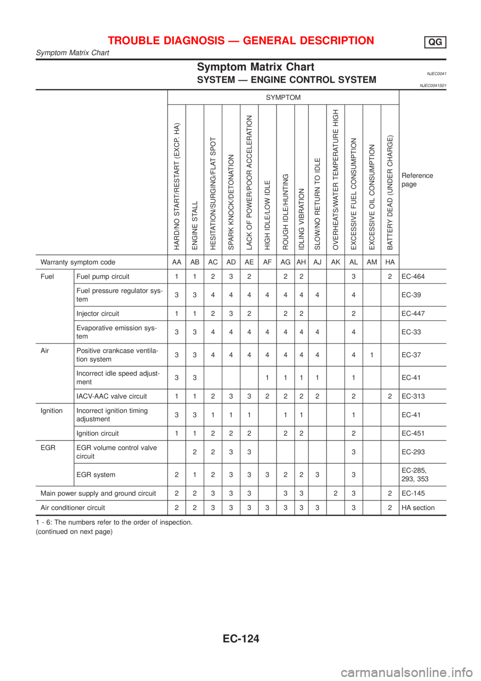
Symptom Matrix ChartNJEC0041SYSTEM Ð ENGINE CONTROL SYSTEMNJEC0041S01
SYMPTOM
Reference
page
HARD/NO START/RESTART (EXCP. HA)
ENGINE STALL
HESITATION/SURGING/FLAT SPOT
SPARK KNOCK/DETONATION
LACK OF POWER/POOR ACCELERATION
HIGH IDLE/LOW IDLE
ROUGH IDLE/HUNTING
IDLING VIBRATION
SLOW/NO RETURN TO IDLE
OVERHEATS/WATER TEMPERATURE HIGH
EXCESSIVE FUEL CONSUMPTION
EXCESSIVE OIL CONSUMPTION
BATTERY DEAD (UNDER CHARGE)
Warranty symptom code AA AB AC AD AE AF AG AH AJ AK AL AM HA
Fuel Fuel pump circuit11232 22 3 2EC-464
Fuel pressure regulator sys-
tem334444444 4EC-39
Injector circuit11232 22 2EC-447
Evaporative emission sys-
tem334444444 4EC-33
Air Positive crankcase ventila-
tion system334444444 41EC-37
Incorrect idle speed adjust-
ment3 3 1 1 1 1 1 EC-41
IACV-AAC valve circuit112332222 2 2EC-313
Ignition Incorrect ignition timing
adjustment33111 11 1EC-41
Ignition circuit11222 22 2EC-451
EGR EGR volume control valve
circuit2233 3EC-293
EGR system212333223 3EC-285,
293, 353
Main power supply and ground circuit22333 33 23 2EC-145
Air conditioner circuit223333333 3 2HAsection
1 - 6: The numbers refer to the order of inspection.
(continued on next page)
TROUBLE DIAGNOSIS Ð GENERAL DESCRIPTIONQG
Symptom Matrix Chart
EC-124
Page 421 of 2493
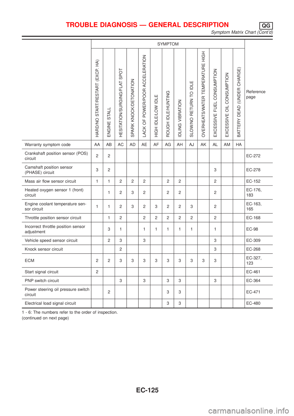
SYMPTOM
Reference
page
HARD/NO START/RESTART (EXCP. HA)
ENGINE STALL
HESITATION/SURGING/FLAT SPOT
SPARK KNOCK/DETONATION
LACK OF POWER/POOR ACCELERATION
HIGH IDLE/LOW IDLE
ROUGH IDLE/HUNTING
IDLING VIBRATION
SLOW/NO RETURN TO IDLE
OVERHEATS/WATER TEMPERATURE HIGH
EXCESSIVE FUEL CONSUMPTION
EXCESSIVE OIL CONSUMPTION
BATTERY DEAD (UNDER CHARGE)
Warranty symptom code AA AB AC AD AE AF AG AH AJ AK AL AM HA
Crankshaft position sensor (POS)
circuit22EC-272
Camshaft position sensor
(PHASE) circuit3 2 3 EC-278
Mass air flow sensor circuit11222 22 2EC-152
Heated oxygen sensor 1 (front)
circuit1232 22 2EC-176,
183
Engine coolant temperature sen-
sor circuit112323223 2EC-163,
165
Throttle position sensor circuit 1 222222 2EC-168
Incorrect throttle position sensor
adjustment31 11111 1EC-98
Vehicle speed sensor circuit 2 3 3 3 EC-309
Knock sensor circuit 2 3 EC-268
ECM 22333333333EC-327,
123
Start signal circuit 2EC-461
PNP switch circuit 3 3 3 3 3 EC-364
Power steering oil pressure switch
circuit2 3 3 EC-471
Electrical load signal circuit 3 3 EC-480
1 - 6: The numbers refer to the order of inspection.
(continued on next page)
TROUBLE DIAGNOSIS Ð GENERAL DESCRIPTIONQG
Symptom Matrix Chart (Cont'd)
EC-125
Page 422 of 2493
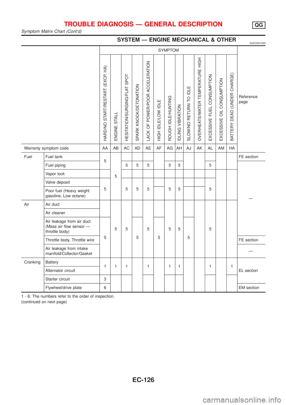
SYSTEM Ð ENGINE MECHANICAL & OTHERNJEC0041S03
SYMPTOM
Reference
page
HARD/NO START/RESTART (EXCP. HA)
ENGINE STALL
HESITATION/SURGING/FLAT SPOT
SPARK KNOCK/DETONATION
LACK OF POWER/POOR ACCELERATION
HIGH IDLE/LOW IDLE
ROUGH IDLE/HUNTING
IDLING VIBRATION
SLOW/NO RETURN TO IDLE
OVERHEATS/WATER TEMPERATURE HIGH
EXCESSIVE FUEL CONSUMPTION
EXCESSIVE OIL CONSUMPTION
BATTERY DEAD (UNDER CHARGE)
Warranty symptom code AA AB AC AD AE AF AG AH AJ AK AL AM HA
Fuel Fuel tank
5
5FE section
Fuel piping 5 5 5 5 5 5
Ð Vapor lock
Valve deposit
5 555 55 5
Poor fuel (Heavy weight
gasoline, Low octane)
Air Air duct
55555 5 Air cleaner
Air leakage from air duct
(Mass air flow sensor Ð
throttle body)
5555
Throttle body, Throttle wireFE section
Air leakage from intake
manifold/Collector/GasketÐ
Cranking Battery
111111 11
EL section Alternator circuit
Starter circuit 3
Flywheel/drive plate 6EM section
1 - 6: The numbers refer to the order of inspection.
(continued on next page)
TROUBLE DIAGNOSIS Ð GENERAL DESCRIPTIONQG
Symptom Matrix Chart (Cont'd)
EC-126
Page 423 of 2493
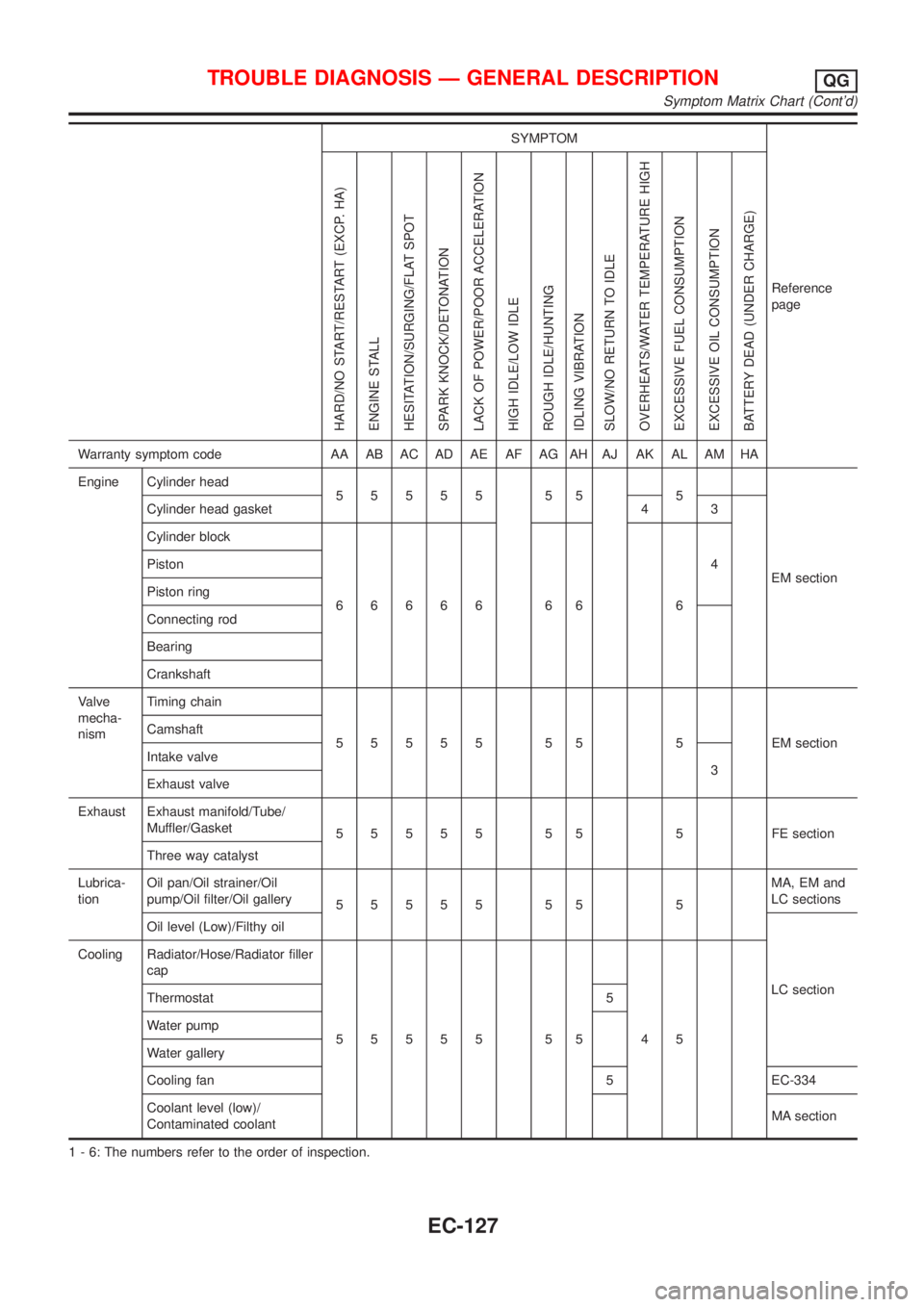
SYMPTOM
Reference
page
HARD/NO START/RESTART (EXCP. HA)
ENGINE STALL
HESITATION/SURGING/FLAT SPOT
SPARK KNOCK/DETONATION
LACK OF POWER/POOR ACCELERATION
HIGH IDLE/LOW IDLE
ROUGH IDLE/HUNTING
IDLING VIBRATION
SLOW/NO RETURN TO IDLE
OVERHEATS/WATER TEMPERATURE HIGH
EXCESSIVE FUEL CONSUMPTION
EXCESSIVE OIL CONSUMPTION
BATTERY DEAD (UNDER CHARGE)
Warranty symptom code AA AB AC AD AE AF AG AH AJ AK AL AM HA
Engine Cylinder head
55555 55 5
EM section Cylinder head gasket 4 3
Cylinder block
66666 66 64 Piston
Piston ring
Connecting rod
Bearing
Crankshaft
Valve
mecha-
nismTiming chain
55555 55 5 EMsection Camshaft
Intake valve
3
Exhaust valve
Exhaust Exhaust manifold/Tube/
Muffler/Gasket
55555 55 5 FEsection
Three way catalyst
Lubrica-
tionOil pan/Oil strainer/Oil
pump/Oil filter/Oil gallery
55555 55 5MA, EM and
LC sections
Oil level (Low)/Filthy oil
LC section Cooling Radiator/Hose/Radiator filler
cap
55555 55 45 Thermostat 5
Water pump
Water gallery
Cooling fan 5 EC-334
Coolant level (low)/
Contaminated coolantMA section
1 - 6: The numbers refer to the order of inspection.
TROUBLE DIAGNOSIS Ð GENERAL DESCRIPTIONQG
Symptom Matrix Chart (Cont'd)
EC-127
Page 424 of 2493
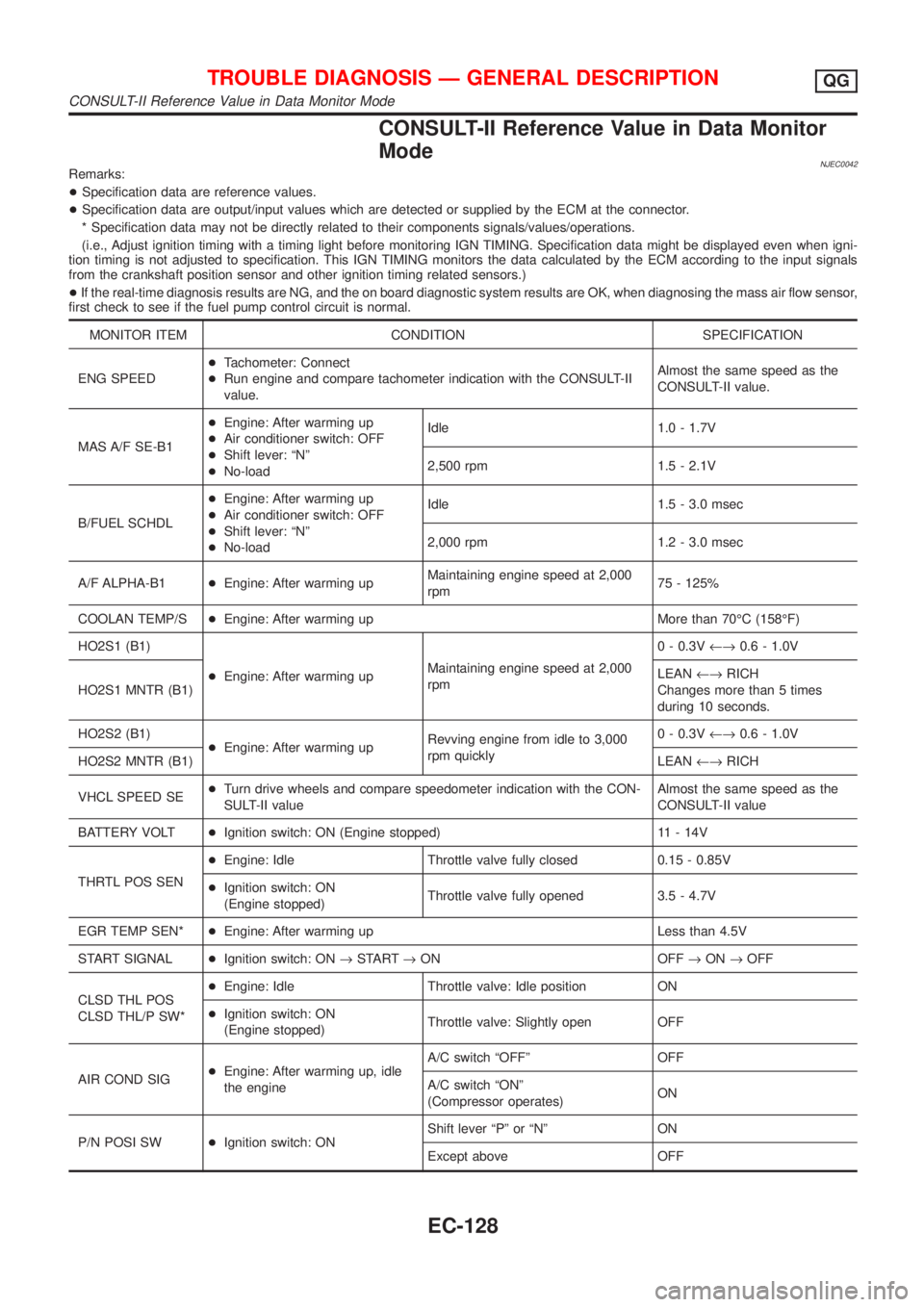
CONSULT-II Reference Value in Data Monitor
Mode
NJEC0042Remarks:
+Specification data are reference values.
+Specification data are output/input values which are detected or supplied by the ECM at the connector.
* Specification data may not be directly related to their components signals/values/operations.
(i.e., Adjust ignition timing with a timing light before monitoring IGN TIMING. Specification data might be displayed even when igni-
tion timing is not adjusted to specification. This IGN TIMING monitors the data calculated by the ECM according to the input signals
from the crankshaft position sensor and other ignition timing related sensors.)
+If the real-time diagnosis results are NG, and the on board diagnostic system results are OK, when diagnosing the mass air flow sensor,
first check to see if the fuel pump control circuit is normal.
MONITOR ITEM CONDITION SPECIFICATION
ENG SPEED+Tachometer: Connect
+Run engine and compare tachometer indication with the CONSULT-II
value.Almost the same speed as the
CONSULT-II value.
MAS A/F SE-B1+Engine: After warming up
+Air conditioner switch: OFF
+Shift lever: ªNº
+No-loadIdle 1.0 - 1.7V
2,500 rpm 1.5 - 2.1V
B/FUEL SCHDL+Engine: After warming up
+Air conditioner switch: OFF
+Shift lever: ªNº
+No-loadIdle 1.5 - 3.0 msec
2,000 rpm 1.2 - 3.0 msec
A/F ALPHA-B1+Engine: After warming upMaintaining engine speed at 2,000
rpm75 - 125%
COOLAN TEMP/S+Engine: After warming up More than 70ÉC (158ÉF)
HO2S1 (B1)
+Engine: After warming upMaintaining engine speed at 2,000
rpm0 - 0.3V¨0.6 - 1.0V
HO2S1 MNTR (B1)LEAN¨RICH
Changes more than 5 times
during 10 seconds.
HO2S2 (B1)
+Engine: After warming upRevving engine from idle to 3,000
rpm quickly0 - 0.3V¨0.6 - 1.0V
HO2S2 MNTR (B1)LEAN¨RICH
VHCL SPEED SE+Turn drive wheels and compare speedometer indication with the CON-
SULT-II valueAlmost the same speed as the
CONSULT-II value
BATTERY VOLT+Ignition switch: ON (Engine stopped) 11 - 14V
THRTL POS SEN+Engine: Idle Throttle valve fully closed 0.15 - 0.85V
+Ignition switch: ON
(Engine stopped)Throttle valve fully opened 3.5 - 4.7V
EGR TEMP SEN*+Engine: After warming up Less than 4.5V
START SIGNAL+Ignition switch: ON®START®ON OFF®ON®OFF
CLSD THL POS
CLSD THL/P SW*+Engine: Idle Throttle valve: Idle position ON
+Ignition switch: ON
(Engine stopped)Throttle valve: Slightly open OFF
AIR COND SIG+Engine: After warming up, idle
the engineA/C switch ªOFFº OFF
A/C switch ªONº
(Compressor operates)ON
P/N POSI SW+Ignition switch: ONShift lever ªPº or ªNº ON
Except above OFF
TROUBLE DIAGNOSIS Ð GENERAL DESCRIPTIONQG
CONSULT-II Reference Value in Data Monitor Mode
EC-128
Page 429 of 2493
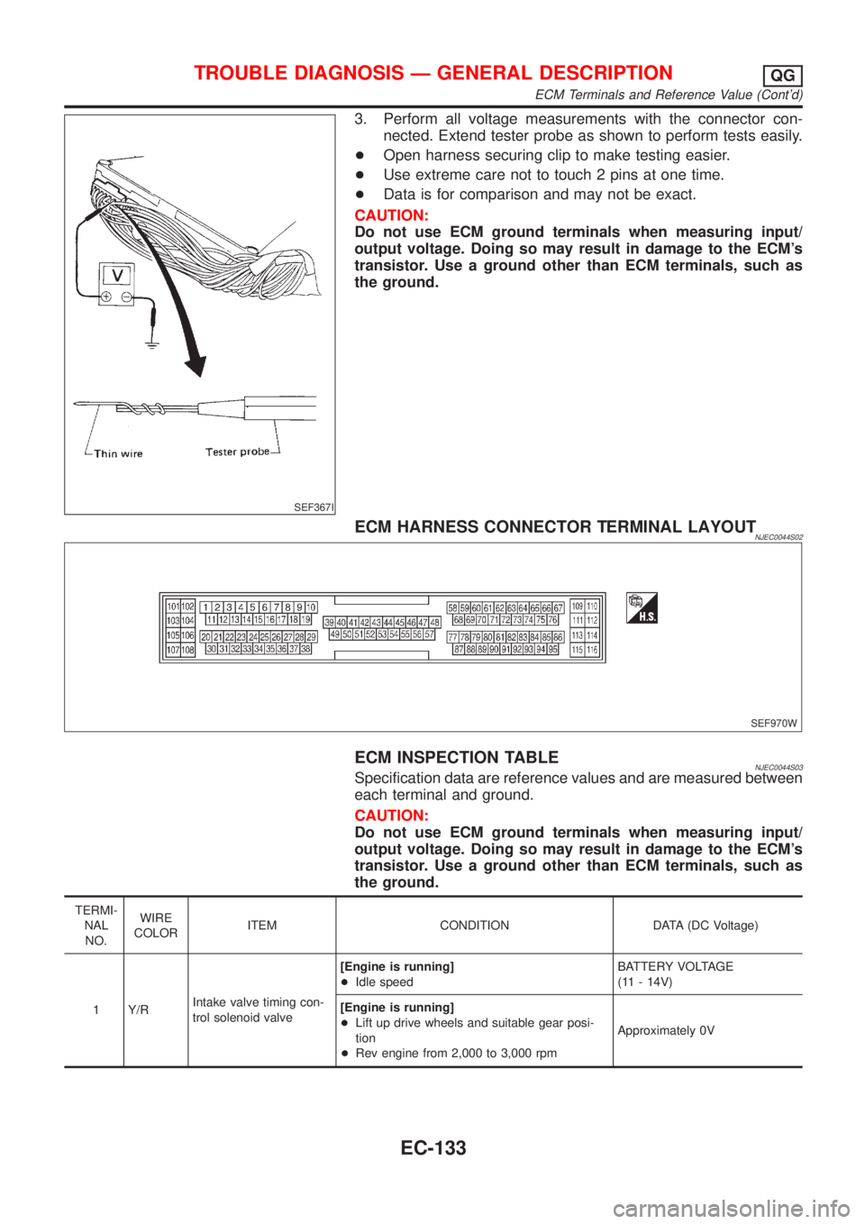
SEF367I
3. Perform all voltage measurements with the connector con-
nected. Extend tester probe as shown to perform tests easily.
+Open harness securing clip to make testing easier.
+Use extreme care not to touch 2 pins at one time.
+Data is for comparison and may not be exact.
CAUTION:
Do not use ECM ground terminals when measuring input/
output voltage. Doing so may result in damage to the ECM's
transistor. Use a ground other than ECM terminals, such as
the ground.
ECM HARNESS CONNECTOR TERMINAL LAYOUTNJEC0044S02
SEF970W
ECM INSPECTION TABLENJEC0044S03Specification data are reference values and are measured between
each terminal and ground.
CAUTION:
Do not use ECM ground terminals when measuring input/
output voltage. Doing so may result in damage to the ECM's
transistor. Use a ground other than ECM terminals, such as
the ground.
TERMI-
NAL
NO.WIRE
COLORITEM CONDITION DATA (DC Voltage)
1 Y/RIntake valve timing con-
trol solenoid valve[Engine is running]
+Idle speedBATTERY VOLTAGE
(11 - 14V)
[Engine is running]
+Lift up drive wheels and suitable gear posi-
tion
+Rev engine from 2,000 to 3,000 rpmApproximately 0V
TROUBLE DIAGNOSIS Ð GENERAL DESCRIPTIONQG
ECM Terminals and Reference Value (Cont'd)
EC-133