EL page 71 NISSAN ALMERA N16 2001 Electronic Manual PDF
[x] Cancel search | Manufacturer: NISSAN, Model Year: 2001, Model line: ALMERA N16, Model: NISSAN ALMERA N16 2001Pages: 2493, PDF Size: 66.97 MB
Page 1223 of 2493
CONSULT-IINJAT0022After performing ªSELF-DIAGNOSTIC PROCEDURE (WITH CON-
SULT-II)º (AT-37), place check marks for results on the ªDIAGNOS-
TIC WORKSHEETº, AT-69. Reference pages are provided follow-
ing the items.
NOTICE:
1) The CONSULT-II electrically displays shift timing and lock-up
timing (that is, operation timing of each solenoid).
Check for time difference between actual shift timing and the
CONSULT-II display. If the difference is noticeable, mechani-
cal parts (except solenoids, sensors, etc.) may be malfunction-
ing. Check mechanical parts using applicable diagnostic pro-
cedures.
2) Shift schedule (which implies gear position) displayed on
CONSULT-II and that indicated in Service Manual may differ
slightly. This occurs because of the following reasons:
+Actual shift schedule has more or less tolerance or allowance,
+Shift schedule indicated in Service Manual refers to the point
where shifts start, and
+Gear position displayed on CONSULT-II indicates the point
where shifts are completed.
3) Shift solenoid valve ªAº or ªBº is displayed on CONSULT-II at
the start of shifting. Gear position is displayed upon completion
of shifting (which is computed by TCM).
4) Additional CONSULT-II information can be found in the Opera-
tion Manual supplied with the CONSULT-II unit.
SAT580J
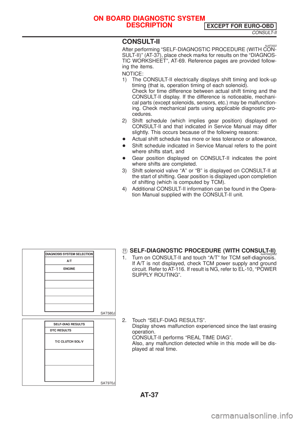
SELF-DIAGNOSTIC PROCEDURE (WITH CONSULT-II)NJAT0022S021. Turn on CONSULT-II and touch ªA/Tº for TCM self-diagnosis.
If A/T is not displayed, check TCM power supply and ground
circuit. Refer to AT-116. If result is NG, refer to EL-10, ªPOWER
SUPPLY ROUTINGº.
SAT970J
2. Touch ªSELF-DIAG RESULTSº.
Display shows malfunction experienced since the last erasing
operation.
CONSULT-II performs ªREAL TIME DIAGº.
Also, any malfunction detected while in this mode will be dis-
played at real time.
ON BOARD DIAGNOSTIC SYSTEM
DESCRIPTION
EXCEPT FOR EURO-OBD
CONSULT-II
AT-37
Page 1234 of 2493
IntroductionNJAT0251The A/T system has two self-diagnostic systems.
The first is the emission-related on board diagnostic system (EURO-OBD) performed by the TCM in combi-
nation with the ECM. The malfunction is indicated by the MI (malfunction indicator) and is stored as a DTC in
the ECM memory but not the TCM memory.
The second is the TCM original self-diagnosis indicated by the O/D OFF indicator lamp. The malfunction is
stored in the TCM memory. The detected items are overlapped with EURO-OBD self-diagnostic items. For
detail, refer to AT-53.
EURO-OBD Function for A/T SystemNJAT0252The ECM provides emission-related on board diagnostic (EURO-OBD) functions for the A/T system. One
function is to receive a signal from the TCM used with EURO-OBD-related parts of the A/T system. The sig-
nal is sent to the ECM when a malfunction occurs in the corresponding EURO-OBD-related part. The other
function is to indicate a diagnostic result by means of the MI (malfunction indicator) on the instrument panel.
Sensors, switches and solenoid valves are used as sensing elements.
The MI automatically illuminates in One or Two Trip Detection Logic when a malfunction is sensed in relation
to A/T system parts.
One or Two Trip Detection Logic of EURO-OBDNJAT0253ONE TRIP DETECTION LOGICNJAT0253S01If a malfunction is sensed during the first test drive, the MI will illuminate and the malfunction will be stored
in the ECM memory as a DTC. The TCM is not provided with such a memory function.
TWO TRIP DETECTION LOGICNJAT0253S02When a malfunction is sensed during the first test drive, it is stored in the ECM memory as a 1st trip DTC
(diagnostic trouble code) or 1st trip freeze frame data. At this point, the MI will not illuminate. Ð First Trip
If the same malfunction as that experienced during the first test drive is sensed during the second test drive,
the MI will illuminate. Ð Second Trip
A/T-related parts for which the MI illuminates during the first or second test drive are listed below.
ItemsMI
One trip detection Two trip detection
Shift solenoid valve A Ð DTC: P0750 X
Shift solenoid valve B Ð DTC: P0755 X
Throttle position sensor or switch Ð DTC: P1705 X
Except aboveX
The ªtripº in the ªOne or Two Trip Detection Logicº means a driving mode in which self-diagnosis is performed
during vehicle operation.
EURO-OBD Diagnostic Trouble Code (DTC)NJAT0254HOW TO READ DTC AND 1ST TRIP DTCNJAT0254S01DTC and 1st trip DTC can be read by the following methods.
(
with CONSULT-II orGST)CONSULT-II or GST (Generic Scan Tool) Examples: P0705, P0710, P0720,
P0725, etc.
These DTCs are prescribed by SAE J2012.
(CONSULT-II also displays the malfunctioning component or system.)
+1st trip DTC No. is the same as DTC No.
+Output of the diagnostic trouble code indicates that the indicated circuit has a malfunction.
However, in case of the Mode II and GST they do not indicate whether the malfunction is still
occurring or occurred in the past and returned to normal.
CONSULT-II can identify them as shown below. Therefore, using CONSULT-II (if available) is rec-
ommended.
A sample of CONSULT-II display for DTC is shown in the following page. DTC or 1st trip DTC of a malfunc-
tion is displayed in SELF DIAGNOSIS mode for ªENGINEº with CONSULT-II. Time data indicates how many
times the vehicle was driven after the last detection of a DTC.
ON BOARD DIAGNOSTIC SYSTEM DESCRIPTIONEURO-OBD
Introduction
AT-48
Page 1238 of 2493
SAT964I
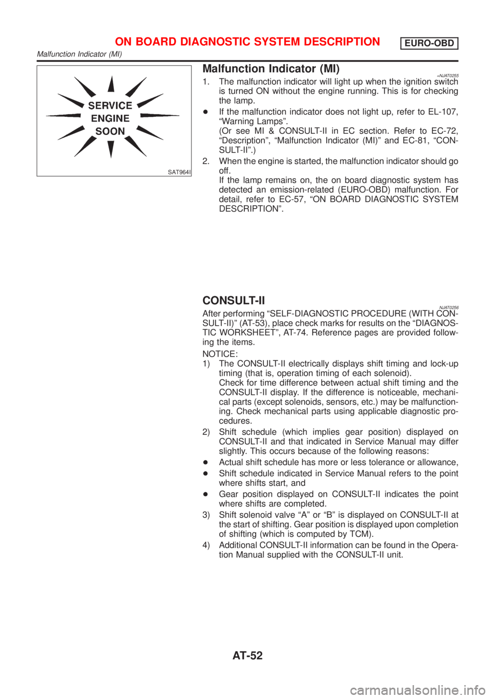
Malfunction Indicator (MI)=NJAT02551. The malfunction indicator will light up when the ignition switch
is turned ON without the engine running. This is for checking
the lamp.
+If the malfunction indicator does not light up, refer to EL-107,
ªWarning Lampsº.
(Or see MI & CONSULT-II in EC section. Refer to EC-72,
ªDescriptionº, ªMalfunction Indicator (MI)º and EC-81, ªCON-
SULT-IIº.)
2. When the engine is started, the malfunction indicator should go
off.
If the lamp remains on, the on board diagnostic system has
detected an emission-related (EURO-OBD) malfunction. For
detail, refer to EC-57, ªON BOARD DIAGNOSTIC SYSTEM
DESCRIPTIONº.
CONSULT-IINJAT0256After performing ªSELF-DIAGNOSTIC PROCEDURE (WITH CON-
SULT-II)º (AT-53), place check marks for results on the ªDIAGNOS-
TIC WORKSHEETº, AT-74. Reference pages are provided follow-
ing the items.
NOTICE:
1) The CONSULT-II electrically displays shift timing and lock-up
timing (that is, operation timing of each solenoid).
Check for time difference between actual shift timing and the
CONSULT-II display. If the difference is noticeable, mechani-
cal parts (except solenoids, sensors, etc.) may be malfunction-
ing. Check mechanical parts using applicable diagnostic pro-
cedures.
2) Shift schedule (which implies gear position) displayed on
CONSULT-II and that indicated in Service Manual may differ
slightly. This occurs because of the following reasons:
+Actual shift schedule has more or less tolerance or allowance,
+Shift schedule indicated in Service Manual refers to the point
where shifts start, and
+Gear position displayed on CONSULT-II indicates the point
where shifts are completed.
3) Shift solenoid valve ªAº or ªBº is displayed on CONSULT-II at
the start of shifting. Gear position is displayed upon completion
of shifting (which is computed by TCM).
4) Additional CONSULT-II information can be found in the Opera-
tion Manual supplied with the CONSULT-II unit.
ON BOARD DIAGNOSTIC SYSTEM DESCRIPTIONEURO-OBD
Malfunction Indicator (MI)
AT-52
Page 1265 of 2493
SAT513G
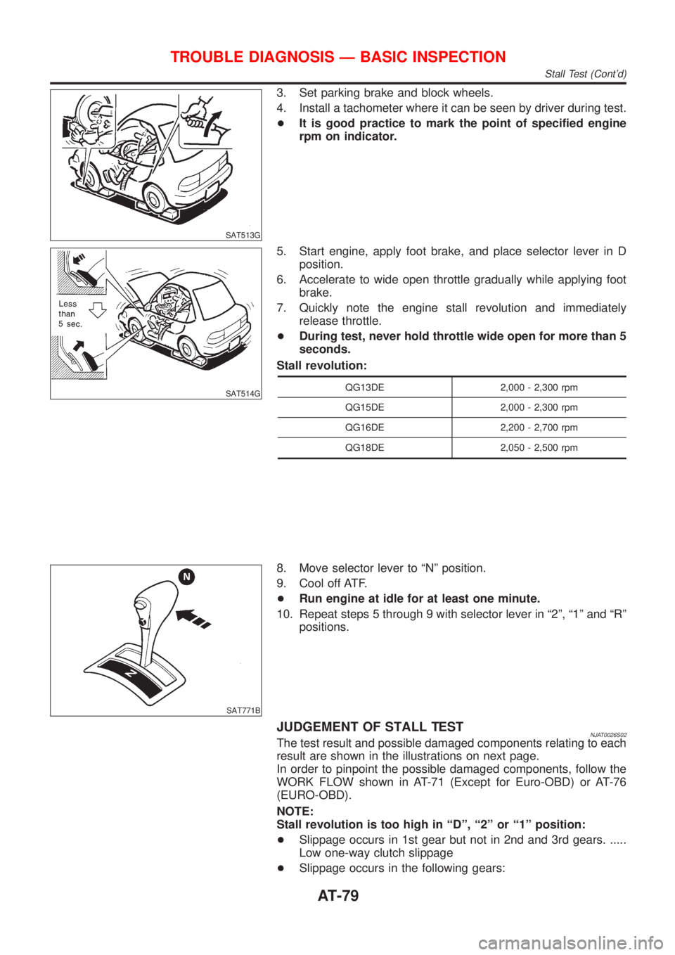
3. Set parking brake and block wheels.
4. Install a tachometer where it can be seen by driver during test.
+It is good practice to mark the point of specified engine
rpm on indicator.
SAT514G
5. Start engine, apply foot brake, and place selector lever in D
position.
6. Accelerate to wide open throttle gradually while applying foot
brake.
7. Quickly note the engine stall revolution and immediately
release throttle.
+During test, never hold throttle wide open for more than 5
seconds.
Stall revolution:
QG13DE 2,000 - 2,300 rpm
QG15DE 2,000 - 2,300 rpm
QG16DE 2,200 - 2,700 rpm
QG18DE 2,050 - 2,500 rpm
SAT771B
8. Move selector lever to ªNº position.
9. Cool off ATF.
+Run engine at idle for at least one minute.
10. Repeat steps 5 through 9 with selector lever in ª2º, ª1º and ªRº
positions.
JUDGEMENT OF STALL TESTNJAT0026S02The test result and possible damaged components relating to each
result are shown in the illustrations on next page.
In order to pinpoint the possible damaged components, follow the
WORK FLOW shown in AT-71 (Except for Euro-OBD) or AT-76
(EURO-OBD).
NOTE:
Stall revolution is too high in ªDº, ª2º or ª1º position:
+Slippage occurs in 1st gear but not in 2nd and 3rd gears. .....
Low one-way clutch slippage
+Slippage occurs in the following gears:
TROUBLE DIAGNOSIS Ð BASIC INSPECTION
Stall Test (Cont'd)
AT-79
Page 1266 of 2493
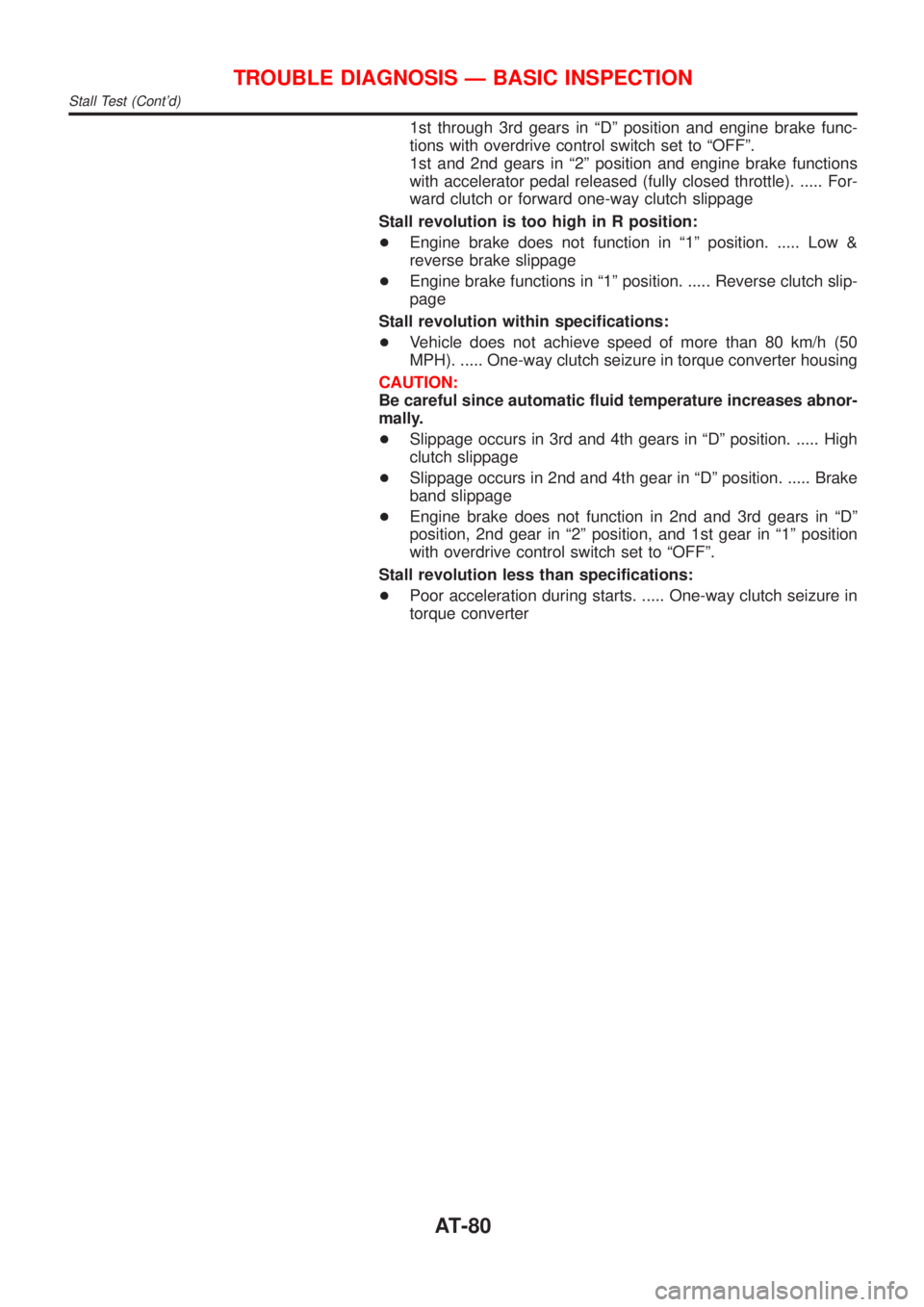
1st through 3rd gears in ªDº position and engine brake func-
tions with overdrive control switch set to ªOFFº.
1st and 2nd gears in ª2º position and engine brake functions
with accelerator pedal released (fully closed throttle). ..... For-
ward clutch or forward one-way clutch slippage
Stall revolution is too high in R position:
+Engine brake does not function in ª1º position. ..... Low &
reverse brake slippage
+Engine brake functions in ª1º position. ..... Reverse clutch slip-
page
Stall revolution within specifications:
+Vehicle does not achieve speed of more than 80 km/h (50
MPH). ..... One-way clutch seizure in torque converter housing
CAUTION:
Be careful since automatic fluid temperature increases abnor-
mally.
+Slippage occurs in 3rd and 4th gears in ªDº position. ..... High
clutch slippage
+Slippage occurs in 2nd and 4th gear in ªDº position. ..... Brake
band slippage
+Engine brake does not function in 2nd and 3rd gears in ªDº
position, 2nd gear in ª2º position, and 1st gear in ª1º position
with overdrive control switch set to ªOFFº.
Stall revolution less than specifications:
+Poor acceleration during starts. ..... One-way clutch seizure in
torque converter
TROUBLE DIAGNOSIS Ð BASIC INSPECTION
Stall Test (Cont'd)
AT-80
Page 1289 of 2493
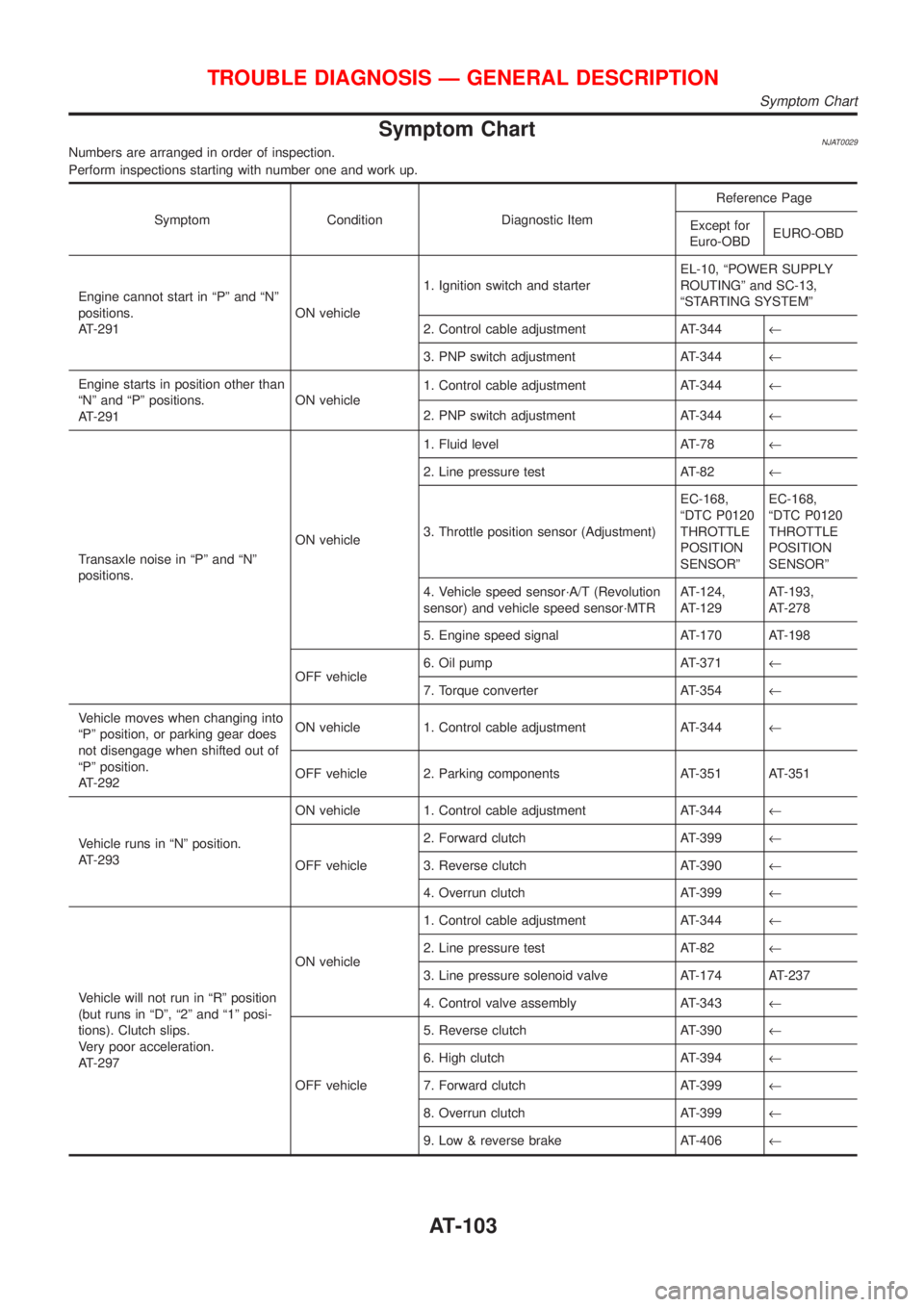
Symptom ChartNJAT0029Numbers are arranged in order of inspection.
Perform inspections starting with number one and work up.
Symptom Condition Diagnostic ItemReference Page
Except for
Euro-OBDEURO-OBD
Engine cannot start in ªPº and ªNº
positions.
AT-291ON vehicle1. Ignition switch and starterEL-10, ªPOWER SUPPLY
ROUTINGº and SC-13,
ªSTARTING SYSTEMº
2. Control cable adjustment AT-344¬
3. PNP switch adjustment AT-344¬
Engine starts in position other than
ªNº and ªPº positions.
AT-291ON vehicle1. Control cable adjustment AT-344¬
2. PNP switch adjustment AT-344¬
Transaxle noise in ªPº and ªNº
positions.ON vehicle1. Fluid level AT-78¬
2. Line pressure test AT-82¬
3. Throttle position sensor (Adjustment)EC-168,
ªDTC P0120
THROTTLE
POSITION
SENSORºEC-168,
ªDTC P0120
THROTTLE
POSITION
SENSORº
4. Vehicle speed sensor´A/T (Revolution
sensor) and vehicle speed sensor´MTRAT-124,
AT-129AT-193,
AT-278
5. Engine speed signal AT-170 AT-198
OFF vehicle6. Oil pump AT-371¬
7. Torque converter AT-354¬
Vehicle moves when changing into
ªPº position, or parking gear does
not disengage when shifted out of
ªPº position.
AT-292ON vehicle 1. Control cable adjustment AT-344¬
OFF vehicle 2. Parking components AT-351 AT-351
Vehicle runs in ªNº position.
AT-293ON vehicle 1. Control cable adjustment AT-344¬
OFF vehicle2. Forward clutch AT-399¬
3. Reverse clutch AT-390¬
4. Overrun clutch AT-399¬
Vehicle will not run in ªRº position
(but runs in ªDº, ª2º and ª1º posi-
tions). Clutch slips.
Very poor acceleration.
AT-297ON vehicle1. Control cable adjustment AT-344¬
2. Line pressure test AT-82¬
3. Line pressure solenoid valve AT-174 AT-237
4. Control valve assembly AT-343¬
OFF vehicle5. Reverse clutch AT-390¬
6. High clutch AT-394¬
7. Forward clutch AT-399¬
8. Overrun clutch AT-399¬
9. Low & reverse brake AT-406¬
TROUBLE DIAGNOSIS Ð GENERAL DESCRIPTION
Symptom Chart
AT-103
Page 1290 of 2493
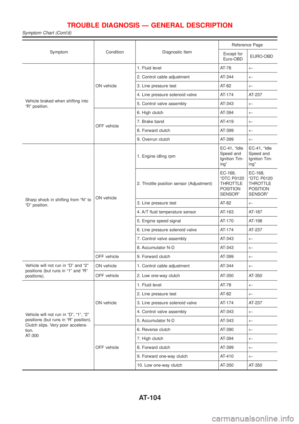
Symptom Condition Diagnostic ItemReference Page
Except for
Euro-OBDEURO-OBD
Vehicle braked when shifting into
ªRº position.ON vehicle1. Fluid level AT-78¬
2. Control cable adjustment AT-344¬
3. Line pressure test AT-82¬
4. Line pressure solenoid valve AT-174 AT-237
5. Control valve assembly AT-343¬
OFF vehicle6. High clutch AT-394¬
7. Brake band AT-419¬
8. Forward clutch AT-399¬
9. Overrun clutch AT-399¬
Sharp shock in shifting from ªNº to
ªDº position.ON vehicle1. Engine idling rpmEC-41, ªIdle
Speed and
Ignition Tim-
ingºEC-41, ªIdle
Speed and
Ignition Tim-
ingº
2. Throttle position sensor (Adjustment)EC-168,
ªDTC P0120
THROTTLE
POSITION
SENSORºEC-168,
ªDTC P0120
THROTTLE
POSITION
SENSORº
3. Line pressure test AT-82¬
4. A/T fluid temperature sensor AT-163 AT-187
5. Engine speed signal AT-170 AT-198
6. Line pressure solenoid valve AT-174 AT-237
7. Control valve assembly AT-343¬
8. Accumulator N-D AT-343¬
OFF vehicle 9. Forward clutch AT-399¬
Vehicle will not run in ªDº and ª2º
positions (but runs in ª1º and ªRº
positions).ON vehicle 1. Control cable adjustment AT-344¬
OFF vehicle 2. Low one-way clutch AT-350 AT-350
Vehicle will not run in ªDº, ª1º, ª2º
positions (but runs in ªRº position).
Clutch slips. Very poor accelera-
tion.
AT-300ON vehicle1. Fluid level AT-78¬
2. Line pressure test AT-82¬
3. Line pressure solenoid valve AT-174 AT-237
4. Control valve assembly AT-343¬
5. Accumulator N-D AT-343¬
OFF vehicle6. Reverse clutch AT-390¬
7. High clutch AT-394¬
8. Forward clutch AT-399¬
9. Forward one-way clutch AT-410¬
10. Low one-way clutch AT-350 AT-350
TROUBLE DIAGNOSIS Ð GENERAL DESCRIPTION
Symptom Chart (Cont'd)
AT-104
Page 1291 of 2493
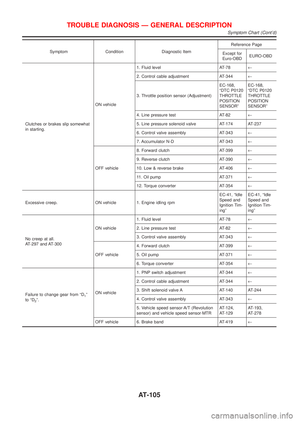
Symptom Condition Diagnostic ItemReference Page
Except for
Euro-OBDEURO-OBD
Clutches or brakes slip somewhat
in starting.ON vehicle1. Fluid level AT-78¬
2. Control cable adjustment AT-344¬
3. Throttle position sensor (Adjustment)EC-168,
ªDTC P0120
THROTTLE
POSITION
SENSORºEC-168,
ªDTC P0120
THROTTLE
POSITION
SENSORº
4. Line pressure test AT-82¬
5. Line pressure solenoid valve AT-174 AT-237
6. Control valve assembly AT-343¬
7. Accumulator N-D AT-343¬
OFF vehicle8. Forward clutch AT-399¬
9. Reverse clutch AT-390¬
10. Low & reverse brake AT-406¬
11. Oil pump AT-371¬
12. Torque converter AT-354¬
Excessive creep. ON vehicle 1. Engine idling rpmEC-41, ªIdle
Speed and
Ignition Tim-
ingºEC-41, ªIdle
Speed and
Ignition Tim-
ingº
No creep at all.
AT-297 and AT-300ON vehicle1. Fluid level AT-78¬
2. Line pressure test AT-82¬
3. Control valve assembly AT-343¬
OFF vehicle4. Forward clutch AT-399¬
5. Oil pump AT-371¬
6. Torque converter AT-354¬
Failure to change gear from ªD
1º
to ªD
2º.ON vehicle1. PNP switch adjustment AT-344¬
2. Control cable adjustment AT-344¬
3. Shift solenoid valve A AT-140 AT-244
4. Control valve assembly AT-343¬
5. Vehicle speed sensor´A/T (Revolution
sensor) and vehicle speed sensor´MTRAT-124,
AT-129AT-193,
AT-278
OFF vehicle 6. Brake band AT-419¬
TROUBLE DIAGNOSIS Ð GENERAL DESCRIPTION
Symptom Chart (Cont'd)
AT-105
Page 1292 of 2493
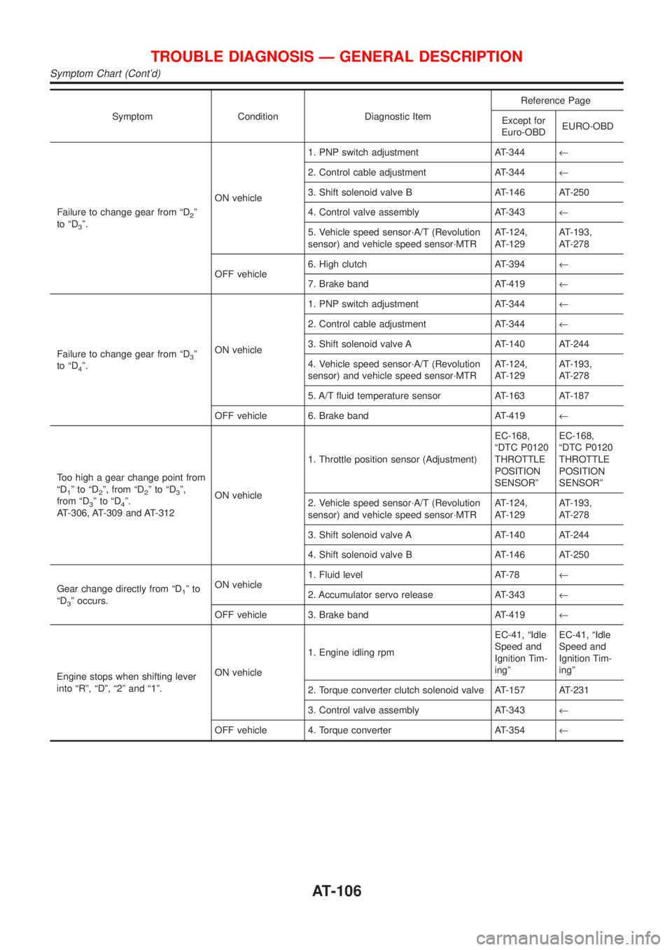
Symptom Condition Diagnostic ItemReference Page
Except for
Euro-OBDEURO-OBD
Failure to change gear from ªD
2º
to ªD
3º.ON vehicle1. PNP switch adjustment AT-344¬
2. Control cable adjustment AT-344¬
3. Shift solenoid valve B AT-146 AT-250
4. Control valve assembly AT-343¬
5. Vehicle speed sensor´A/T (Revolution
sensor) and vehicle speed sensor´MTRAT-124,
AT-129AT-193,
AT-278
OFF vehicle6. High clutch AT-394¬
7. Brake band AT-419¬
Failure to change gear from ªD
3º
to ªD
4º.ON vehicle1. PNP switch adjustment AT-344¬
2. Control cable adjustment AT-344¬
3. Shift solenoid valve A AT-140 AT-244
4. Vehicle speed sensor´A/T (Revolution
sensor) and vehicle speed sensor´MTRAT-124,
AT-129AT-193,
AT-278
5. A/T fluid temperature sensor AT-163 AT-187
OFF vehicle 6. Brake band AT-419¬
Too high a gear change point from
ªD
1ºtoªD2º, from ªD2ºtoªD3º,
from ªD
3ºtoªD4º.
AT-306, AT-309 and AT-312ON vehicle1. Throttle position sensor (Adjustment)EC-168,
ªDTC P0120
THROTTLE
POSITION
SENSORºEC-168,
ªDTC P0120
THROTTLE
POSITION
SENSORº
2. Vehicle speed sensor´A/T (Revolution
sensor) and vehicle speed sensor´MTRAT-124,
AT-129AT-193,
AT-278
3. Shift solenoid valve A AT-140 AT-244
4. Shift solenoid valve B AT-146 AT-250
Gear change directly from ªD
1ºto
ªD
3º occurs.ON vehicle1. Fluid level AT-78¬
2. Accumulator servo release AT-343¬
OFF vehicle 3. Brake band AT-419¬
Engine stops when shifting lever
into ªRº, ªDº, ª2º and ª1º.ON vehicle1. Engine idling rpmEC-41, ªIdle
Speed and
Ignition Tim-
ingºEC-41, ªIdle
Speed and
Ignition Tim-
ingº
2. Torque converter clutch solenoid valve AT-157 AT-231
3. Control valve assembly AT-343¬
OFF vehicle 4. Torque converter AT-354¬
TROUBLE DIAGNOSIS Ð GENERAL DESCRIPTION
Symptom Chart (Cont'd)
AT-106
Page 1293 of 2493
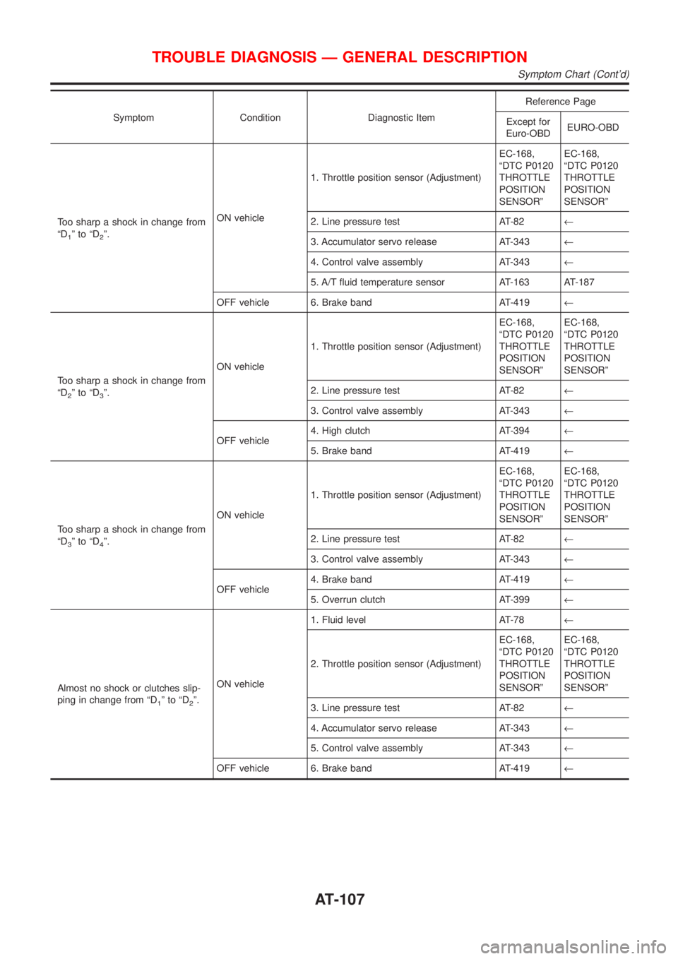
Symptom Condition Diagnostic ItemReference Page
Except for
Euro-OBDEURO-OBD
Too sharp a shock in change from
ªD
1ºtoªD2º.ON vehicle1. Throttle position sensor (Adjustment)EC-168,
ªDTC P0120
THROTTLE
POSITION
SENSORºEC-168,
ªDTC P0120
THROTTLE
POSITION
SENSORº
2. Line pressure test AT-82¬
3. Accumulator servo release AT-343¬
4. Control valve assembly AT-343¬
5. A/T fluid temperature sensor AT-163 AT-187
OFF vehicle 6. Brake band AT-419¬
Too sharp a shock in change from
ªD
2ºtoªD3º.ON vehicle1. Throttle position sensor (Adjustment)EC-168,
ªDTC P0120
THROTTLE
POSITION
SENSORºEC-168,
ªDTC P0120
THROTTLE
POSITION
SENSORº
2. Line pressure test AT-82¬
3. Control valve assembly AT-343¬
OFF vehicle4. High clutch AT-394¬
5. Brake band AT-419¬
Too sharp a shock in change from
ªD
3ºtoªD4º.ON vehicle1. Throttle position sensor (Adjustment)EC-168,
ªDTC P0120
THROTTLE
POSITION
SENSORºEC-168,
ªDTC P0120
THROTTLE
POSITION
SENSORº
2. Line pressure test AT-82¬
3. Control valve assembly AT-343¬
OFF vehicle4. Brake band AT-419¬
5. Overrun clutch AT-399¬
Almost no shock or clutches slip-
ping in change from ªD
1ºtoªD2º.ON vehicle1. Fluid level AT-78¬
2. Throttle position sensor (Adjustment)EC-168,
ªDTC P0120
THROTTLE
POSITION
SENSORºEC-168,
ªDTC P0120
THROTTLE
POSITION
SENSORº
3. Line pressure test AT-82¬
4. Accumulator servo release AT-343¬
5. Control valve assembly AT-343¬
OFF vehicle 6. Brake band AT-419¬
TROUBLE DIAGNOSIS Ð GENERAL DESCRIPTION
Symptom Chart (Cont'd)
AT-107