EL page 71 NISSAN ALMERA N16 2001 Electronic Workshop Manual
[x] Cancel search | Manufacturer: NISSAN, Model Year: 2001, Model line: ALMERA N16, Model: NISSAN ALMERA N16 2001Pages: 2493, PDF Size: 66.97 MB
Page 843 of 2493
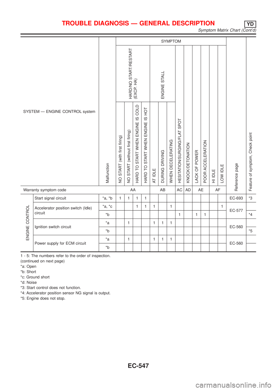
SYSTEM Ð ENGINE CONTROL system
Malfunction
SYMPTOM
Reference page
Feature of symptom, Check pointHARD/NO START/RESTART
(EXCP. HA)
ENGINE STALL
HESITATION/SURGING/FLAT SPOT
KNOCK/DETONATION
LACK OF POWER
POOR ACCELERATION
HI IDLE
LOW IDLE NO START (with first firing)
NO START (without first firing)
HARD TO START WHEN ENGINE IS COLD
HARD TO START WHEN ENGINE IS HOT
AT IDLE
DURING DRIVING
WHEN DECELERATINGWarranty symptom code AA AB AC AD AE AF
ENGINE CONTROL
Start signal circuit *a, *b1111EC-693 *3
Accelerator position switch (Idle)
circuit*a, *c 1 1 1 1 1
EC-577
*b 1 1 1 *4
Ignition switch circuit*a 1 111
EC-560
*b*5
Power supply for ECM circuit*a 1 111
EC-560
*b
1 - 5: The numbers refer to the order of inspection.
(continued on next page)
*a: Open
*b: Short
*c: Ground short
*d: Noise
*3: Start control does not function.
*4: Accelerator position sensor NG signal is output.
*5: Engine does not stop.
TROUBLE DIAGNOSIS Ð GENERAL DESCRIPTIONYD
Symptom Matrix Chart (Cont'd)
EC-547
Page 844 of 2493
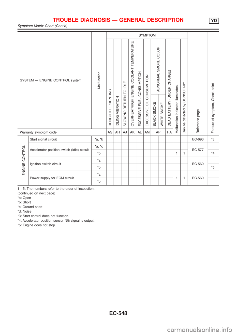
SYSTEM Ð ENGINE CONTROL system
Malfunction
SYMPTOM
Reference page
Feature of symptom, Check pointROUGH IDLE/HUNTING
IDLING VIBRATION
SLOW/NO RETURN TO IDLE
OVERHEAT/HIGH ENGINE COOLANT TEMPERATURE
EXCESSIVE FUEL CONSUMPTION
EXCESSIVE OIL CONSUMPTION
ABNORMAL SMOKE COLOR
DEAD BATTERY (UNDER CHARGE)
Malfunction indicator illuminates.
Can be detected by CONSULT-II?BLACK SMOKE
WHITE SMOKEWarranty symptom code AG AH AJ AK AL AM AP HA
ENGINE CONTROL
Start signal circuit *a, *b EC-693 *3
Accelerator position switch (Idle) circuit*a, *c
EC-577
*b 1 1 *4
Ignition switch circuit*a
EC-560
*b*5
Power supply for ECM circuit*a
1 1 EC-560
*b
1 - 5: The numbers refer to the order of inspection.
(continued on next page)
*a: Open
*b: Short
*c: Ground short
*d: Noise
*3: Start control does not function.
*4: Accelerator position sensor NG signal is output.
*5: Engine does not stop.
TROUBLE DIAGNOSIS Ð GENERAL DESCRIPTIONYD
Symptom Matrix Chart (Cont'd)
EC-548
Page 845 of 2493
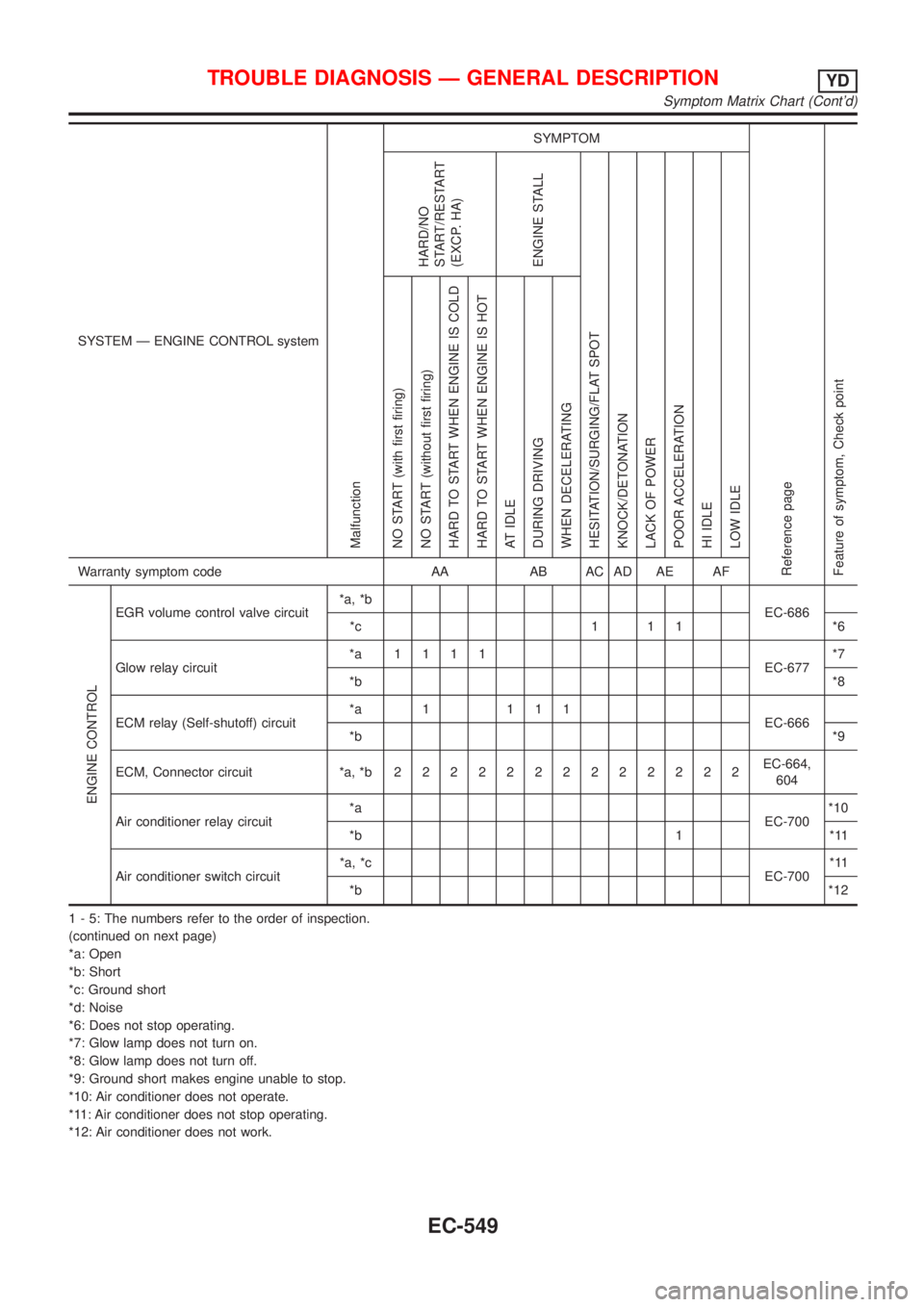
SYSTEM Ð ENGINE CONTROL system
Malfunction
SYMPTOM
Reference page
Feature of symptom, Check pointHARD/NO
START/RESTART
(EXCP. HA)
ENGINE STALL
HESITATION/SURGING/FLAT SPOT
KNOCK/DETONATION
LACK OF POWER
POOR ACCELERATION
HI IDLE
LOW IDLE NO START (with first firing)
NO START (without first firing)
HARD TO START WHEN ENGINE IS COLD
HARD TO START WHEN ENGINE IS HOT
AT IDLE
DURING DRIVING
WHEN DECELERATINGWarranty symptom code AA AB AC AD AE AF
ENGINE CONTROL
EGR volume control valve circuit*a, *b
EC-686
*c 1 1 1 *6
Glow relay circuit*a 1111
EC-677*7
*b*8
ECM relay (Self-shutoff) circuit*a 1 111
EC-666
*b*9
ECM, Connector circuit *a, *b2222222222222EC-664,
604
Air conditioner relay circuit*a
EC-700*10
*b 1 *11
Air conditioner switch circuit*a, *c
EC-700*11
*b*12
1 - 5: The numbers refer to the order of inspection.
(continued on next page)
*a: Open
*b: Short
*c: Ground short
*d: Noise
*6: Does not stop operating.
*7: Glow lamp does not turn on.
*8: Glow lamp does not turn off.
*9: Ground short makes engine unable to stop.
*10: Air conditioner does not operate.
*11: Air conditioner does not stop operating.
*12: Air conditioner does not work.
TROUBLE DIAGNOSIS Ð GENERAL DESCRIPTIONYD
Symptom Matrix Chart (Cont'd)
EC-549
Page 846 of 2493
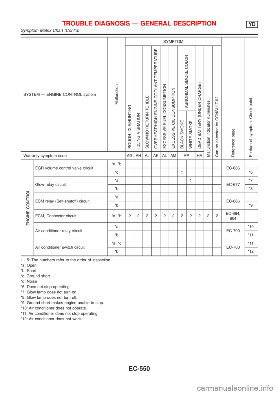
SYSTEM Ð ENGINE CONTROL system
Malfunction
SYMPTOM
Reference page
Feature of symptom, Check pointROUGH IDLE/HUNTING
IDLING VIBRATION
SLOW/NO RETURN TO IDLE
OVERHEAT/HIGH ENGINE COOLANT TEMPERATURE
EXCESSIVE FUEL CONSUMPTION
EXCESSIVE OIL CONSUMPTION
ABNORMAL SMOKE COLOR
DEAD BATTERY (UNDER CHARGE)
Malfunction indicator illuminates.
Can be detected by CONSULT-II?BLACK SMOKE
WHITE SMOKEWarranty symptom code AG AH AJ AK AL AM AP HA
ENGINE CONTROL
EGR volume control valve circuit*a, *b
EC-686
*c 1 *6
Glow relay circuit*a 1
EC-677*7
*b*8
ECM relay (Self-shutoff) circuit*a
EC-666
*b*9
ECM, Connector circuit *a, *b22222222222EC-664,
604
Air conditioner relay circuit*a
EC-700*10
*b*11
Air conditioner switch circuit*a, *c
EC-700*11
*b*12
1 - 5: The numbers refer to the order of inspection.
*a: Open
*b: Short
*c: Ground short
*d: Noise
*6: Does not stop operating.
*7: Glow lamp does not turn on.
*8: Glow lamp does not turn off.
*9: Ground short makes engine unable to stop.
*10: Air conditioner does not operate.
*11: Air conditioner does not stop operating.
*12: Air conditioner does not work.
TROUBLE DIAGNOSIS Ð GENERAL DESCRIPTIONYD
Symptom Matrix Chart (Cont'd)
EC-550
Page 929 of 2493
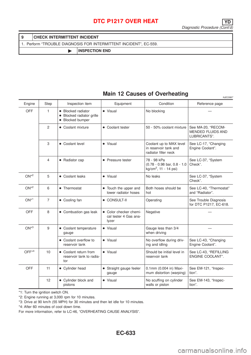
9 CHECK INTERMITTENT INCIDENT
1. Perform ªTROUBLE DIAGNOSIS FOR INTERMITTENT INCIDENTº, EC-559.
©INSPECTION END
Main 12 Causes of OverheatingNJEC0667
Engine Step Inspection item Equipment Condition Reference page
OFF 1+Blocked radiator
+Blocked radiator grille
+Blocked bumper+Visual No blocking Ð
2+Coolant mixture+Coolant tester 50 - 50% coolant mixture See MA-20, ªRECOM-
MENDED FLUIDS AND
LUBRICANTSº.
3+Coolant level+Visual Coolant up to MAX level
in reservoir tank and
radiator filler neckSee LC-17, ªChanging
Engine Coolantº.
4+Radiator cap+Pressure tester 78 - 98 kPa
(0.78 - 0.98 bar, 0.8 - 1.0
kg/cm
2, 11 - 14 psi)See LC-37, ªSystem
Checkº.
ON*
25+Coolant leaks+Visual No leaks See LC-37, ªSystem
Checkº.
ON*
26+Thermostat+Touch the upper and
lower radiator hosesBoth hoses should be
hotSee LC-40, ªThermostatº
and ªRadiatorº.
ON*
17+Cooling fan+CONSULT-II Operating See Trouble Diagnosis
for DTC P1217, EC-618.
OFF 8+Combustion gas leak+Color checker chemi-
cal tester 4 Gas ana-
lyzerNegative Ð
ON*
39+Coolant temperature
gauge+Visual Gauge less than 3/4
when drivingÐ
+Coolant overflow to
reservoir tank+Visual No overflow during driv-
ing and idlingSee LC-43, ªChanging
Engine Coolantº.
OFF*
410+Coolant return from
reservoir tank to radia-
tor+Visual Should be initial level in
reservoir tankSee LC-43, ªREFILLING
ENGINE COOLANTº.
OFF 11+Cylinder head+Straight gauge feeler
gauge0.1mm (0.004 in) Maxi-
mum distortion (warping)See EM-121, ªInspec-
tionº.
12+Cylinder block and
pistons+Visual No scuffing on cylinder
walls or pistonSee EM-143, ªInspec-
tionº.
*1: Turn the ignition switch ON.
*2: Engine running at 3,000 rpm for 10 minutes.
*3: Drive at 90 km/h (55 MPH) for 30 minutes and then let idle for 10 minutes.
*4: After 60 minutes of cool down time.
For more information, refer to LC-46, ªOVERHEATING CAUSE ANALYSISº.
DTC P1217 OVER HEATYD
Diagnostic Procedure (Cont'd)
EC-633
Page 1030 of 2493
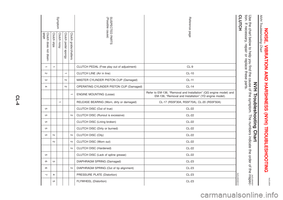
NJCL0004
NVH Troubleshooting ChartNJCL0004S01Use the chart below to help you find the cause of the symptom. The numbers indicate the order of the inspec-
tion. If necessary, repair or replace these parts.
CLUTCHNJCL0004S0101
Reference pageCL-9
CL-10
CL-11
CL-14
Refer to EM-136, ªRemoval and Installationº (QG engine model) and
EM-136, ªRemoval and Installationº (YD engine model).
CL-17 (RS5F30A, RS5F70A), CL-20 (RS5F50A)
CL-22
CL-22
CL-22
CL-22
CL-22
CL-22
CL-22
CL-22
CL-23
CL-23
CL-23
CL-23
SUSPECTED PARTS
(Possible cause)
CLUTCH PEDAL (Free play out of adjustment)
CLUTCH LINE (Air in line)
MASTER CYLINDER PISTON CUP (Damaged)
OPERATING CYLINDER PISTON CUP (Damaged)
ENGINE MOUNTING (Loose)
RELEASE BEARING (Worn, dirty or damaged)
CLUTCH DISC (Out of true)
CLUTCH DISC (Runout is excessive)
CLUTCH DISC (Lining broken)
CLUTCH DISC (Dirty or burned)
CLUTCH DISC (Oily)
CLUTCH DISC (Worn out)
CLUTCH DISC (Hardened)
CLUTCH DISC (Lack of spline grease)
DIAPHRAGM SPRING (Damaged)
DIAPHRAGM SPRING (Out of tip alignment)
PRESSURE PLATE (Distortion)
FLYWHEEL (Distortion)
SymptomClutch grabs/chatters 1 2 2 2 2 2
Clutch pedal spongy 1 2 2
Clutch noisy 1
Clutch slips 1 2 2 3 4 5
Clutch does not disen-
gage1234 55555 5667
NOISE, VIBRATION AND HARSHNESS (NVH) TROUBLESHOOTING
NVH Troubleshooting Chart
CL-4
Page 1063 of 2493
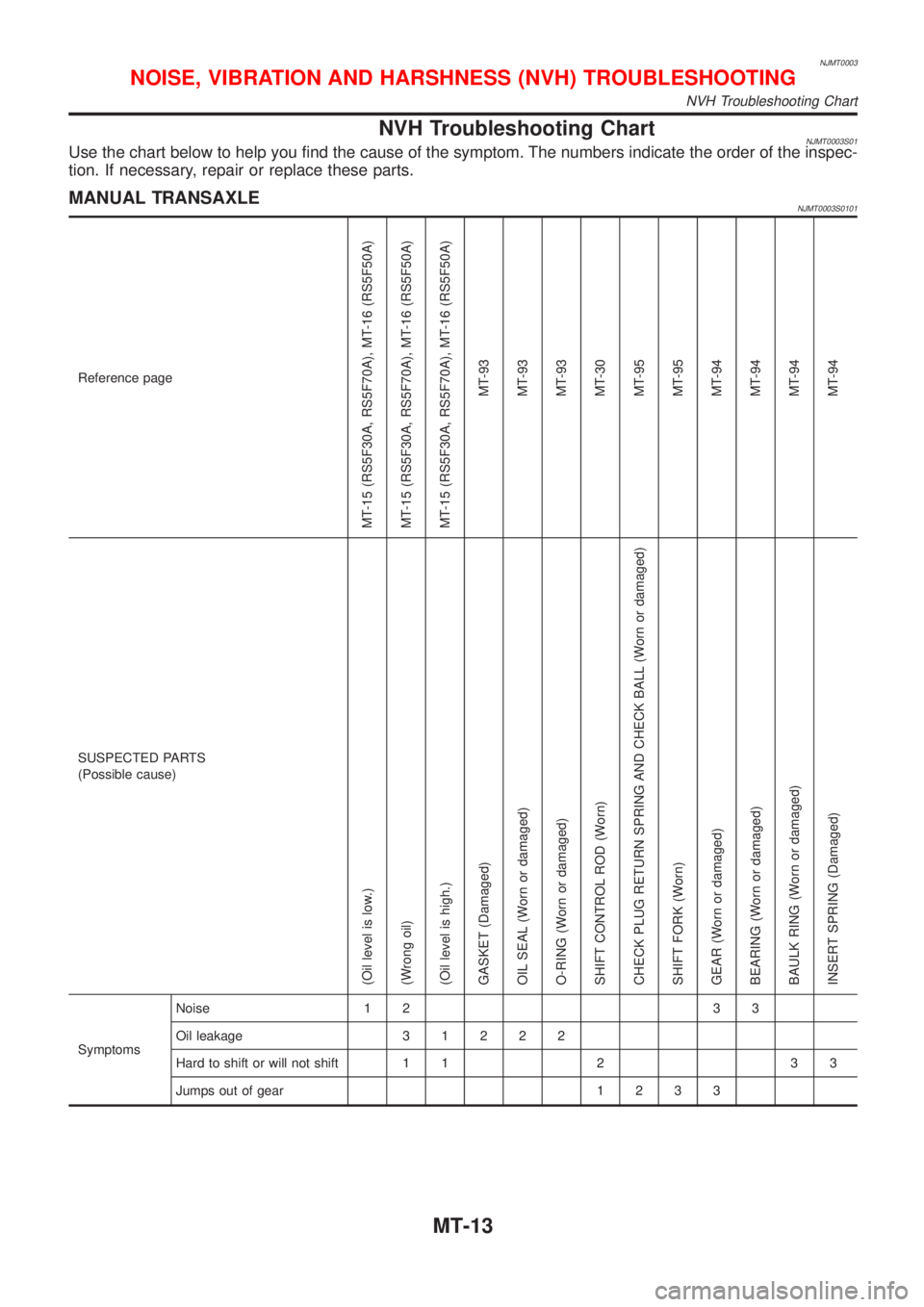
NJMT0003
NVH Troubleshooting ChartNJMT0003S01Use the chart below to help you find the cause of the symptom. The numbers indicate the order of the inspec-
tion. If necessary, repair or replace these parts.
MANUAL TRANSAXLENJMT0003S0101
Reference page
MT-15 (RS5F30A, RS5F70A), MT-16 (RS5F50A)
MT-15 (RS5F30A, RS5F70A), MT-16 (RS5F50A)
MT-15 (RS5F30A, RS5F70A), MT-16 (RS5F50A)
MT-93
MT-93
MT-93
MT-30
MT-95
MT-95
MT-94
MT-94
MT-94
MT-94
SUSPECTED PARTS
(Possible cause)
(Oil level is low.)
(Wrong oil)
(Oil level is high.)
GASKET (Damaged)
OIL SEAL (Worn or damaged)
O-RING (Worn or damaged)
SHIFT CONTROL ROD (Worn)
CHECK PLUG RETURN SPRING AND CHECK BALL (Worn or damaged)
SHIFT FORK (Worn)
GEAR (Worn or damaged)
BEARING (Worn or damaged)
BAULK RING (Worn or damaged)
INSERT SPRING (Damaged)
SymptomsNoise 1 2 3 3
Oil leakage31222
Hard to shift or will not shift 1 1 2 3 3
Jumps out of gear1233
NOISE, VIBRATION AND HARSHNESS (NVH) TROUBLESHOOTING
NVH Troubleshooting Chart
MT-13
Page 1191 of 2493
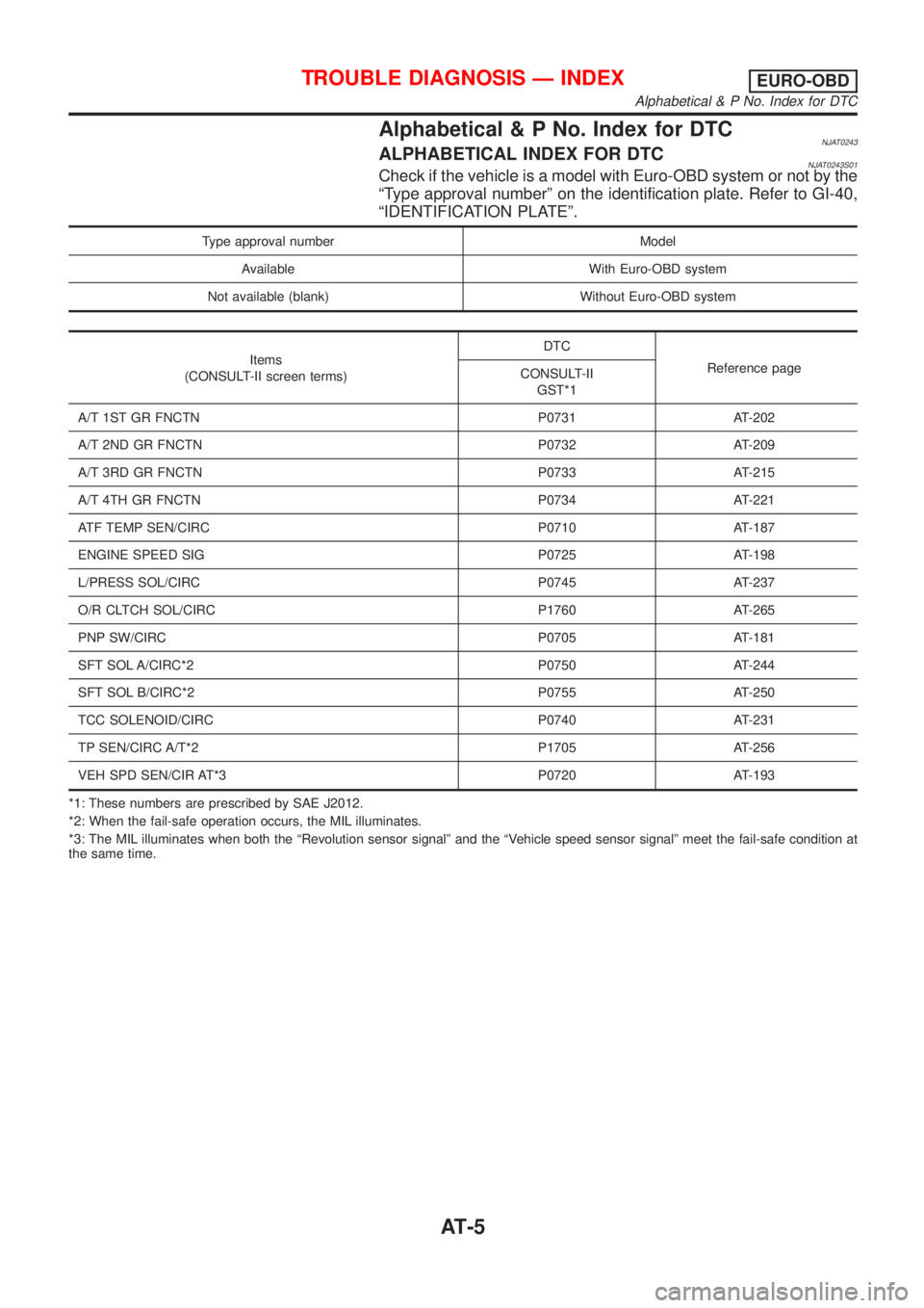
Alphabetical & P No. Index for DTCNJAT0243ALPHABETICAL INDEX FOR DTCNJAT0243S01Check if the vehicle is a model with Euro-OBD system or not by the
ªType approval numberº on the identification plate. Refer to GI-40,
ªIDENTIFICATION PLATEº.
Type approval number Model
Available With Euro-OBD system
Not available (blank) Without Euro-OBD system
Items
(CONSULT-II screen terms)DTC
Reference page
CONSULT-II
GST*1
A/T 1ST GR FNCTN P0731 AT-202
A/T 2ND GR FNCTN P0732 AT-209
A/T 3RD GR FNCTN P0733 AT-215
A/T 4TH GR FNCTN P0734 AT-221
ATF TEMP SEN/CIRC P0710 AT-187
ENGINE SPEED SIG P0725 AT-198
L/PRESS SOL/CIRC P0745 AT-237
O/R CLTCH SOL/CIRC P1760 AT-265
PNP SW/CIRC P0705 AT-181
SFT SOL A/CIRC*2 P0750 AT-244
SFT SOL B/CIRC*2 P0755 AT-250
TCC SOLENOID/CIRC P0740 AT-231
TP SEN/CIRC A/T*2 P1705 AT-256
VEH SPD SEN/CIR AT*3 P0720 AT-193
*1: These numbers are prescribed by SAE J2012.
*2: When the fail-safe operation occurs, the MIL illuminates.
*3: The MIL illuminates when both the ªRevolution sensor signalº and the ªVehicle speed sensor signalº meet the fail-safe condition at
the same time.
TROUBLE DIAGNOSIS Ð INDEXEURO-OBD
Alphabetical & P No. Index for DTC
AT-5
Page 1192 of 2493
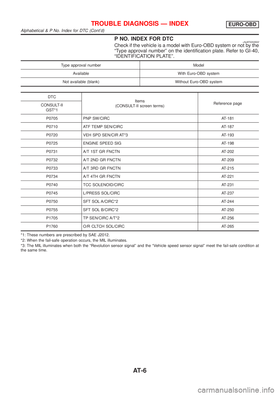
P NO. INDEX FOR DTC=NJAT0243S02Check if the vehicle is a model with Euro-OBD system or not by the
ªType approval numberº on the identification plate. Refer to GI-40,
ªIDENTIFICATION PLATEº.
Type approval number Model
Available With Euro-OBD system
Not available (blank) Without Euro-OBD system
DTC
Items
(CONSULT-II screen terms)Reference page
CONSULT-II
GST*1
P0705 PNP SW/CIRC AT-181
P0710 ATF TEMP SEN/CIRC AT-187
P0720 VEH SPD SEN/CIR AT*3 AT-193
P0725 ENGINE SPEED SIG AT-198
P0731 A/T 1ST GR FNCTN AT-202
P0732 A/T 2ND GR FNCTN AT-209
P0733 A/T 3RD GR FNCTN AT-215
P0734 A/T 4TH GR FNCTN AT-221
P0740 TCC SOLENOID/CIRC AT-231
P0745 L/PRESS SOL/CIRC AT-237
P0750 SFT SOL A/CIRC*2 AT-244
P0755 SFT SOL B/CIRC*2 AT-250
P1705 TP SEN/CIRC A/T*2 AT-256
P1760 O/R CLTCH SOL/CIRC AT-265
*1: These numbers are prescribed by SAE J2012.
*2: When the fail-safe operation occurs, the MIL illuminates.
*3: The MIL illuminates when both the ªRevolution sensor signalº and the ªVehicle speed sensor signalº meet the fail-safe condition at
the same time.
TROUBLE DIAGNOSIS Ð INDEXEURO-OBD
Alphabetical & P No. Index for DTC (Cont'd)
AT-6
Page 1194 of 2493
AAT470A
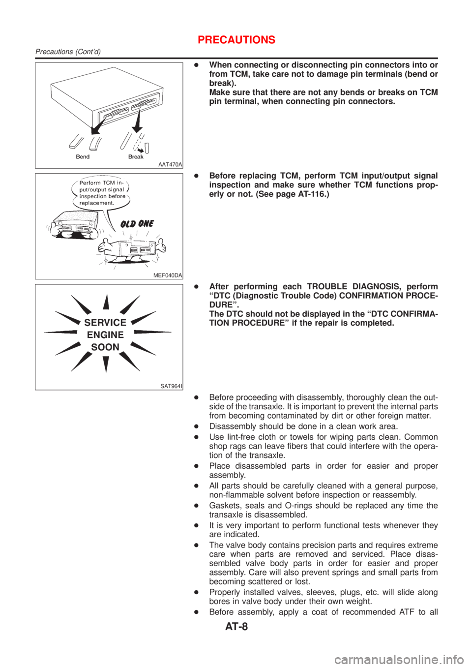
+When connecting or disconnecting pin connectors into or
from TCM, take care not to damage pin terminals (bend or
break).
Make sure that there are not any bends or breaks on TCM
pin terminal, when connecting pin connectors.
MEF040DA
+Before replacing TCM, perform TCM input/output signal
inspection and make sure whether TCM functions prop-
erly or not. (See page AT-116.)
SAT964I
+After performing each TROUBLE DIAGNOSIS, perform
ªDTC (Diagnostic Trouble Code) CONFIRMATION PROCE-
DUREº.
The DTC should not be displayed in the ªDTC CONFIRMA-
TION PROCEDUREº if the repair is completed.
+Before proceeding with disassembly, thoroughly clean the out-
side of the transaxle. It is important to prevent the internal parts
from becoming contaminated by dirt or other foreign matter.
+Disassembly should be done in a clean work area.
+Use lint-free cloth or towels for wiping parts clean. Common
shop rags can leave fibers that could interfere with the opera-
tion of the transaxle.
+Place disassembled parts in order for easier and proper
assembly.
+All parts should be carefully cleaned with a general purpose,
non-flammable solvent before inspection or reassembly.
+Gaskets, seals and O-rings should be replaced any time the
transaxle is disassembled.
+It is very important to perform functional tests whenever they
are indicated.
+The valve body contains precision parts and requires extreme
care when parts are removed and serviced. Place disas-
sembled valve body parts in order for easier and proper
assembly. Care will also prevent springs and small parts from
becoming scattered or lost.
+Properly installed valves, sleeves, plugs, etc. will slide along
bores in valve body under their own weight.
+Before assembly, apply a coat of recommended ATF to all
PRECAUTIONS
Precautions (Cont'd)
AT-8