engine coolant NISSAN ALMERA N16 2003 Electronic Repair Manual
[x] Cancel search | Manufacturer: NISSAN, Model Year: 2003, Model line: ALMERA N16, Model: NISSAN ALMERA N16 2003Pages: 3189, PDF Size: 54.76 MB
Page 1198 of 3189
9 CHECK INTERMITTENT INCIDENT
1. Perform “TROUBLE DIAGNOSIS FOR INTERMITTENT INCIDENT”, EC-71.
INSPECTION END
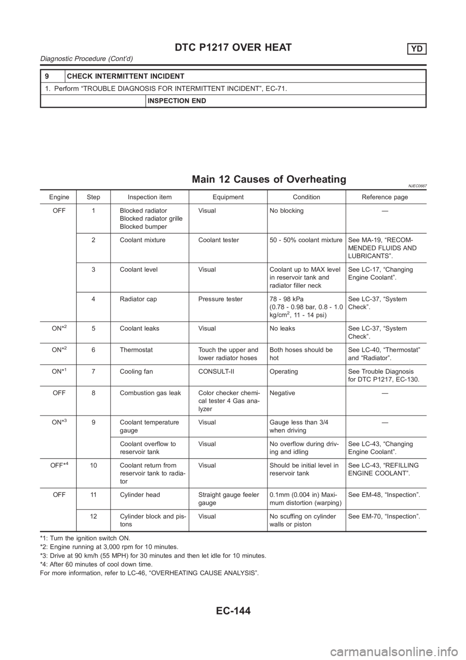
Main 12 Causes of OverheatingNJEC0667
Engine Step Inspection item Equipment Condition Reference page
OFF 1 Blocked radiator
Blocked radiator grille
Blocked bumperVisual No blocking —
2 Coolant mixture Coolant tester 50 - 50% coolant mixture See MA-19, “RECOM-
MENDED FLUIDS AND
LUBRICANTS”.
3 Coolant level Visual Coolant up to MAX level
in reservoir tank and
radiator filler neckSee LC-17, “Changing
Engine Coolant”.
4 Radiator cap Pressure tester 78 - 98 kPa
(0.78 - 0.98 bar, 0.8 - 1.0
kg/cm
2, 11 - 14 psi)See LC-37, “System
Check”.
ON*
25 Coolant leaks Visual No leaks See LC-37, “System
Check”.
ON*
26 Thermostat Touch the upper and
lower radiator hosesBoth hoses should be
hotSee LC-40, “Thermostat”
and “Radiator”.
ON*
17 Cooling fan CONSULT-II Operating See Trouble Diagnosis
for DTC P1217, EC-130.
OFF 8 Combustion gas leak Color checker chemi-
cal tester 4 Gas ana-
lyzerNegative —
ON*
39 Coolant temperature
gaugeVisual Gauge less than 3/4
when driving—
Coolant overflow to
reservoir tankVisual No overflow during driv-
ing and idlingSee LC-43, “Changing
Engine Coolant”.
OFF*
410 Coolant return from
reservoir tank to radia-
torVisual Should be initial level in
reservoir tankSee LC-43, “REFILLING
ENGINE COOLANT”.
OFF 11 Cylinder head Straight gauge feeler
gauge0.1mm (0.004 in) Maxi-
mum distortion (warping)See EM-48, “Inspection”.
12 Cylinder block and pis-
tonsVisual No scuffing on cylinder
walls or pistonSee EM-70, “Inspection”.
*1: Turn the ignition switch ON.
*2: Engine running at 3,000 rpm for 10 minutes.
*3: Drive at 90 km/h (55 MPH) for 30 minutes and then let idle for 10 minutes.
*4: After 60 minutes of cool down time.
For more information, refer to LC-46, “OVERHEATING CAUSE ANALYSIS”.
DTC P1217 OVER HEATYD
Diagnostic Procedure (Cont’d)
EC-144
Page 1242 of 3189
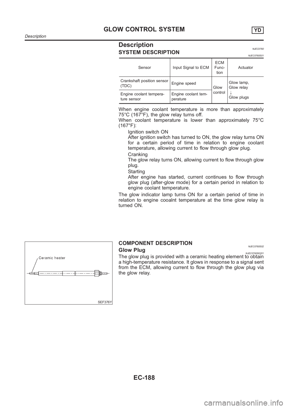
DescriptionNJEC0760SYSTEM DESCRIPTIONNJEC0760S01
Sensor Input Signal to ECMECM
Func-
tionActuator
Crankshaft position sensor
(TDC)Engine speed
Glow
controlGlow lamp,
Glow relay
"
Glow plugs Engine coolant tempera-
ture sensorEngine coolant tem-
perature
When engine coolant temperature is more than approximately
75°C (167°F), the glow relay turns off.
When coolant temperature is lower than approximately 75°C
(167°F):
Ignition switch ON
After ignition switch has turned to ON, the glow relay turns ON
for a certain period of time in relation to engine coolant
temperature, allowing current to flow through glow plug.
Cranking
The glow relay turns ON, allowing current to flow through glow
plug.
Starting
After engine has started, current continues to flow through
glow plug (after-glow mode) for a certain period in relation to
engine coolant temperature.
The glow indicator lamp turns ON for a certain period of time in
relation to engine cooalnt temperature at the time glow relay is
turned ON.
SEF376Y
COMPONENT DESCRIPTIONNJEC0760S02Glow PlugNJEC0760S0201The glow plug is provided with a ceramic heating element to obtain
a high-temperature resistance. It glows in response to a signal sent
from the ECM, allowing current to flow through the glow plug via
the glow relay.
GLOW CONTROL SYSTEMYD
Description
EC-188
Page 1246 of 3189
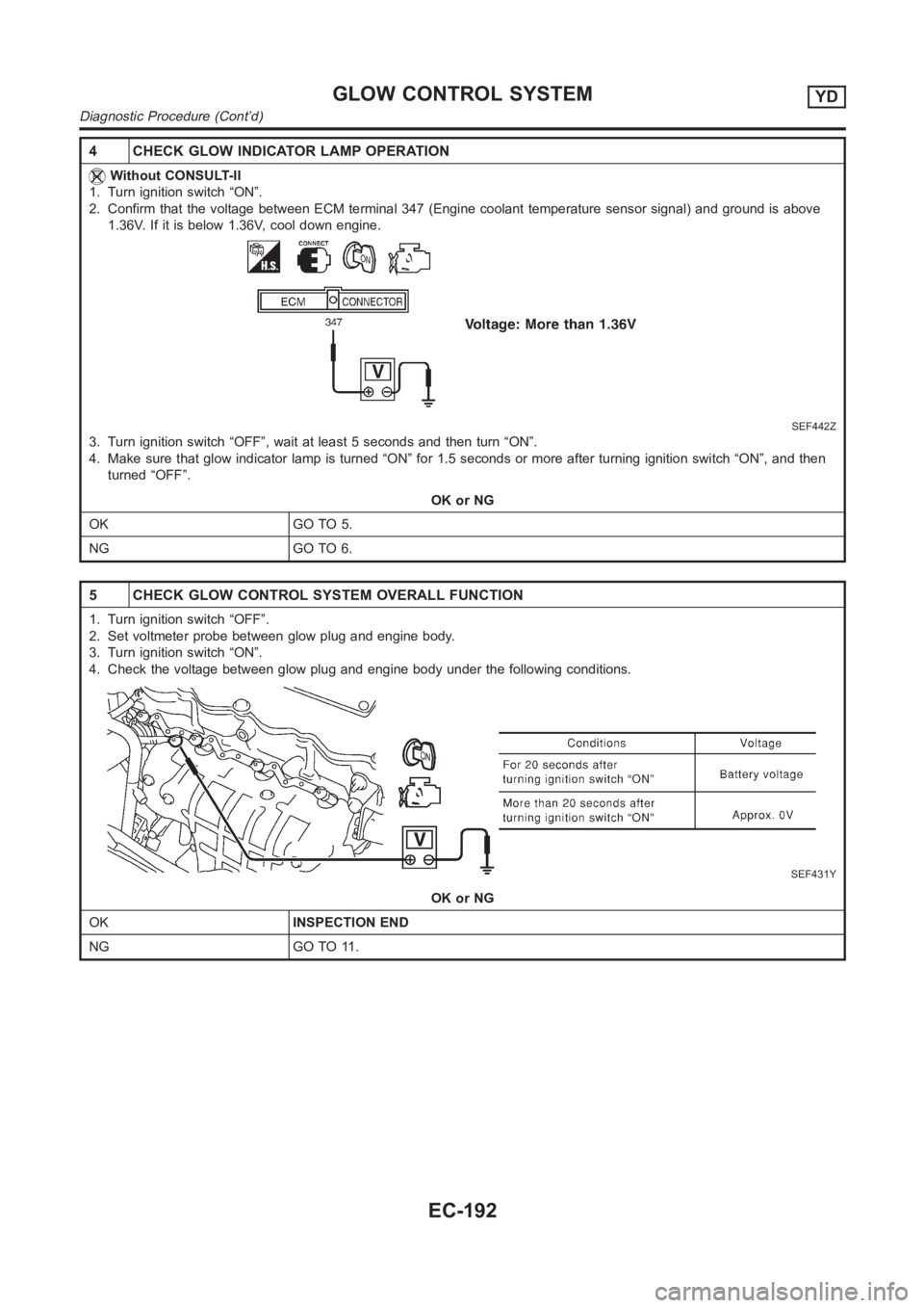
4 CHECK GLOW INDICATOR LAMP OPERATION
Without CONSULT-II
1. Turn ignition switch “ON”.
2. Confirm that the voltage between ECM terminal 347 (Engine coolant temperature sensor signal) and ground is above
1.36V. If it is below 1.36V, cool down engine.
SEF442Z
3. Turn ignition switch “OFF”, wait at least 5 seconds and then turn “ON”.
4. Make sure that glow indicator lamp is turned “ON” for 1.5 seconds or more after turning ignition switch “ON”, and then
turned “OFF”.
OK or NG
OK GO TO 5.
NG GO TO 6.
5 CHECK GLOW CONTROL SYSTEM OVERALL FUNCTION
1. Turn ignition switch “OFF”.
2. Set voltmeter probe between glow plug and engine body.
3. Turn ignition switch “ON”.
4. Check the voltage between glow plug and engine body under the following conditions.
SEF431Y
OK or NG
OKINSPECTION END
NG GO TO 11.
GLOW CONTROL SYSTEMYD
Diagnostic Procedure (Cont’d)
EC-192
Page 1251 of 3189
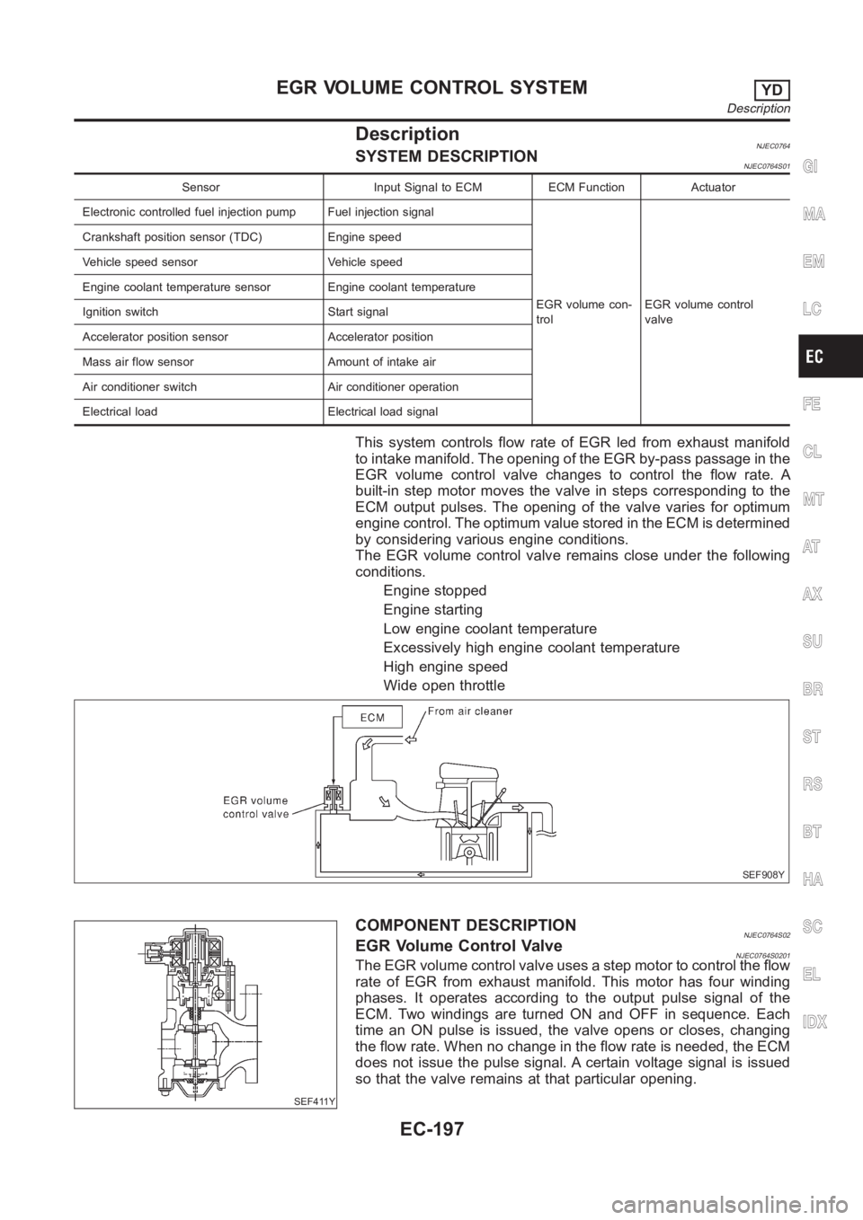
DescriptionNJEC0764SYSTEM DESCRIPTIONNJEC0764S01
Sensor Input Signal to ECM ECM Function Actuator
Electronic controlled fuel injection pump Fuel injection signal
EGR volume con-
trolEGR volume control
valve Crankshaft position sensor (TDC) Engine speed
Vehicle speed sensor Vehicle speed
Engine coolant temperature sensor Engine coolant temperature
Ignition switch Start signal
Accelerator position sensor Accelerator position
Mass air flow sensor Amount of intake air
Air conditioner switch Air conditioner operation
Electrical load Electrical load signal
This system controls flow rate of EGR led from exhaust manifold
to intake manifold. The opening of the EGR by-pass passage in the
EGR volume control valve changes to control the flow rate. A
built-in step motor moves the valve in steps corresponding to the
ECM output pulses. The opening of the valve varies for optimum
engine control. The optimum value stored in the ECM is determined
by considering various engine conditions.
The EGR volume control valve remains close under the following
conditions.
Engine stopped
Engine starting
Low engine coolant temperature
Excessively high engine coolant temperature
High engine speed
Wide open throttle
SEF908Y
SEF411Y
COMPONENT DESCRIPTIONNJEC0764S02EGR Volume Control ValveNJEC0764S0201The EGR volume control valve uses a step motor to control the flow
rate of EGR from exhaust manifold. This motor has four winding
phases. It operates according to the output pulse signal of the
ECM. Two windings are turned ON and OFF in sequence. Each
time an ON pulse is issued, the valve opens or closes, changing
the flow rate. When no change in the flow rate is needed, the ECM
does not issue the pulse signal. A certain voltage signal is issued
so that the valve remains at that particular opening.
GI
MA
EM
LC
FE
CL
MT
AT
AX
SU
BR
ST
RS
BT
HA
SC
EL
IDX
EGR VOLUME CONTROL SYSTEMYD
Description
EC-197
Page 1268 of 3189
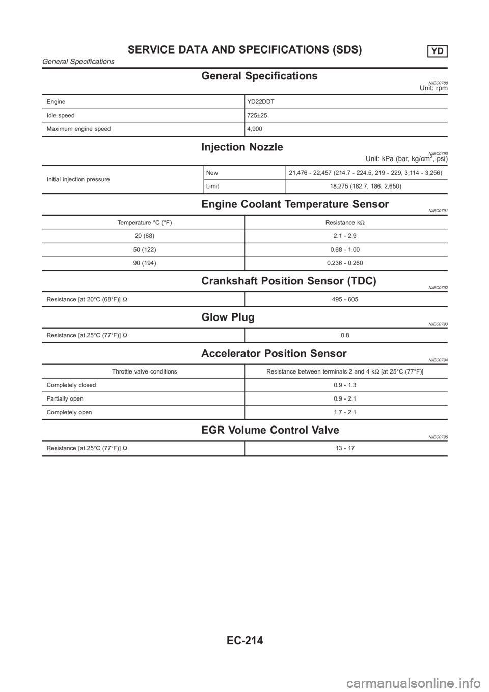
General SpecificationsNJEC0788Unit: rpm
Engine YD22DDT
Idle speed 725±25
Maximum engine speed 4,900
Injection NozzleNJEC0790Unit: kPa (bar, kg/cm2, psi)
Initial injection pressureNew 21,476 - 22,457 (214.7 - 224.5, 219 - 229, 3,114 - 3,256)
Limit 18,275 (182.7, 186, 2,650)
Engine Coolant Temperature SensorNJEC0791
Temperature °C (°F) Resistance kΩ
20 (68) 2.1 - 2.9
50 (122) 0.68 - 1.00
90 (194) 0.236 - 0.260
Crankshaft Position Sensor (TDC)NJEC0792
Resistance [at 20°C (68°F)]Ω495 - 605
Glow PlugNJEC0793
Resistance [at 25°C (77°F)]Ω0.8
Accelerator Position SensorNJEC0794
Throttle valve conditions Resistance between terminals 2 and 4 kΩ[at 25°C (77°F)]
Completely closed0.9 - 1.3
Partially open0.9 - 2.1
Completely open1.7 - 2.1
EGR Volume Control ValveNJEC0795
Resistance [at 25°C (77°F)]Ω13 - 17
SERVICE DATA AND SPECIFICATIONS (SDS)YD
General Specifications
EC-214
Page 1463 of 3189
PRECAUTIONS
AT-7
D
E
F
G
H
I
J
K
L
MA
B
AT
●After performing each TROUBLE DIAGNOSIS, perform
“DTC (Diagnostic Trouble Code) CONFIRMATION PROCE-
DURE”.
The DTC should not be displayed in the “DTC CONFIRMA-
TION PROCEDURE” if the repair is completed.
●Before proceeding with disassembly, thoroughly clean the out-
side of the transaxle. It is important to prevent the internal parts
from becoming contaminated by dirt or other foreign matter.
●Disassembly should be done in a clean work area.
●Use lint-free cloth or towels for wiping parts clean. Common
shop rags can leave fibers that could interfere with the operation
of the transaxle.
●Place disassembled parts in order for easier and proper assembly.
●All parts should be carefully cleaned with a general purpose, non-flammable solvent before inspection or
reassembly.
●Gaskets, seals and O-rings should be replaced any time the transaxle is disassembled.
●It is very important to perform functional tests whenever they are indicated.
●The valve body contains precision parts and requires extreme care when parts are removed and serviced.
Place disassembled valve body parts in order for easier and proper assembly. Care will also prevent
springs and small parts from becoming scattered or lost.
●Properly installed valves, sleeves, plugs, etc. will slide along bores in valve body under their own weight.
●Before assembly, apply a coat of recommended ATF to all parts. Apply petroleum jelly to protect O-rings
and seals, or hold bearings and washers in place during assembly. Do not use grease.
●Extreme care should be taken to avoid damage to O-rings, seals and gaskets when assembling.
●After overhaul, refill the transaxle with new ATF.
●When the A/T drain plug is removed, only some of the fluid is drained. Old A/T fluid will remain in torque
converter and ATF cooling system.
Always follow the procedures under AT-13, "
Changing A/T Fluid" when changing A/T fluid.
Service Notice or PrecautionsECS007N8
FA I L - S A F E
The TCM has an electronic Fail-Safe (limp home mode). This allows the vehicle to be driven even if a major
electrical input/output device circuit is damaged.
Under Fail-Safe, the vehicle always runs in third gear, even with a shift lever position of “1”, “2” or “D”. The cus-
tomer may complain of sluggish or poor acceleration.
When the ignition key is turned “ON” following Fail-Safe operation, O/D OFF indicator lamp blinks for about 8
seconds. Refer to AT- 2 5 0 , "
Diagnostic Procedure Without CONSULT-II" (EXCEPT FOR EURO-OBD) or AT-
51, "TCM SELF-DIAGNOSTIC PROCEDURE (NO TOOLS)" (EURO-OBD).
The blinking of the O/D OFF indicator lamp for about 8 seconds will appear only once and be cleared. The
customer may resume normal driving conditions.
Always follow the “Work Flow”, refer to AT- 2 5 9
(EXCEPT FOR EURO-OBD) or AT- 6 0 (EURO-OBD).
The SELF-DIAGNOSIS results will be as follows:
●The first SELF-DIAGNOSIS will indicate damage to the vehicle speed sensor or the revolution sensor.
●During the next SELF-DIAGNOSIS, performed after checking the sensor, no damages will be indicated.
TORQUE CONVERTER SERVICE
The torque converter should be replaced under any of the following conditions:
●External leaks in the hub weld area.
●Converter hub is scored or damaged.
●Converter pilot is broken, damaged or fits poorly into crankshaft.
●Steel particles are found after flushing the cooler and cooler lines.
●Pump is damaged or steel particles are found in the converter.
●Vehicle has TCC shudder and/or no TCC apply. Replace only after all hydraulic and electrical diagnoses
have been made. (Converter clutch material may be glazed.)
●Converter is contaminated with engine coolant containing antifreeze.
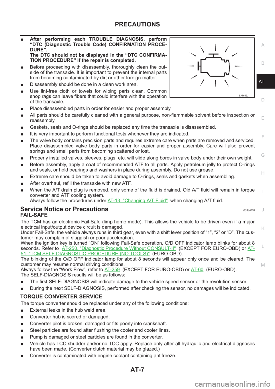
SAT652J
Page 1494 of 3189
![NISSAN ALMERA N16 2003 Electronic Repair Manual AT-38
[EURO-OBD]
ON BOARD DIAGNOSTIC SYSTEM DESCRIPTION
A sample of CONSULT-II display for DTC is shown in the following
page. DTC or 1st trip DTC of a malfunction is displayed i](/img/5/57350/w960_57350-1493.png "NISSAN ALMERA N16 2003 Electronic Repair Manual AT-38
[EURO-OBD]
ON BOARD DIAGNOSTIC SYSTEM DESCRIPTION
A sample of CONSULT-II display for DTC is shown in the following
page. DTC or 1st trip DTC of a malfunction is displayed i")
AT-38
[EURO-OBD]
ON BOARD DIAGNOSTIC SYSTEM DESCRIPTION
A sample of CONSULT-II display for DTC is shown in the following
page. DTC or 1st trip DTC of a malfunction is displayed in SELF
DIAGNOSIS mode for “ENGINE” with CONSULT-II. Time data indi-
cates how many times the vehicle was driven after the last detection
of a DTC.
If the DTC is being detected currently, the time data will be “0”.
If a 1st trip DTC is stored in the ECM, the time data will be “1t”.
Freeze Frame Data and 1st Trip Freeze Frame Data
The ECM has a memory function, which stores the driving condition such as fuel system status, calculated
load value, engine coolant temperature, short term fuel trim, long term fuel trim, engine speed and vehicle
speed at the moment the ECM detects a malfunction.
Data which are stored in the ECM memory, along with the 1st trip DTC, are called 1st trip freeze frame data,
and the data, stored together with the DTC data, are called freeze frame data and displayed on CONSULT-II
or GST. The 1st trip freeze frame data can only be displayed on the CONSULT-II screen, not on the GST. For
detail, refer to EC-87, "
CONSULT-II Function" (QG).
Only one set of freeze frame data (either 1st trip freeze frame data of freeze frame data) can be stored in the
ECM. 1st trip freeze frame data is stored in the ECM memory along with the 1st trip DTC. There is no priority
for 1st trip freeze frame data and it is updated each time a different 1st trip DTC is detected. However, once
freeze frame data (2nd trip detection/MI on) is stored in the ECM memory, 1st trip freeze frame data is no
longer stored. Remember, only one set of freeze frame data can be stored in the ECM.
The ECM has the following priorities to update the data.
Both 1st trip freeze frame data and freeze frame data (along with the DTCs) are cleared when the ECM mem-
ory is erased.
SAT014K
SAT015K
SAT016K
Priority Items
1 Freeze frame data Misfire — DTC: P0300 - P0306
Fuel Injection System Function — DTC: P0171, P0172, P0174, P0175
2 Except the above items (Includes A/T related items)
3 1st trip freeze frame data
Page 1565 of 3189
![NISSAN ALMERA N16 2003 Electronic Repair Manual CAN COMMUNICATION
AT-109
[EURO-OBD]
D
E
F
G
H
I
J
K
L
MA
B
AT
CAN COMMUNICATIONPFP:23710
System DescriptionECS007O2
CAN (Controller Area Network) is a serial communication line for real time applicati](/img/5/57350/w960_57350-1564.png "NISSAN ALMERA N16 2003 Electronic Repair Manual CAN COMMUNICATION
AT-109
[EURO-OBD]
D
E
F
G
H
I
J
K
L
MA
B
AT
CAN COMMUNICATIONPFP:23710
System DescriptionECS007O2
CAN (Controller Area Network) is a serial communication line for real time applicati")
CAN COMMUNICATION
AT-109
[EURO-OBD]
D
E
F
G
H
I
J
K
L
MA
B
AT
CAN COMMUNICATIONPFP:23710
System DescriptionECS007O2
CAN (Controller Area Network) is a serial communication line for real time application. It is an on-vehicle mul-
tiplex communication line with high data communication speed and excellent error detection ability. Many elec-
tronic control units are equipped onto a vehicle, and each control unit shares information and links with other
control units during operation (not independent). In CAN communication, control units are connected with 2
communication lines (CAN H line, CAN L line) allowing a high rate of information transmission with less wiring.
Each control unit transmits/receives data but selectively reads required data only.
CAN Communication UnitECS007O3
×:Applicable
TYPE1
System diagram
Input/output signal chart
T: Transmit R: Receive Body type Sedan/ 5DH/B/ 3DH/B
Axle2WD
Engine QG18DE QG15DE/QG18DE
Transmission A/T M/T
Brake controlABS
CAN communication unit
ECM××
TCM×
Smart entrance control unit××
Data link connector××
Combination meter××
CAN communication type AT-109, "
TYPE1"AT-110, "TYPE 2"
SEL825Y
Signals ECM TCMSmart entrance
control unitCombination meter
Engine speed signal T R
Brake switch signal R T
Rear window defogger signal R T
Heater fan switch signal R T
Air conditioner switch signal R T
MI signal T R
Current gear position signal T R
Engine coolant temperature signal T R
Fuel consumption signal T R
Page 1566 of 3189
![NISSAN ALMERA N16 2003 Electronic Repair Manual AT-110
[EURO-OBD]
CAN COMMUNICATION
TYPE 2
System diagram
Input/output signal chart
T: Transmit R: Receive Vehicle speed signal R T
Seat belt reminder signalRT
Headlamp switch signalTR
Flashing indi](/img/5/57350/w960_57350-1565.png "NISSAN ALMERA N16 2003 Electronic Repair Manual AT-110
[EURO-OBD]
CAN COMMUNICATION
TYPE 2
System diagram
Input/output signal chart
T: Transmit R: Receive Vehicle speed signal R T
Seat belt reminder signalRT
Headlamp switch signalTR
Flashing indi")
AT-110
[EURO-OBD]
CAN COMMUNICATION
TYPE 2
System diagram
Input/output signal chart
T: Transmit R: Receive Vehicle speed signal R T
Seat belt reminder signalRT
Headlamp switch signalTR
Flashing indicator signalTR
Engine cooling fan speed signal T R
Child lock indicator signalTR
Door switches state signalTR
A/C compressor signal T R
Accelerator pedal position signal T R
Output shaft revolution signal R T
OD OFF switch signal R T
OD OFF indicator signal T R
A/T self-diagnosis signal R TSignals ECM TCMSmart entrance
control unitCombination meter
SEL826Y
Signals ECMSmart entrance control
unitCombination meter
Engine speed signal T R
Rear window defogger signal R T
Heater fan switch signal R T
Air conditioner switch signal R T
MI signal T R
Engine coolant temperature signal T R
Fuel consumption signal T R
Vehicle speed signal R T
Seat belt reminder signal R T
Headlamp switch signal T R
Flashing indicator signal T R
Engine cooling fan speed signal T R
Child lock indicator signal T R
Door switches state signal T R
A/C compressor signal T R
Page 1761 of 3189
![NISSAN ALMERA N16 2003 Electronic Repair Manual CAN COMMUNICATION
AT-305
[EXC.F/EURO-OBD]
D
E
F
G
H
I
J
K
L
MA
B
AT
CAN COMMUNICATIONPFP:23710
System DescriptionECS007QX
CAN (Controller Area Network) is a serial communication line for real time app](/img/5/57350/w960_57350-1760.png "NISSAN ALMERA N16 2003 Electronic Repair Manual CAN COMMUNICATION
AT-305
[EXC.F/EURO-OBD]
D
E
F
G
H
I
J
K
L
MA
B
AT
CAN COMMUNICATIONPFP:23710
System DescriptionECS007QX
CAN (Controller Area Network) is a serial communication line for real time app")
CAN COMMUNICATION
AT-305
[EXC.F/EURO-OBD]
D
E
F
G
H
I
J
K
L
MA
B
AT
CAN COMMUNICATIONPFP:23710
System DescriptionECS007QX
CAN (Controller Area Network) is a serial communication line for real time application. It is an on-vehicle mul-
tiplex communication line with high data communication speed and excellent error detection ability. Many elec-
tronic control units are equipped onto a vehicle, and each control unit shares information and links with other
control units during operation (not independent). In CAN communication, control units are connected with 2
communication lines (CAN H line, CAN L line) allowing a high rate of information transmission with less wiring.
Each control unit transmits/receives data but selectively reads required data only.
CAN Communication UnitECS007QY
×:Applicable
TYPE 1
System diagram
Input/output signal chart
T: Transmit R: Receive Body type Sedan/ 5DH/B/ 3DH/B
Axle2WD
Engine QG18DE QG15DE/QG18DE
Transmission A/T M/T
Brake controlABS
CAN communication unit
ECM××
TCM×
Smart entrance control unit××
Data link connector××
Combination meter××
CAN communication type AT-305, "
TYPE 1"AT- 3 0 6 , "TYPE 2"
SEL825Y
Signals ECM TCMSmart entrance
control unitCombination meter
Engine speed signal T R
Brake switch signal R T
Rear window defogger signal R T
Heater fan switch signal R T
Air conditioner switch signal R T
MI signal T R
Current gear position signal T R
Engine coolant temperature signal T R
Fuel consumption signal T R