engine coolant NISSAN ALMERA N16 2003 Electronic Repair Manual
[x] Cancel search | Manufacturer: NISSAN, Model Year: 2003, Model line: ALMERA N16, Model: NISSAN ALMERA N16 2003Pages: 3189, PDF Size: 54.76 MB
Page 1762 of 3189
![NISSAN ALMERA N16 2003 Electronic Repair Manual AT-306
[EXC.F/EURO-OBD]
CAN COMMUNICATION
TYPE 2
System diagram
Input/output signal chart
T: Transmit R: Receive Vehicle speed signal R T
Seat belt reminder signalRT
Headlamp switch signalTR
Flashin](/img/5/57350/w960_57350-1761.png "NISSAN ALMERA N16 2003 Electronic Repair Manual AT-306
[EXC.F/EURO-OBD]
CAN COMMUNICATION
TYPE 2
System diagram
Input/output signal chart
T: Transmit R: Receive Vehicle speed signal R T
Seat belt reminder signalRT
Headlamp switch signalTR
Flashin")
AT-306
[EXC.F/EURO-OBD]
CAN COMMUNICATION
TYPE 2
System diagram
Input/output signal chart
T: Transmit R: Receive Vehicle speed signal R T
Seat belt reminder signalRT
Headlamp switch signalTR
Flashing indicator signalTR
Engine cooling fan speed signal T R
Child lock indicator signalTR
Door switches state signalTR
A/C compressor signal T R
Accelerator pedal position signal T R
Output shaft revolution signal R T
OD OFF switch signal R T
OD OFF indicator signal T R
A/T self-diagnosis signal R TSignals ECM TCMSmart entrance
control unitCombination meter
SEL826Y
Signals ECMSmart entrance control
unitCombination meter
Engine speed signal T R
Rear window defogger signal R T
Heater fan switch signal R T
Air conditioner switch signal R T
MI signal T R
Engine coolant temperature signal T R
Fuel consumption signal T R
Vehicle speed signal R T
Seat belt reminder signal R T
Headlamp switch signal T R
Flashing indicator signal T R
Engine cooling fan speed signal T R
Child lock indicator signal T R
Door switches state signal T R
A/C compressor signal T R
Page 2004 of 3189
ATC-24
AIR CONDITIONER CONTROL
FAN SPEED CONTROL
Blower speed is automatically controlled based on temperature setting, ambient temperature, in-vehicle tem-
perature, intake temperature, amount of sunload and air mix door position.
With FAN switch set to AUTO, the blower motor starts to gradually increase air flow volume.
When engine coolant temperature is low, the blower motor operation is delayed to prevent cool air from flow-
ing.
INTAKE DOOR CONTROL
The intake doors are automatically controlled by: The temperature setting, ambient temperature, in-vehicle
temperature, intake temperature, amount of sunload and ON-OFF operation of the compressor.
OUTLET DOOR CONTROL
The outlet door is automatically controlled by: The temperature setting, ambient temperature, in-vehicle tem-
perature, intake temperature and amount of sunload.
MAGNET CLUTCH CONTROL
The ECM controls compressor operation using input signals from the refrigerant pressure sensor (with QG
engine), throttle position sensor and auto amplifier.
SELF-DIAGNOSTIC SYSTEM
The self-diagnostic system is built into the auto amplifier (LCU) to quickly locate the cause of problems.
Overview of Control systemEJS001Z7
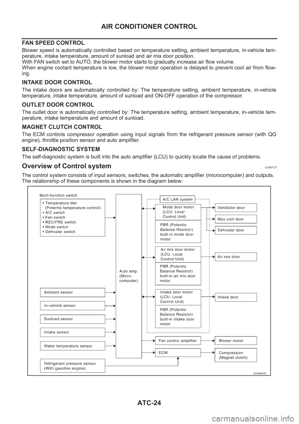
The control system consists of input sensors, switches, the automatic amplifier (microcomputer) and outputs.
The relationship of these components is shown in the diagram below:
RJIA0687E
Page 2021 of 3189
TROUBLE DIAGNOSIS
ATC-41
C
D
E
F
G
H
I
K
L
MA
B
AT C
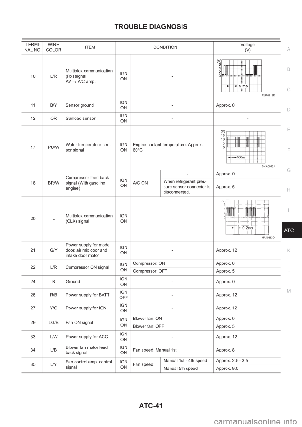
10 L/RMultiplex communication
(Rx) signal
AV → A/C amp.IGN
ON-
11 B/Y Sensor ground IGN
ON-Approx. 0
12 OR Sunload sensorIGN
ON--
17 PU/WWater temperature sen-
sor signalIGN
ONEngine coolant temperature: Approx.
60°C
18 BR/WCompressor feed back
signal (With gasoline
engine)IGN
ONA/C ON-Approx. 0
When refrigerant pres-
sure sensor connector is
disconnected.Approx. 5
20 LMultiplex communication
(CLK) signalIGN
ON-
21 G/YPower supply for mode
door, air mix door and
intake door motorIGN
ON-Approx. 12
22 L/R Compressor ON signalIGN
ONCompressor: ON Approx. 0
Compressor: OFF Approx. 5
24 B GroundIGN
ON-Approx. 0
26 R/B Power supply for BATTIGN
OFF-Approx. 12
27 Y/G Power supply for IGNIGN
ON-Approx. 12
29 LG/B Fan ON signalIGN
ONBlower fan: ON Approx. 0
Blower fan: OFF Approx. 5
33 L/W Power supply for ACCIGN
ON-Approx. 12
34 L/BBlower fan motor feed
back signalIGN
ONFan speed: Manual 1st Approx. 8
35 L/YFan control amp. control
signalIGN
ONFan speed:Manual 1st - 4th speed Approx. 2.5 - 3.5
Manual 5th speed Approx. 9.0 TERMI-
NAL NO.WIRE
COLORITEM CONDITIONVo lta g e
(V)
RJIA0213E
SKIA0056J
HAK0363D
Page 2050 of 3189
ATC-70
TROUBLE DIAGNOSIS
SYSTEM DESCRIPTION
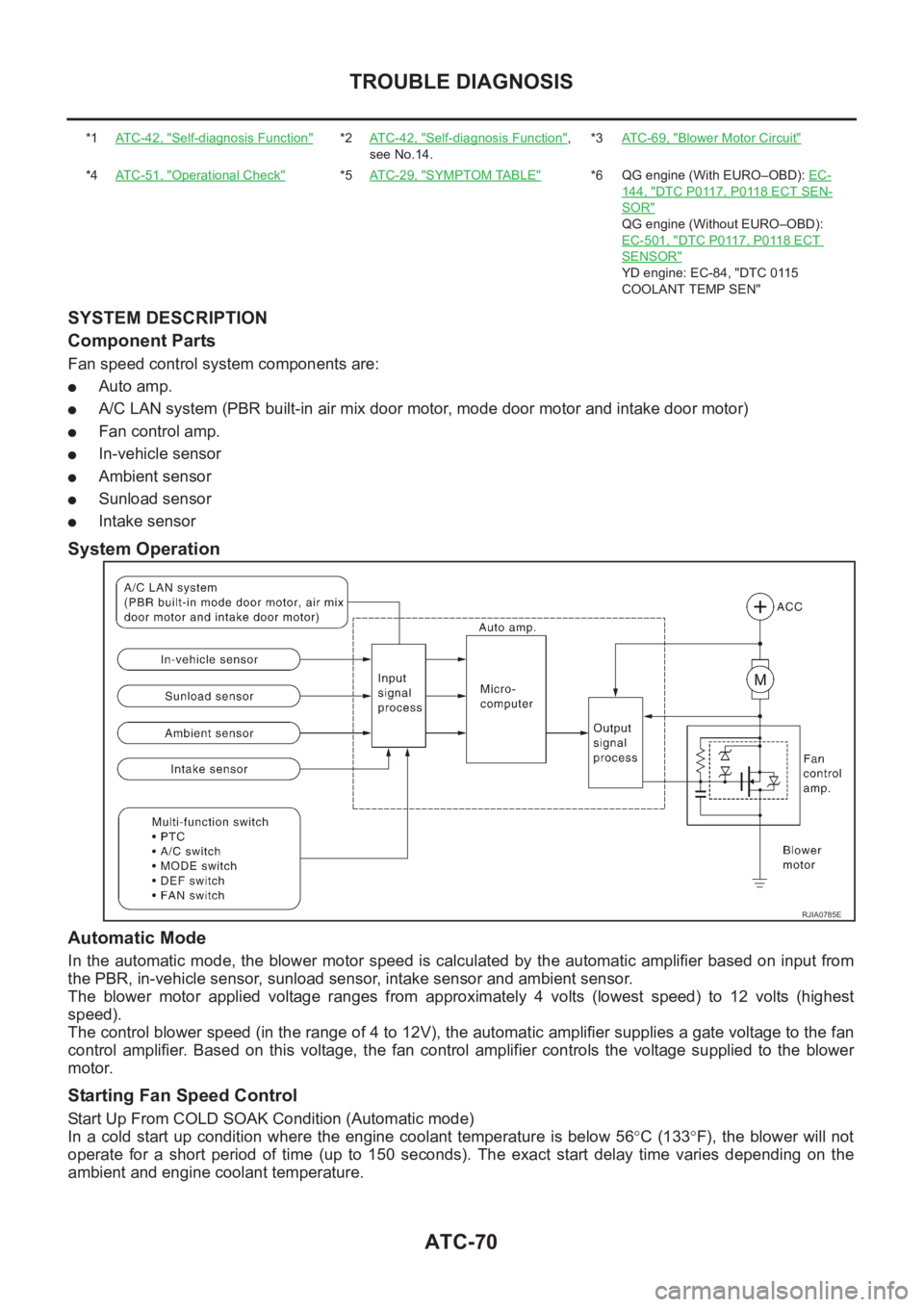
Component Parts
Fan speed control system components are:
●Auto amp.
●A/C LAN system (PBR built-in air mix door motor, mode door motor and intake door motor)
●Fan control amp.
●In-vehicle sensor
●Ambient sensor
●Sunload sensor
●Intake sensor
System Operation
Automatic Mode
In the automatic mode, the blower motor speed is calculated by the automatic amplifier based on input from
the PBR, in-vehicle sensor, sunload sensor, intake sensor and ambient sensor.
The blower motor applied voltage ranges from approximately 4 volts (lowest speed) to 12 volts (highest
speed).
The control blower speed (in the range of 4 to 12V), the automatic amplifier supplies a gate voltage to the fan
control amplifier. Based on this voltage, the fan control amplifier controls the voltage supplied to the blower
motor.
Starting Fan Speed Control
Start Up From COLD SOAK Condition (Automatic mode)
In a cold start up condition where the engine coolant temperature is below 56°C (133°F), the blower will not
operate for a short period of time (up to 150 seconds). The exact start delay time varies depending on the
ambient and engine coolant temperature.
*1AT C - 4 2 , "Self-diagnosis Function"*2AT C - 4 2 , "Self-diagnosis Function",
see No.14.*3AT C - 6 9 , "Blower Motor Circuit"
*4AT C - 5 1 , "Operational Check"*5AT C - 2 9 , "SYMPTOM TABLE"*6 QG engine (With EURO–OBD): EC-
144, "DTC P0117, P0118 ECT SEN-
SOR"
QG engine (Without EURO–OBD):
EC-501, "
DTC P0117, P0118 ECT
SENSOR"
YD engine: EC-84, "DTC 0115
COOLANT TEMP SEN"
RJIA0785E
Page 2051 of 3189
TROUBLE DIAGNOSIS
ATC-71
C
D
E
F
G
H
I
K
L
MA
B
AT C
In the most extreme case (very low ambient) the blower starting delay will be 150 seconds as described
above. After this delay, the blower will operate at low speed until the engine coolant temperature rises above
56°C (133°F), at which time the blower speed will increase to the objective speed.
Start Up From Usual or HOT SOAK Condition (Automatic mode)
The blower will begin operation momentarily after the A/C button is pushed. The blower speed will gradually
rise to the objective speed over a time period of 3 seconds or less (actual time depends on the objective
blower speed).
Blower Speed Compensation
Sunload
When the in-vehicle temperature and the set temperature are very close, the blower will be operating at low
speed. The low speed will vary depending on the sunload. During conditions of low or no sunload, the blower
low speed is usual low speed (approx. 4V). During high sunload conditions, the auto amp causes the blower
fan speed to increase.(Approx. 7V)
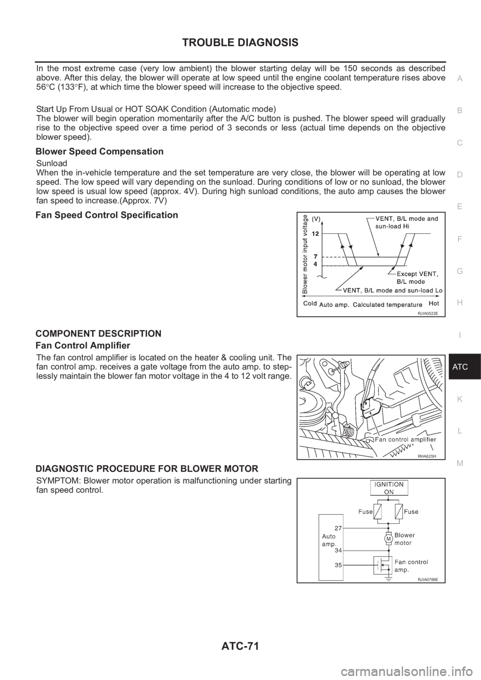
Fan Speed Control Specification
COMPONENT DESCRIPTION
Fan Control Amplifier
The fan control amplifier is located on the heater & cooling unit. The
fan control amp. receives a gate voltage from the auto amp. to step-
lessly maintain the blower fan motor voltage in the 4 to 12 volt range.
DIAGNOSTIC PROCEDURE FOR BLOWER MOTOR
SYMPTOM: Blower motor operation is malfunctioning under starting
fan speed control.
RJIA0522E
RHA625H
RJIA0786E
Page 2076 of 3189

ATC-96
TROUBLE DIAGNOSIS
*7AT C - 5 7 , "LAN System Circuit"*8ATC-69, "Blower Motor Circuit"*9AT C - 6 3 , "Air Mix Door Motor Circuit"
*10 QG engine (With EURO–OBD): EC-
144, "DTC P0117, P0118 ECT SEN-
SOR"
QG engine (Without EURO–OBD):
EC-501, "
DTC P0117, P0118 ECT
SENSOR"
YD engine: EC-84, "P0115 COOL-
ANT TEMP SEN" *11 QG engine: LC-17, "Changing
Engine Coolant"
YD engine: LC-43, "Changing
Engine Coolant" *12 QG engine: LC-17, "Changing
Engine Coolant"
YD engine: LC-43, "Changing
Engine Coolant"
Page 2102 of 3189
ATC-122
HEATER & COOLING UNIT ASSEMBLY
HEATER & COOLING UNIT ASSEMBLY
PFP:27110
Removal and InstallationEJS0020A
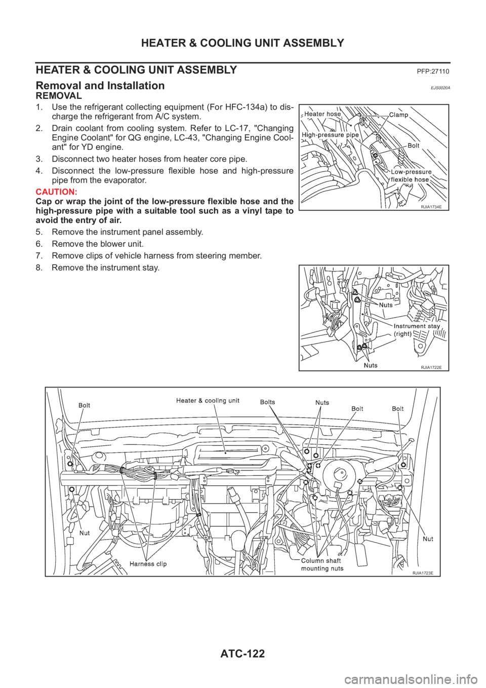
REMOVAL
1. Use the refrigerant collecting equipment (For HFC-134a) to dis-
charge the refrigerant from A/C system.
2. Drain coolant from cooling system. Refer to LC-17, "Changing
Engine Coolant" for QG engine, LC-43, "Changing Engine Cool-
ant" for YD engine.
3. Disconnect two heater hoses from heater core pipe.
4. Disconnect the low-pressure flexible hose and high-pressure
pipe from the evaporator.
CAUTION:
Cap or wrap the joint of the low-pressure flexible hose and the
high-pressure pipe with a suitable tool such as a vinyl tape to
avoid the entry of air.
5. Remove the instrument panel assembly.
6. Remove the blower unit.
7. Remove clips of vehicle harness from steering member.
8. Remove the instrument stay.
RJIA1734E
RJIA1722E
RJIA1723E
Page 2103 of 3189
HEATER & COOLING UNIT ASSEMBLY
ATC-123
C
D
E
F
G
H
I
K
L
MA
B
AT C
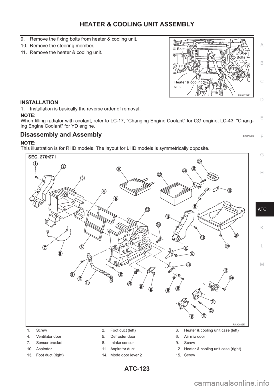
9. Remove the fixing bolts from heater & cooling unit.
10. Remove the steering member.
11. Remove the heater & cooling unit.
INSTALLATION
1. Installation is basically the reverse order of removal.
NOTE:
When filling radiator with coolant, refer to LC-17, "Changing Engine Coolant" for QG engine, LC-43, "Chang-
ing Engine Coolant" for YD engine.
Disassembly and AssemblyEJS0020B
NOTE:
This illustration is for RHD models. The layout for LHD models is symmetrically opposite.
RJIA1724E
1. Screw 2. Foot duct (left) 3. Heater & cooling unit case (left)
4. Ventilator door 5. Defroster door 6. Air mix door
7. Sensor bracket 8. Intake sensor 9. Screw
10. Aspirator 11. Aspirator duct 12. Heater & cooling unit case (right)
13. Foot duct (right) 14. Mode door lever 2 15. Screw
RJIA0825E
Page 2132 of 3189
SBR686C
Precautions
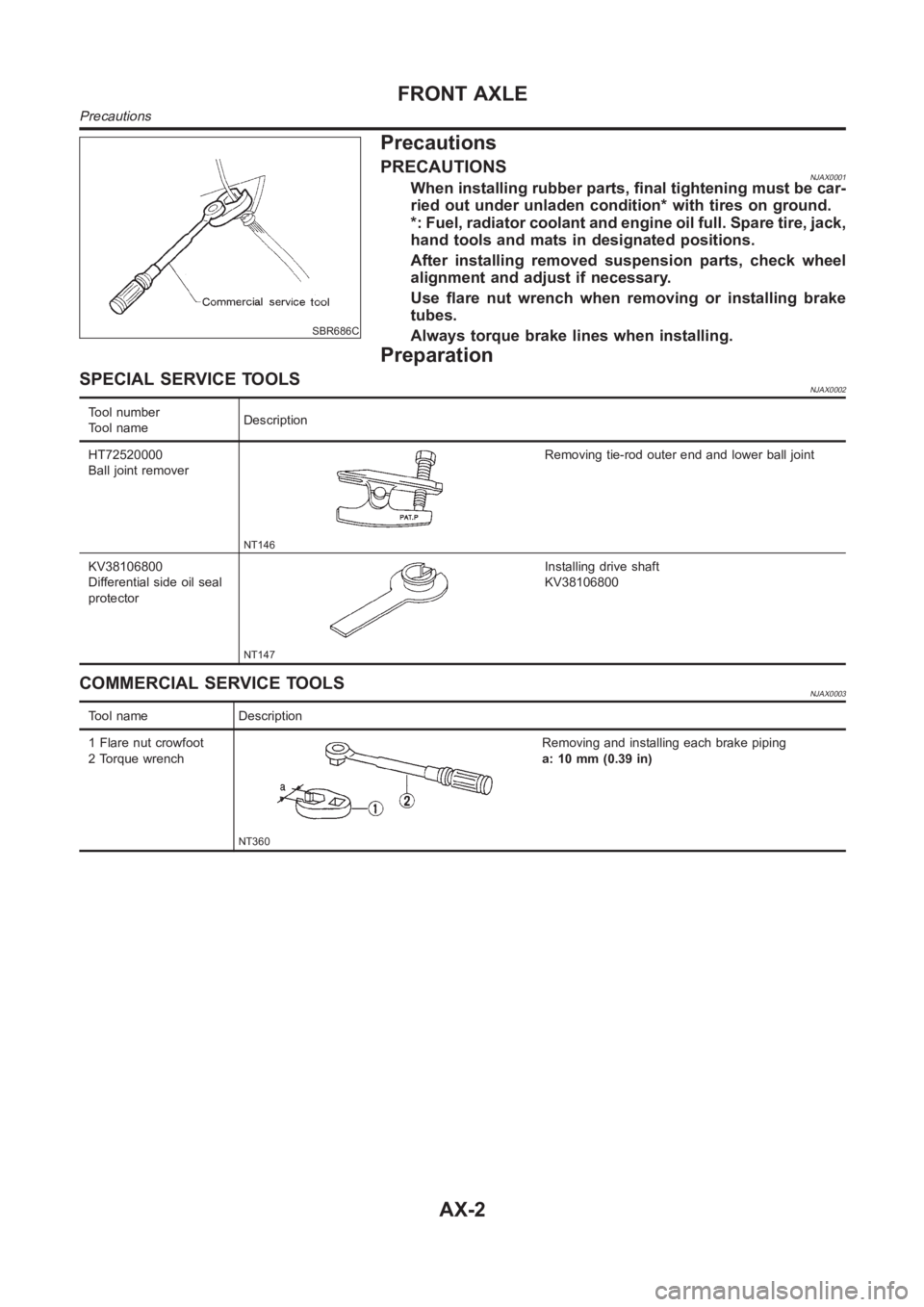
PRECAUTIONSNJAX0001When installing rubber parts, final tightening must be car-
ried out under unladen condition* with tires on ground.
*: Fuel, radiator coolant and engine oil full. Spare tire, jack,
hand tools and mats in designated positions.
After installing removed suspension parts, check wheel
alignment and adjust if necessary.
Use flare nut wrench when removing or installing brake
tubes.
Always torque brake lines when installing.
Preparation
SPECIAL SERVICE TOOLSNJAX0002
Tool number
Tool nameDescription
HT72520000
Ball joint remover
NT146
Removing tie-rod outer end and lower ball joint
KV38106800
Differential side oil seal
protector
NT147
Installing drive shaft
KV38106800
COMMERCIAL SERVICE TOOLSNJAX0003
Tool name Description
1 Flare nut crowfoot
2 Torque wrench
NT360
Removing and installing each brake piping
a: 10 mm (0.39 in)
FRONT AXLE
Precautions
AX-2
Page 2152 of 3189
SBR686C
Precautions
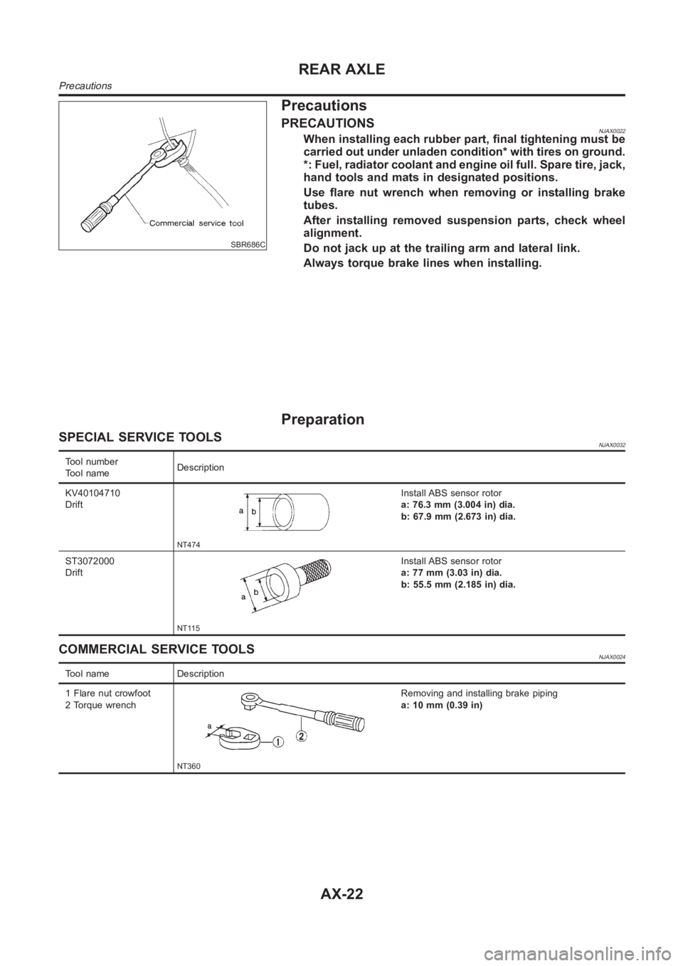
PRECAUTIONSNJAX0022When installing each rubber part, final tightening must be
carried out under unladen condition* with tires on ground.
*: Fuel, radiator coolant and engine oil full. Spare tire, jack,
hand tools and mats in designated positions.
Use flare nut wrench when removing or installing brake
tubes.
After installing removed suspension parts, check wheel
alignment.
Do not jack up at the trailing arm and lateral link.
Always torque brake lines when installing.
Preparation
SPECIAL SERVICE TOOLSNJAX0032
Tool number
Tool nameDescription
KV40104710
Drift
NT474
Install ABS sensor rotor
a: 76.3 mm (3.004 in) dia.
b: 67.9 mm (2.673 in) dia.
ST3072000
Drift
NT115
Install ABS sensor rotor
a: 77 mm (3.03 in) dia.
b: 55.5 mm (2.185 in) dia.
COMMERCIAL SERVICE TOOLSNJAX0024
Tool name Description
1 Flare nut crowfoot
2 Torque wrench
NT360
Removing and installing brake piping
a: 10 mm (0.39 in)
REAR AXLE
Precautions
AX-22