engine coolant NISSAN ALMERA N16 2003 Electronic Repair Manual
[x] Cancel search | Manufacturer: NISSAN, Model Year: 2003, Model line: ALMERA N16, Model: NISSAN ALMERA N16 2003Pages: 3189, PDF Size: 54.76 MB
Page 1121 of 3189
![NISSAN ALMERA N16 2003 Electronic Repair Manual TERMI-
NAL
NO.WIRE
COLORITEM CONDITIONDATA (DC Voltage and Pulse
Signal)
204 L Air conditioner relay[Engine is running]
Air conditioner switch is “OFF”BATTERY VOLTAGE
(11 - 14V)
[Engine is running](/img/5/57350/w960_57350-1120.png "NISSAN ALMERA N16 2003 Electronic Repair Manual TERMI-
NAL
NO.WIRE
COLORITEM CONDITIONDATA (DC Voltage and Pulse
Signal)
204 L Air conditioner relay[Engine is running]
Air conditioner switch is “OFF”BATTERY VOLTAGE
(11 - 14V)
[Engine is running")
TERMI-
NAL
NO.WIRE
COLORITEM CONDITIONDATA (DC Voltage and Pulse
Signal)
204 L Air conditioner relay[Engine is running]
Air conditioner switch is “OFF”BATTERY VOLTAGE
(11 - 14V)
[Engine is running]
Both air conditioner switch and blower fan
switch are “ON”
(Compressor is operating)Approximately 0.1V
214 W/B Glow relay Refer to “Glow Control System”, EC-188.
218 B Sensors’ ground[Engine is running]
Warm-up condition
Idle speedApproximately 0V
219 LG/R Cooling fan relay (Low)[Engine is running]
Cooling fan is not operatingBATTERY VOLTAGE
(11 - 14V)
[Engine is running]
Cooling fan is operatingApproximately 0.1V
221 LG/B Cooling fan relay (High)[Engine is running]
Cooling fan is not operating
Cooling fan is operating at low speedBATTERY VOLTAGE
(11 - 14V)
[Engine is running]
Cooling fan is operating at high speedApproximately 0.1V
223 WMass air flow sensor
power supply[Ignition switch “ON”]Approximately 5V
224 R Mass air flow sensor[Engine is running]
Warm-up condition
Idle speed1.5 - 2.0V
313 L/WElectronic control fuel
injection pump[Engine is running]
Warm-up condition
Idle speedApproximately 0.1V
314 L/RElectronic control fuel
injection pump[Engine is running]
Warm-up condition
Idle speedApproximately 0.4V
316 PUElectronic control fuel
injection pump[Engine is running]
Warm-up condition
Idle speedApproximately 2.5V
317 PElectronic control fuel
injection pump[Engine is running]
Warm-up condition
Idle speedApproximately 2.5V
325 G ECM relay (Self-shutoff)[Ignition switch “ON”]
[Ignition switch “OFF”]
For a few seconds after turning ignition switch
“OFF”Approximately 0.25V
[Ignition switch “OFF”]
A few seconds passed after turning ignition
switch “OFF”BATTERY VOLTAGE
(11 - 14V)
331 ORCrankshaft position sen-
sor (TDC) ground[Engine is running]
Warm-up condition
Idle speedApproximately 0V
334 B/REngine coolant tempera-
ture sensor ground[Ignition switch “ON”]Approximately 0V
GI
MA
EM
LC
FE
CL
MT
AT
AX
SU
BR
ST
RS
BT
HA
SC
EL
IDX
TROUBLE DIAGNOSIS — GENERAL DESCRIPTIONYD
ECM Terminals and Reference Value (Cont’d)
EC-67
Page 1122 of 3189
![NISSAN ALMERA N16 2003 Electronic Repair Manual TERMI-
NAL
NO.WIRE
COLORITEM CONDITIONDATA (DC Voltage and Pulse
Signal)
337
338
350
351W/L
PU/W
GY
OR/BEGR volume control
valve[Engine is running]
Warm-up condition
Idle speed0.1 - 14V
(Voltage signa](/img/5/57350/w960_57350-1121.png "NISSAN ALMERA N16 2003 Electronic Repair Manual TERMI-
NAL
NO.WIRE
COLORITEM CONDITIONDATA (DC Voltage and Pulse
Signal)
337
338
350
351W/L
PU/W
GY
OR/BEGR volume control
valve[Engine is running]
Warm-up condition
Idle speed0.1 - 14V
(Voltage signa")
TERMI-
NAL
NO.WIRE
COLORITEM CONDITIONDATA (DC Voltage and Pulse
Signal)
337
338
350
351W/L
PU/W
GY
OR/BEGR volume control
valve[Engine is running]
Warm-up condition
Idle speed0.1 - 14V
(Voltage signals of each ECM
terminals differ according to the
control position of EGR volume
control valve.)
344 WCrankshaft position sen-
sor (TDC)[Engine is running]
Warm-up condition
Idle speedApproximately 0V
SEF333Y
[Engine is running]
Warm-up condition
Engine speed is 2,000 rpmApproximately 0V
SEF334Y
347 L/BEngine coolant tempera-
ture sensor[Engine is running]Approximately 0 - 4.8V
Output voltage varies with
engine coolant temperature
403 R/L Air conditioner switch[Engine is running]
Air conditioner switch is “OFF”BATTERY VOLTAGE
(11 - 14V)
[Engine is running]
Both air conditioner switch and blower fan
switch are “ON”
(Compressor is operating)Approximately 0.1V
405 R/G Stop lamp switch[Ignition switch “ON”]
Brake pedal fully releasedApproximately 0V
[Ignition switch “ON”]
Brake pedal depressedBATTERY VOLTAGE
(11 - 14V)
416 Y/BBrake pedal position
switch[Ignition switch “ON”]
Brake pedal fully releasedBATTERY VOLTAGE
(11 - 14V)
[Ignition switch “ON”]
Brake pedal depressedApproximately 0V
TROUBLE DIAGNOSIS — GENERAL DESCRIPTIONYD
ECM Terminals and Reference Value (Cont’d)
EC-68
Page 1138 of 3189
SEF594K
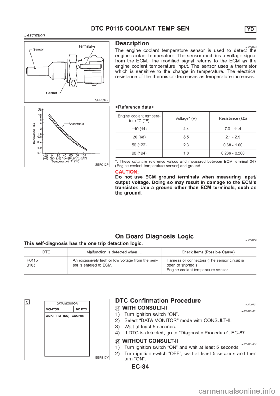
DescriptionNJEC0649The engine coolant temperature sensor is used to detect the
engine coolant temperature. The sensor modifies a voltage signal
from the ECM. The modified signal returns to the ECM as the
engine coolant temperature input. The sensor uses a thermistor
which is sensitive to the change in temperature. The electrical
resistance of the thermistor decreases as temperature increases.
SEF012P
Engine coolant tempera-
ture °C (°F)Voltage* (V) Resistance (kΩ)
−10 (14) 4.4 7.0 - 11.4
20 (68) 3.5 2.1 - 2.9
50 (122) 2.3 0.68 - 1.00
90 (194) 1.0 0.236 - 0.260
*: These data are reference values and measured between ECM terminal 347
(Engine coolant temperature sensor) and ground.
CAUTION:
Do not use ECM ground terminals when measuring input/
output voltage. Doing so may result in damage to the ECM’s
transistor. Use a ground other than ECM terminals, such as
the ground.
On Board Diagnosis LogicNJEC0650This self-diagnosis has the one trip detection logic.
DTC Malfunction is detected when ... Check Items (Possible Cause)
P0115
0103An excessively high or low voltage from the sen-
sor is entered to ECM.Harness or connectors (The sensor circuit is
open or shorted.)
Engine coolant temperature sensor
SEF817Y
DTC Confirmation ProcedureNJEC0651WITH CONSULT-IINJEC0651S011) Turn ignition switch “ON”.
2) Select “DATA MONITOR” mode with CONSULT-II.
3) Wait at least 5 seconds.
4) If DTC is detected, go to “Diagnostic Procedure”, EC-87.
WITHOUT CONSULT-IINJEC0651S021) Turn ignition switch “ON” and wait at least 5 seconds.
2) Turn ignition switch “OFF”, wait at least 5 seconds and then
turn “ON”.
DTC P0115 COOLANT TEMP SENYD
Description
EC-84
Page 1141 of 3189
Diagnostic ProcedureNJEC0653
1 CHECK ECTS POWER SUPPLY CIRCUIT
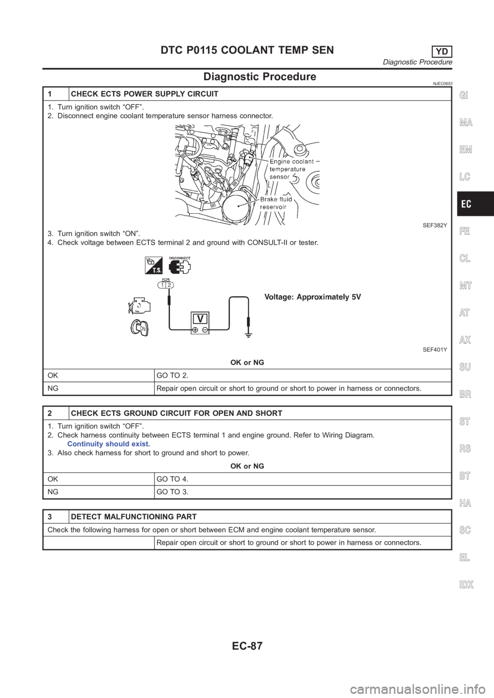
1. Turn ignition switch “OFF”.
2. Disconnect engine coolant temperature sensor harness connector.
SEF382Y
3. Turn ignition switch “ON”.
4. Check voltage between ECTS terminal 2 and ground with CONSULT-II or tester.
SEF401Y
OK or NG
OK GO TO 2.
NG Repair open circuit or short to ground or short to power in harness or connectors.
2 CHECK ECTS GROUND CIRCUIT FOR OPEN AND SHORT
1. Turn ignition switch “OFF”.
2. Check harness continuity between ECTS terminal 1 and engine ground. Refer to Wiring Diagram.
Continuity should exist.
3. Also check harness for short to ground and short to power.
OK or NG
OK GO TO 4.
NG GO TO 3.
3 DETECT MALFUNCTIONING PART
Check the following harness for open or short between ECM and engine coolant temperature sensor.
Repair open circuit or short to ground or short to power in harness or connectors.
GI
MA
EM
LC
FE
CL
MT
AT
AX
SU
BR
ST
RS
BT
HA
SC
EL
IDX
DTC P0115 COOLANT TEMP SENYD
Diagnostic Procedure
EC-87
Page 1142 of 3189
4 CHECK ENGINE COOLANT TEMPERATURE SENSOR
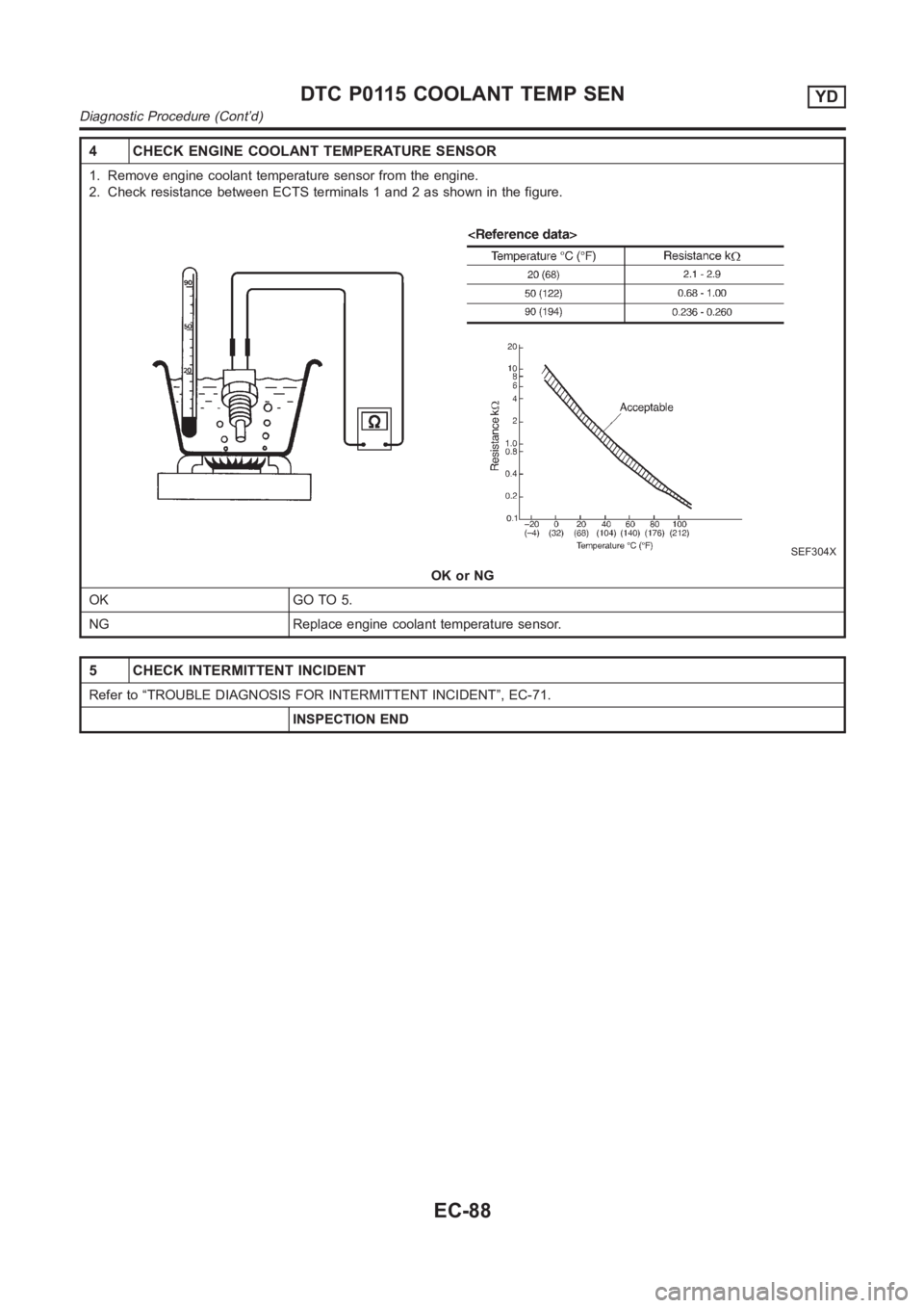
1. Remove engine coolant temperature sensor from the engine.
2. Check resistance between ECTS terminals 1 and 2 as shown in the figure.
SEF304X
OK or NG
OK GO TO 5.
NG Replace engine coolant temperature sensor.
5 CHECK INTERMITTENT INCIDENT
Refer to “TROUBLE DIAGNOSIS FOR INTERMITTENT INCIDENT”, EC-71.
INSPECTION END
DTC P0115 COOLANT TEMP SENYD
Diagnostic Procedure (Cont’d)
EC-88
Page 1184 of 3189
DescriptionNJEC0660SYSTEM DESCRIPTIONNJEC0660S01
Sensor Input signal to ECM ECM function Actuator
Vehicle speed sensor Vehicle speed
Cooling fan
controlCooling fan relay Engine coolant temperature sensor Engine coolant temperature
Air conditioner switch Air conditioner “ON” signal
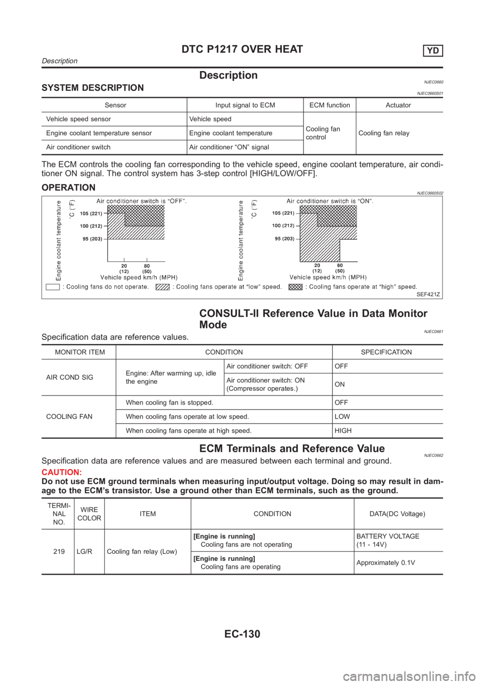
The ECM controls the cooling fan corresponding to the vehicle speed, engine coolant temperature, air condi-
tioner ON signal. The control system has 3-step control [HIGH/LOW/OFF].
OPERATIONNJEC0660S02
SEF421Z
CONSULT-II Reference Value in Data Monitor
Mode
NJEC0661Specification data are reference values.
MONITOR ITEM CONDITION SPECIFICATION
AIRCONDSIGEngine: After warming up, idle
the engineAir conditioner switch: OFF OFF
Air conditioner switch: ON
(Compressor operates.)ON
COOLING FANWhen cooling fan is stopped. OFF
When cooling fans operate at low speed. LOW
When cooling fans operate at high speed. HIGH
ECM Terminals and Reference ValueNJEC0662Specification data are reference values and are measured between each terminal and ground.
CAUTION:
Do not use ECM ground terminals when measuring input/output voltage. Doing so may result in dam-
age to the ECM’s transistor. Use a ground other than ECM terminals, such as the ground.
TERMI-
NAL
NO.WIRE
COLORITEM CONDITION DATA(DC Voltage)
219 LG/R Cooling fan relay (Low)[Engine is running]
Cooling fans are not operatingBATTERY VOLTAGE
(11 - 14V)
[Engine is running]
Cooling fans are operatingApproximately 0.1V
DTC P1217 OVER HEATYD
Description
EC-130
Page 1185 of 3189
![NISSAN ALMERA N16 2003 Electronic Repair Manual TERMI-
NAL
NO.WIRE
COLORITEM CONDITION DATA(DC Voltage)
221 LG/B Cooling fan relay (High)[Engine is running]
Cooling fans are not operating
Cooling fans are operating at low speedBATTERY VOLTAGE
(11 -](/img/5/57350/w960_57350-1184.png "NISSAN ALMERA N16 2003 Electronic Repair Manual TERMI-
NAL
NO.WIRE
COLORITEM CONDITION DATA(DC Voltage)
221 LG/B Cooling fan relay (High)[Engine is running]
Cooling fans are not operating
Cooling fans are operating at low speedBATTERY VOLTAGE
(11 -")
TERMI-
NAL
NO.WIRE
COLORITEM CONDITION DATA(DC Voltage)
221 LG/B Cooling fan relay (High)[Engine is running]
Cooling fans are not operating
Cooling fans are operating at low speedBATTERY VOLTAGE
(11 - 14V)
[Engine is running]
Cooling fans are operating at high speedApproximately 0.1V
On Board Diagnosis LogicNJEC0663This diagnosis continuously monitors the engine coolant temperature.
If the cooling fan or another component in the cooling system malfunctions, engine coolant temperature will
rise.
When the engine coolant temperature reaches an abnormally high temperature condition, a malfunction is
indicated.
This self-diagnosis has the one trip detection logic.
DTC Malfunction is detected when ... Check Items (Possible Cause)
P1217
0208Cooling fan does not operate properly (Overheat).
Cooling fan system does not operate properly
(Overheat).
Engine coolant was not added to the system using
the proper filling method.Harness or connectors
(The cooling fan circuit is open or shorted.)
Cooling fan
Radiator hose
Radiator
Radiator cap
Water pump
Thermostat
Engine coolant temperature sensor
For more information, refer to “MAIN 12 CAUSES OF
OVERHEATING”, EC-144.
CAUTION:
When a malfunction is indicated, be sure to replace the coolant following the procedure in the LC-43,
“Changing Engine Coolant”. Also, replace the engine oil.
1) Fill radiator with coolant up to specified level with a filling speed of 2liters per minute. Be sure
to use coolant with the proper mixture ratio. Refer to MA-21, “Engine Coolant Mixture Ratio”.
2) After refilling coolant, run engine to ensure that no water-flow noise is emitted.
GI
MA
EM
LC
FE
CL
MT
AT
AX
SU
BR
ST
RS
BT
HA
SC
EL
IDX
DTC P1217 OVER HEATYD
ECM Terminals and Reference Value (Cont’d)
EC-131
Page 1186 of 3189
AEC640
Overall Function Check
SEF111X
SEC163BA
MEC475B
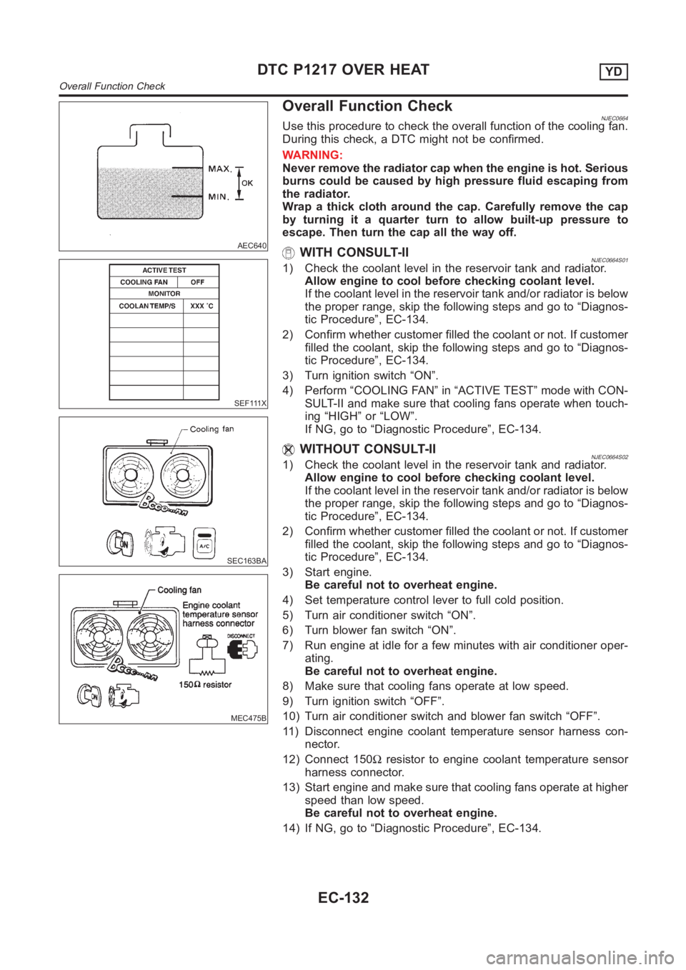
NJEC0664Use this procedure to check the overall function of the cooling fan.
During this check, a DTC might not be confirmed.
WARNING:
Never remove the radiator cap when the engine is hot. Serious
burns could be caused by high pressure fluid escaping from
the radiator.
Wrap a thick cloth around the cap. Carefully remove the cap
by turning it a quarter turn to allow built-up pressure to
escape. Then turn the cap all the way off.
WITH CONSULT-IINJEC0664S011) Check the coolant level in the reservoir tank and radiator.
Allow engine to cool before checking coolant level.
If the coolant level in the reservoir tank and/or radiator is below
the proper range, skip the following steps and go to “Diagnos-
tic Procedure”, EC-134.
2) Confirm whether customer filled the coolant or not. If customer
filled the coolant, skip the following steps and go to “Diagnos-
tic Procedure”, EC-134.
3) Turn ignition switch “ON”.
4) Perform “COOLING FAN” in “ACTIVE TEST” mode with CON-
SULT-II and make sure that cooling fans operate when touch-
ing “HIGH” or “LOW”.
If NG, go to “Diagnostic Procedure”, EC-134.
WITHOUT CONSULT-IINJEC0664S021) Check the coolant level in the reservoir tank and radiator.
Allow engine to cool before checking coolant level.
If the coolant level in the reservoir tank and/or radiator is below
the proper range, skip the following steps and go to “Diagnos-
tic Procedure”, EC-134.
2) Confirm whether customer filled the coolant or not. If customer
filled the coolant, skip the following steps and go to “Diagnos-
tic Procedure”, EC-134.
3) Start engine.
Be careful not to overheat engine.
4) Set temperature control lever to full cold position.
5) Turn air conditioner switch “ON”.
6) Turn blower fan switch “ON”.
7) Run engine at idle for a few minutes with air conditioner oper-
ating.
Be careful not to overheat engine.
8) Make sure that cooling fans operate at low speed.
9) Turn ignition switch “OFF”.
10) Turn air conditioner switch and blower fan switch “OFF”.
11) Disconnect engine coolant temperature sensor harness con-
nector.
12) Connect 150Ωresistor to engine coolant temperature sensor
harness connector.
13) Start engine and make sure that cooling fans operate at higher
speed than low speed.
Be careful not to overheat engine.
14) If NG, go to “Diagnostic Procedure”, EC-134.
DTC P1217 OVER HEATYD
Overall Function Check
EC-132
Page 1190 of 3189
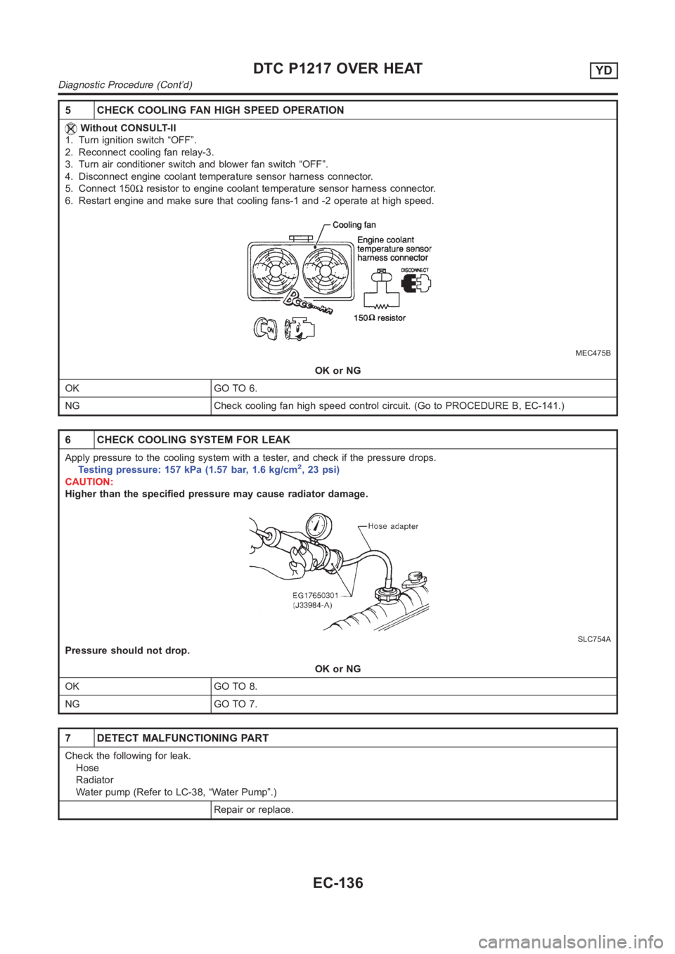
5 CHECK COOLING FAN HIGH SPEED OPERATION
Without CONSULT-II
1. Turn ignition switch “OFF”.
2. Reconnect cooling fan relay-3.
3. Turn air conditioner switch and blower fan switch “OFF”.
4. Disconnect engine coolant temperature sensor harness connector.
5. Connect 150Ωresistor to engine coolant temperature sensor harness connector.
6. Restart engine and make sure that cooling fans-1 and -2 operate at high speed.
MEC475B
OK or NG
OK GO TO 6.
NG Check cooling fan high speed control circuit. (Go to PROCEDURE B, EC-141.)
6 CHECK COOLING SYSTEM FOR LEAK
Apply pressure to the cooling system with a tester, and check if the pressure drops.
Testing pressure: 157 kPa (1.57 bar, 1.6 kg/cm2,23psi)
CAUTION:
Higher than the specified pressure may cause radiator damage.
SLC754A
Pressure should not drop.
OK or NG
OK GO TO 8.
NG GO TO 7.
7 DETECT MALFUNCTIONING PART
Check the following for leak.
Hose
Radiator
Water pump (Refer to LC-38, “Water Pump”.)
Repair or replace.
DTC P1217 OVER HEATYD
Diagnostic Procedure (Cont’d)
EC-136
Page 1192 of 3189
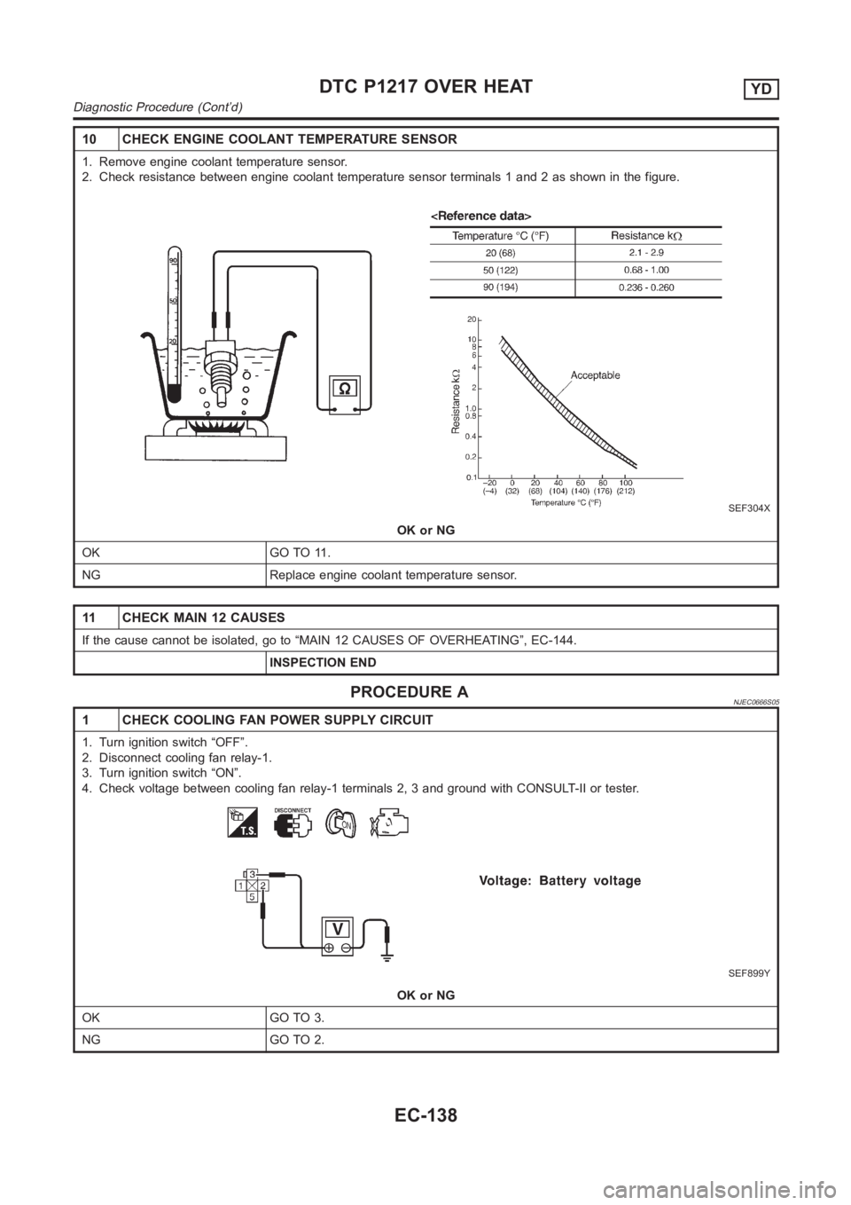
10 CHECK ENGINE COOLANT TEMPERATURE SENSOR
1. Remove engine coolant temperature sensor.
2. Check resistance between engine coolant temperature sensor terminals1 and 2 as shown in the figure.
SEF304X
OK or NG
OK GO TO 11.
NG Replace engine coolant temperature sensor.
11 CHECK MAIN 12 CAUSES
If the cause cannot be isolated, go to “MAIN 12 CAUSES OF OVERHEATING”, EC-144.
INSPECTION END
PROCEDURE ANJEC0666S05
1 CHECK COOLING FAN POWER SUPPLY CIRCUIT
1. Turn ignition switch “OFF”.
2. Disconnect cooling fan relay-1.
3. Turn ignition switch “ON”.
4. Check voltage between cooling fan relay-1 terminals 2, 3 and ground withCONSULT-II or tester.
SEF899Y
OK or NG
OK GO TO 3.
NG GO TO 2.
DTC P1217 OVER HEATYD
Diagnostic Procedure (Cont’d)
EC-138