engine coolant NISSAN ALMERA N16 2003 Electronic User Guide
[x] Cancel search | Manufacturer: NISSAN, Model Year: 2003, Model line: ALMERA N16, Model: NISSAN ALMERA N16 2003Pages: 3189, PDF Size: 54.76 MB
Page 77 of 3189
SMA089D
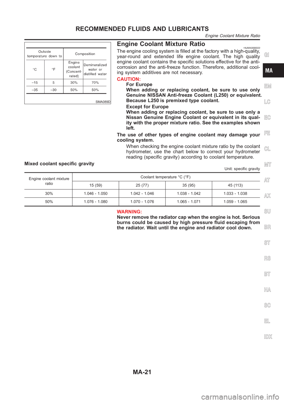
Engine Coolant Mixture Ratio=NJMA0006S03The engine cooling system is filled at the factory with a high-quality,
year-round and extended life engine coolant. The high quality
engine coolant contains the specific solutions effective for the anti-
corrosion and the anti-freeze function. Therefore, additional cool-
ing system additives are not necessary.
CAUTION:
For Europe
When adding or replacing coolant, be sure to use only
Genuine NISSAN Anti-freeze Coolant (L250) or equivalent.
Because L250 is premixed type coolant.
Except for Europe
When adding or replacing coolant, be sure to use only a
Nissan Genuine Engine Coolant or equivalent in its qual-
ity with the proper mixture ratio. See the examples shown
left.
The use of other types of engine coolant may damage your
cooling system.
When checking the engine coolant mixture ratio by the coolant
hydrometer, use the chart below to correct your hydrometer
reading (specific gravity) according to coolant temperature.
Mixed coolant specific gravity
Unit: specific gravity
Engine coolant mixture
ratioCoolant temperature °C (°F)
15 (59) 25 (77) 35 (95) 45 (113)
30% 1.046 - 1.050 1.042 - 1.046 1.038 - 1.042 1.033 - 1.038
50% 1.076 - 1.080 1.070 - 1.076 1.065 - 1.071 1.059 - 1.065
WARNING:
Never remove the radiator cap when the engine is hot. Serious
burns could be caused by high pressure fluid escaping from
the radiator. Wait until the engine and radiator cool down.
GI
EM
LC
EC
FE
CL
MT
AT
AX
SU
BR
ST
RS
BT
HA
SC
EL
IDX
RECOMMENDED FLUIDS AND LUBRICANTS
Engine Coolant Mixture Ratio
MA-21
Page 79 of 3189
EM-1
ENGINE MECHANICAL
B ENGINE
CONTENTS
C
D
E
F
G
H
I
J
K
L
M
SECTION
A
EM
ENGINE MECHANICAL
QG
PRECAUTIONS .......................................................... 3
Precautions for Drain Coolant .................................. 3
Precautions for Disconnecting Fuel Piping .............. 3
Precautions for Removal and Disassembly ............. 3
Precautions for Inspection, Repair and Replace-
ment ......................................................................... 3
Precautions for Assembly and Installation ............... 3
Parts Requiring Angular Tightening ......................... 3
Precautions for Liquid Gasket .................................. 4
REMOVAL OF LIQUID GASKET SEALING .......... 4
LIQUID GASKET APPLICATION PROCEDURE ..... 4
PREPARATION ........................................................... 5
Special Service Tools ............................................... 5
Commercial Service Tools ........................................ 7
NOISE, VIBRATION, AND HARSHNESS (NVH)
TROUBLESHOOTING ................................................ 9
NVH Troubleshooting —Engine Noise ..................... 9
Use the Chart Below to Help You Find the Cause
of the Symptom. ..................................................... 10
DRIVE BELTS ............................................................11
Checking Drive Belts ............................................... 11
Tension Adjustment ................................................ 12
POWER STEERING PUMP AND WATER PUMP
BELT ................................................................... 12
ALTERNATOR AND AIR CONDITIONER COM-
PRESSOR BELT ................................................. 12
Removal and Installation ........................................ 13
REMOVAL ........................................................... 13
INSTALLATION ................................................... 13
AIR CLEANER AND AIR DUCT ............................... 14
Removal and Installation ........................................ 14
REMOVAL ........................................................... 14
INSTALLATION ................................................... 14
Changing Air Cleaner Element ............................... 15
INTAKE MANIFOLD ................................................. 16
Removal and Installation ........................................ 16
REMOVAL ........................................................... 16
INSPECTION AFTER REMOVAL ....................... 18
INSTALLATION ................................................... 18EXHAUST MANIFOLD AND CATALYTIC CON-
VERTER .................................................................... 19
Removal and Installation ........................................ 19
REMOVAL ........................................................... 19
INSPECTION AFTER REMOVAL ....................... 20
INSTALLATION ................................................... 20
Disassembly and Assembly .................................... 21
DISASSEMBLY ................................................... 21
ASSEMBLY ......................................................... 21
OIL PAN AND OIL STRAINER ..............................
... 22
Removal and Installation ........................................ 22
REMOVAL ........................................................... 22
INSTALLATION ................................................... 23
INSPECTION AFTER INSTALLATION ................ 23
IGNITION COIL ......................................................... 24
Removal and Installation ........................................ 24
REMOVAL ........................................................... 24
INSTALLATION ................................................... 24
SPARK PLUG (CONVENTIONAL) ........................... 25
Removal and Installation ........................................ 25
REMOVAL ........................................................... 25
INSPECTION AFTER REMOVAL ....................... 25
INSTALLATION ................................................... 25
FUEL INJECTOR AND FUEL TUBE ........................ 26
Removal and Installation ........................................ 26
REMOVAL ........................................................... 26
INSTALLATION ................................................... 27
INSPECTION AFTER INSTALLATION ................ 28
ROCKER COVER ..................................................... 29
Removal and Installation ........................................ 29
REMOVAL ........................................................... 29
INSTALLATION ................................................... 30
CAMSHAFT .............................................................. 32
Removal and Installation ........................................ 32
REMOVAL ........................................................... 32
INSTALLATION ................................................... 35
Page 94 of 3189
![NISSAN ALMERA N16 2003 Electronic User Guide EM-16
[QG]
INTAKE MANIFOLD
INTAKE MANIFOLD
PFP:14003
Removal and InstallationEBS00LQ3
REMOVAL
WARNING:
To avoid the danger of being scalded, never drain the coolant when the engine is hot.
1. Release](/img/5/57350/w960_57350-93.png "NISSAN ALMERA N16 2003 Electronic User Guide EM-16
[QG]
INTAKE MANIFOLD
INTAKE MANIFOLD
PFP:14003
Removal and InstallationEBS00LQ3
REMOVAL
WARNING:
To avoid the danger of being scalded, never drain the coolant when the engine is hot.
1. Release")
EM-16
[QG]
INTAKE MANIFOLD
INTAKE MANIFOLD
PFP:14003
Removal and InstallationEBS00LQ3
REMOVAL
WARNING:
To avoid the danger of being scalded, never drain the coolant when the engine is hot.
1. Release fuel pressure.
Refer to EC-34, "
FUEL PRESSURE RELEASE" (WITH EURO-OBD), EC-427, "FUEL PRESSURE
RELEASE" (WITHOUT EURO-OBD).
2. Remove air duct and air cleaner case.
Refer to EM-14, "
Removal and Installation" .
3. Disconnect harness on engine top surface, and move it aside.
4. Disconnect fuel injector/fuel tube assembly from intake manifold, and move it aside.
●It is not necessary to disconnect fuel hose.
5. Disconnect the following vacuum hoses.
6. Disconnect blow-by hose (between intake manifold collector and rocker cover).
KBIA1363E
1. Electric throttle control actuator 2. Gasket 3. Intake manifold collector
4.EVAP canister purge volume control
solenoid valve5. Vacuum hose 6. Vacuum hose
7. Hose clamp 8. Intake manifold support (front) 9. Harness bracket
10. Vacuum hose 11. Intake manifold 12. PCV hose
13. Gasket 14. Vacuum hose 15. Gasket
16. Intake manifold support (rear) 17. Harness bracket 18. Intake manifold support (engine rear)
19. Grounding wire
Page 126 of 3189
![NISSAN ALMERA N16 2003 Electronic User Guide EM-48
[QG]
TIMING CHAIN
2. Disconnect battery ground cable.
3. Remove undercover, front RH wheel and RH splash cover.
4. Drain engine coolant from radiator and cylinder block. Refer to LC-17, "Cha](/img/5/57350/w960_57350-125.png "NISSAN ALMERA N16 2003 Electronic User Guide EM-48
[QG]
TIMING CHAIN
2. Disconnect battery ground cable.
3. Remove undercover, front RH wheel and RH splash cover.
4. Drain engine coolant from radiator and cylinder block. Refer to LC-17, \"Cha")
EM-48
[QG]
TIMING CHAIN
2. Disconnect battery ground cable.
3. Remove undercover, front RH wheel and RH splash cover.
4. Drain engine coolant from radiator and cylinder block. Refer to LC-17, "Changing Engine Coolant".
5. Drain engine oil from oil pan.
6. Remove drive belt. Refer to EM-13, "
Removal and Installation" .
7. Remove power steering pump from adjusting bar.
8. Remove alternator. SC-33, "Removal and Installation".
9. Remove ignition coils. Refer to EM-24, "
IGNITION COIL" .
10. Remove rocker cover. Refer to EM-29, "
Removal and Installation" .
11. Remove oil level gauge.
12. Remove exhaust front tube. Refer to FE-10, "Removal and Installation".
13. Remove center member.
14. Remove gusset.
15. Remove rear plate (lower) (A/T models).
16. Remove oil pan and oil strainer. Refer to EM-22, "
Removal and Installation" .
17. For safe operation, and to reduce load to mount insulator, install removed center member again.
18. Remove engine front-side (right side of vehicle) engine mount. Refer to EM-67, "
ENGINE ASSEMBLY" .
a. Remove any parts that cause difficulties for operation around mount, or perform transfer.
b. Support cylinder block bottom surface with a transmission jack.
CAUTION:
●When applying jack, use a wooden block to avoid damage to oil pan mounting surface.
●While performing following operations, support engine front-side with jack.
c. Separate engine mounting insulator and bracket.
d. Remove engine mounting bracket.
19. Remove cylinder head front cover.
●Move harness which was previously fixed on front surface.
20. Remove auxiliary bolts of cylinder head.
21. Set the No. 1 cylinder to the compression TDC.
a. Turn the crankshaft pulley clockwise, and align the timing indica-
tor of the gear case to the timing mark of the crankshaft pulley.
PBIC0557E
PBIC0750E
Page 136 of 3189
![NISSAN ALMERA N16 2003 Electronic User Guide EM-58
[QG]
CYLINDER HEAD
8. Install spark plug, ignition coil and harness connectors.
Removal and InstallationEBS00LQI
REMOVAL
1. Release fuel pressure. Refer to EC-34, "FUEL PRESSURE RELEA](/img/5/57350/w960_57350-135.png "NISSAN ALMERA N16 2003 Electronic User Guide EM-58
[QG]
CYLINDER HEAD
8. Install spark plug, ignition coil and harness connectors.
Removal and InstallationEBS00LQI
REMOVAL
1. Release fuel pressure. Refer to EC-34, \"FUEL PRESSURE RELEA")
EM-58
[QG]
CYLINDER HEAD
8. Install spark plug, ignition coil and harness connectors.
Removal and InstallationEBS00LQI
REMOVAL
1. Release fuel pressure. Refer to EC-34, "FUEL PRESSURE RELEASE" (WITH EURO-OBD), EC-427,
"FUEL PRESSURE RELEASE" (WITHOUT EURO-OBD).
2. Remove undercover.
3. Drain engine coolant. Refer to LC-17, "Changing Engine Coolant".
4. Remove the following components and related parts:
●Intake manifold and intake manifold collector. Refer to EM-16, "INTAKE MANIFOLD" .
●Exhaust manifold and catalytic converter. Refer to EM-19, "EXHAUST MANIFOLD AND CATALYTIC
CONVERTER" .
●Ignition coil. Refer to EM-24, "IGNITION COIL" .
●Rocker cover. Refer to EM-29, "ROCKER COVER" .
●Camshaft. Refer to EM-32, "CAMSHAFT" .
●Alternator bracket. Refer to SC-33, "Removal and Installation".
PBIC0972E
1. Rear engine slinger 2. Cylinder head bolt 3. Washer
4. Auxiliary bolt of cylinder head 5. Cylinder head gasket 6. Cylinder head assembly
Page 138 of 3189
![NISSAN ALMERA N16 2003 Electronic User Guide EM-60
[QG]
CYLINDER HEAD
3. Tighten cylinder auxiliary bolts (11) to (14) in numerical order
shown in figure.
●Pay attention to shank length under bolt head. [11: 20 mm
(0.79 in), 12 - 14:](/img/5/57350/w960_57350-137.png "NISSAN ALMERA N16 2003 Electronic User Guide EM-60
[QG]
CYLINDER HEAD
3. Tighten cylinder auxiliary bolts (11) to (14) in numerical order
shown in figure.
●Pay attention to shank length under bolt head. [11: 20 mm
(0.79 in), 12 - 14:")
EM-60
[QG]
CYLINDER HEAD
3. Tighten cylinder auxiliary bolts (11) to (14) in numerical order
shown in figure.
●Pay attention to shank length under bolt head. [11: 20 mm
(0.79 in), 12 - 14: 25 mm (0.98 in)]
Disassembly and AssemblyEBS00LQJ
CAUTION:
●When installing camshafts, chain tensioners, oil seals or other sliding parts, lubricate contacting
surface with new engine oil.
●Apply new engine oil to threads and seat surface when installing cylinder head, camshaft
sprocket, crankshaft pulley and camshaft bracket.
●Attach tags to valve lifters so as not to mix them up.
DISASSEMBLY
1. Remove adjusting shim (if so equipped) and valve lifter.
●Confirm installation point.
SEM900F
PBIC0973E
1. Cylinder head 2. Valve (INT) 3. Valve (EXH)
4. Valve seat 5. Engine coolant temperature sensor 6. Copper washer
7. Spark plug tube 8. Spark plug
Page 139 of 3189
![NISSAN ALMERA N16 2003 Electronic User Guide CYLINDER HEAD
EM-61
[QG]
C
D
E
F
G
H
I
J
K
L
MA
EM
2. Remove valve collet.
●Compress valve spring with valve spring compressor (special
service tool). Remove valve collet with magnet driver.
3. Remo](/img/5/57350/w960_57350-138.png "NISSAN ALMERA N16 2003 Electronic User Guide CYLINDER HEAD
EM-61
[QG]
C
D
E
F
G
H
I
J
K
L
MA
EM
2. Remove valve collet.
●Compress valve spring with valve spring compressor (special
service tool). Remove valve collet with magnet driver.
3. Remo")
CYLINDER HEAD
EM-61
[QG]
C
D
E
F
G
H
I
J
K
L
MA
EM
2. Remove valve collet.
●Compress valve spring with valve spring compressor (special
service tool). Remove valve collet with magnet driver.
3. Remove valve spring retainer and valve spring.
4. Push valve stem to combustion chamber side, and remove
valve.
●Inspect valve guide clearance before removal. Refer to EM-
63, "VALVE GUIDE CLEARANCE" .
●Confirm installation point.
5. Remove valve oil seal with valve oil seal puller (special service
tool).
6. Remove valve spring seat.
7. When valve seat must be replaced, refer to EM-64, "
VA LV E
SEAT REPLACEMENT" .
8. When valve guide must be replaced, refer to EM-63, "
VA LV E
GUIDE REPLACEMENT" .
9. Remove spark plug with spark plug wrench (commercial service
tool).
10. Remove engine coolant temperature sensor.
CAUTION:
Do not shock it.
11. Remove spark plug tube, as necessary.
●Using a pair of pliers, pull spark plug tube out of cylinder head.
CAUTION:
●Take care not to damage cylinder head.
●Once removed, a spark plug tube will be deformed and cannot be reused. Do not remove it
unless absolutely necessary.
ASSEMBLY
1. Install valve guide. Refer to EM-63, "VALVE GUIDE REPLACEMENT" .
2. Install valve seat. Refer to EM-64, "
VALVE SEAT REPLACEMENT" .
3. Install valve oil seal.
●Install with valve oil seal drift (special service tool) to match
dimension in illustration.
4. Install valve spring seat.
5. Install valve.
●Install larger diameter to intake side.
6. Install valve spring.
7. Install valve spring retainer.
PBIC1015E
SEM909F
PBIC0576E
Page 140 of 3189
![NISSAN ALMERA N16 2003 Electronic User Guide EM-62
[QG]
CYLINDER HEAD
8. Install valve collet.
●Compress valve spring with valve spring compressor (special
service tool). Install valve collet with magnet hand.
●Tap stem edge lightly with pla](/img/5/57350/w960_57350-139.png "NISSAN ALMERA N16 2003 Electronic User Guide EM-62
[QG]
CYLINDER HEAD
8. Install valve collet.
●Compress valve spring with valve spring compressor (special
service tool). Install valve collet with magnet hand.
●Tap stem edge lightly with pla")
EM-62
[QG]
CYLINDER HEAD
8. Install valve collet.
●Compress valve spring with valve spring compressor (special
service tool). Install valve collet with magnet hand.
●Tap stem edge lightly with plastic hammer after installation to
check its installed condition.
9. Install adjusting shim (if so equipped) and valve lifter.
10. Install engine coolant temperature sensor.
●Apply Genuine Liquid Gasket or equivalent to the thread.
11. Install spark plug tube.
●Press-fit spark plug tube following procedure below.
a. Remove old liquid gasket adhering to cylinder-head mounting
hole.
b. Apply liquid gasket to area within approximately 15 mm (0.59 in)
from edge of spark plug tube press-fit side.
●Use Genuine Liquid Gasket or equivalent.
c. Using a drift, press-fit spark plug tube so that its height “H” is as
specified in the figure.
CAUTION:
●When press-fitting, take care not to deform spark plug tube.
●After press-fitting, wipe off liquid gasket protruding onto cylinder-head upper face.
12. Install spark plug with spark plug wrench (commercial service tool).
Inspection After DisassemblyEBS00LQK
CYLINDER HEAD DISTORTION
1. Wipe off oil and remove water scale (like deposit), gasket,
sealer, carbon, etc with scraper.
CAUTION:
Use utmost care not to allow gasket debris to enter pas-
sages for oil or water.
2. At each of several locations on bottom surface of cylinder head,
measure distortion in six directions.
VALVE DIMENSIONS
Check dimensions of each valve. For dimensions, refer to EM-94,
"VA LV E" .
PBIC1016E
Standard press-fit height “H” :
: 41.0 - 42.0 mm (1.61 - 1.65 in)KBIA1248E
Limit : 0.1 mm (0.004 in)
PBIC0075E
SEM188A
Page 146 of 3189
![NISSAN ALMERA N16 2003 Electronic User Guide EM-68
[QG]
ENGINE ASSEMBLY
WARNING:
●Position vehicle on a flat and solid surface.
●Place chocks at front and back of rear wheels.
●Do not remove engine until exhaust system has complete](/img/5/57350/w960_57350-145.png "NISSAN ALMERA N16 2003 Electronic User Guide EM-68
[QG]
ENGINE ASSEMBLY
WARNING:
●Position vehicle on a flat and solid surface.
●Place chocks at front and back of rear wheels.
●Do not remove engine until exhaust system has complete")
EM-68
[QG]
ENGINE ASSEMBLY
WARNING:
●Position vehicle on a flat and solid surface.
●Place chocks at front and back of rear wheels.
●Do not remove engine until exhaust system has completely cooled off, otherwise, you may burn
yourself and/or fire may break out in fuel line.
●Before disconnecting fuel hose, release pressure.
Refer to EC-34 (WITH EURO-OBD), EC-428 (WITHOUT EURO-OBD).
●Be sure to lift engine and transaxle in a safe manner.
●For engines not equipped with engine slingers, attach proper slingers and bolts described in
PARTS CATALOG.
CAUTION:
●When lifting engine, be sure to clear surrounding parts. Use special care near accelerator wire
casing, brake lines and brake master cylinder.
●When lifting the engine, always use engine slingers in a safe manner.
●When removing drive shaft, be careful not to damage grease seal of transaxle.
●Before separating engine and transaxle, remove crankshaft position sensor (POS) from the cylin-
der block assembly.
●Always be extra careful not to damage edge of crankshaft position sensor (POS), or signal plate
teeth.
Engine cannot be removed separately from transaxle. Remove engine with transaxle as an assembly.
REMOVAL
1. Drain coolant from radiator and cylinder block. Refer to LC-17, "Chacking Engine Coolant".
2. Remove coolant reservoir tank and bracket.
3. Drain engine oil.
4. Remove battery and battery tray.
5. Remove air cleaner and air duct.
6. Remove drive belts.
7. Remove alternator and air conditioner compressor from engine.
8. Remove power steering oil pump from engine and position aside.
Power steering oil pump does not need to be disconnected from power steering tubes.
9. Remove the following parts:
●RH and LH front tires
●Splash covers
●RH and LH brake caliper assemblies
Refer to BR-28,"Removal".
Brake hose does not need to be disconnected from brake
caliper assembly. Never depress brake pedal.
●RH & LH drive shaft. Refer to AX-11, "Removal".
When removing drive shaft, be careful not to damage
transaxle side grease seal.
●Disconnect control rod and support rod from transaxle. (M/T
models.)
Refer to MT-26, "Removal".
●Disconnect control cable from transaxle. (A/T models.)
Refer to AT-411, "Removal".
SEM174D
SEM109G
Page 149 of 3189
![NISSAN ALMERA N16 2003 Electronic User Guide CYLINDER BLOCK
EM-71
[QG]
C
D
E
F
G
H
I
J
K
L
MA
EM
CAUTION:
Apply new engine oil to parts marked in illustration before installation.
DISASSEMBLY
1. Remove engine and transaxle assembly from vehicle,](/img/5/57350/w960_57350-148.png "NISSAN ALMERA N16 2003 Electronic User Guide CYLINDER BLOCK
EM-71
[QG]
C
D
E
F
G
H
I
J
K
L
MA
EM
CAUTION:
Apply new engine oil to parts marked in illustration before installation.
DISASSEMBLY
1. Remove engine and transaxle assembly from vehicle,")
CYLINDER BLOCK
EM-71
[QG]
C
D
E
F
G
H
I
J
K
L
MA
EM
CAUTION:
Apply new engine oil to parts marked in illustration before installation.
DISASSEMBLY
1. Remove engine and transaxle assembly from vehicle, and separate transaxle from engine. Refer to EM-
67, "ENGINE ASSEMBLY" .
2. Mount engine on an engine stand with the following procedure.
a. Remove exhaust manifold and catalytic converter. Refer to EM-19, "
EXHAUST MANIFOLD AND CATA-
LYTIC CONVERTER" .
b. Remove engine front mounting bracket, alternator and air compressor bracket.
c. Install engine sub-attachment to left side of cylinder block.
d. Lift engine, and mount it onto the engine stand.
1. Rear oil seal 2. Rear oil seal retainer 3. Crankshaft position sensor (POS)
4. O-ring 5. Knock sensor 6. Oil level gauge guide
7. Cylinder block 8. Thrust bearing 9. Main bearing
10. Crankshaft 11. Key 12. Top ring
13. 2nd ring 14. Oil ring 15. Main bearing
16. Piston 17. Snap ring 18. Piston pin
19. Connecting rod 20. Connecting rod bearing 21. Connecting rod cap
22. Connecting rod nut 23. Main bearing cap bolt 24. Baffle plate
25. Main bearing cap 26. Signal plate 27. Rear plate
28. Coolant drain plug 29. Flywheel (M/T models) 30. Drive plate (A/T models)
PBIC0585E
PBIC1017E