engine coolant NISSAN ALMERA N16 2003 Electronic Owner's Manual
[x] Cancel search | Manufacturer: NISSAN, Model Year: 2003, Model line: ALMERA N16, Model: NISSAN ALMERA N16 2003Pages: 3189, PDF Size: 54.76 MB
Page 150 of 3189
![NISSAN ALMERA N16 2003 Electronic Owners Manual EM-72
[QG]
CYLINDER BLOCK
●A commercial engine stand can be used.
NOTE:
●This example is an engine stand for holding at transaxle
mounting side with the flywheel or drive plate removed.
3](/img/5/57350/w960_57350-149.png "NISSAN ALMERA N16 2003 Electronic Owners Manual EM-72
[QG]
CYLINDER BLOCK
●A commercial engine stand can be used.
NOTE:
●This example is an engine stand for holding at transaxle
mounting side with the flywheel or drive plate removed.
3")
EM-72
[QG]
CYLINDER BLOCK
●A commercial engine stand can be used.
NOTE:
●This example is an engine stand for holding at transaxle
mounting side with the flywheel or drive plate removed.
3. Drain engine oil and coolant from inside of engine.
4. Remove the following components and associated parts.
●Fuel tube and injector assembly; Refer to EM-26, "Removal and Installation" .
●Intake manifold and intake manifold collector assembly; Refer to EM-16, "Removal and Installation" .
●Ignition coil; Refer to EM-24, "Removal and Installation" .
●Rocker cover; Refer to EM-29, "Removal and Installation" .
●Oil pan and oil strainer; Refer to EM-22, "Removal and Installation" .
●Front cover and timing chain; Refer to EM-47, "Removal and Installation" .
●Camshaft; Refer to EM-32, "Removal and Installation" .
●Cylinder head assembly; Refer to EM-58, "Removal and Installation" .
●Auxiliary brackets and oil filter
5. Remove knock sensor.
CAUTION:
Avoid impacts such as a dropping.
6. Remove crankshaft position sensor (POS).
CAUTION:
●Avoid impacts such as a dropping.
●Do not disassemble.
●Keep it away from metal particles.
●Do not place sensor close to magnetic materials.
7. Remove flywheel (M/T models) or drive plate (A/T models). Fix
crankshaft with a ring gear stopper (special service tool), and
remove mounting bolts.
8. Remove rear plate.
9. Remove rear oil seal retainer.
●Insert a flat-bladed screwdriver between main bearing cap
and rear oil seal retainer to remove retainer.
10. Remove rear oil seal from rear oil seal retainer.
●Punch out with a flat-bladed screwdriver.
CAUTION:
●Be careful not to damage rear oil seal retainer.
PBIC0085E
PBIC0586E
SEM880F
Page 153 of 3189
![NISSAN ALMERA N16 2003 Electronic Owners Manual CYLINDER BLOCK
EM-75
[QG]
C
D
E
F
G
H
I
J
K
L
MA
EM
17. Remove crankshaft.
CAUTION:
●When placing crankshaft on ground, be careful not to
damage signal plate.
●Never remove signal plate un](/img/5/57350/w960_57350-152.png "NISSAN ALMERA N16 2003 Electronic Owners Manual CYLINDER BLOCK
EM-75
[QG]
C
D
E
F
G
H
I
J
K
L
MA
EM
17. Remove crankshaft.
CAUTION:
●When placing crankshaft on ground, be careful not to
damage signal plate.
●Never remove signal plate un")
CYLINDER BLOCK
EM-75
[QG]
C
D
E
F
G
H
I
J
K
L
MA
EM
17. Remove crankshaft.
CAUTION:
●When placing crankshaft on ground, be careful not to
damage signal plate.
●Never remove signal plate unless it is necessary.
NOTE:
If it is removed, positioning dowel pin (dowel pins for crankshaft
and signal plate are specified as a single set) must be rein-
stalled.
18. Remove main bearing and thrust bearing from cylinder block and main bearing cap.
CAUTION:
Check mounting positions, and store them without mixing them up.
19. Remove baffle plate.
ASSEMBLY
1. Blow air sufficiently through engine coolant passage of cylinder block, oil passage, crank case and cylin-
der bore to remove foreign objects.
2. Install oil jet for timing chain lubrication.
●Face its flat surface upward, and push it as far as it will go.
3. Install baffle plate.
4. Install the main bearings and the thrust bearings.
a. Remove dust, dirt, and oil on the bearing mating surfaces of the
cylinder block and the lower cylinder block.
b. Install the thrust bearings to the both sides of the No. 3 journal
housing on the cylinder block.
●Install the thrust bearings with the oil groove facing the crank-
shaft arm (outside).
c. Install the main bearings paying attention to the direction.
●The main bearing with an oil hole and groove goes on the cyl-
inder block. The one without them goes on the lower cylinder
block.
●Main bearings (cylinder block side) for journal No. 1 and for
No. 2 to No. 5 are different.
●Before installing the bearings, apply engine oil to the bearing
surface (inside). Do not apply oil to the back surface, but thor-
oughly clean it.
●When installing, align the bearing stopper to the notch.
●Ensure the oil holes on cylinder block and those on the corre-
sponding bearing are aligned.
SEM928F
PBIC0588E
PBIC0264E
PBIC0590E
Page 187 of 3189
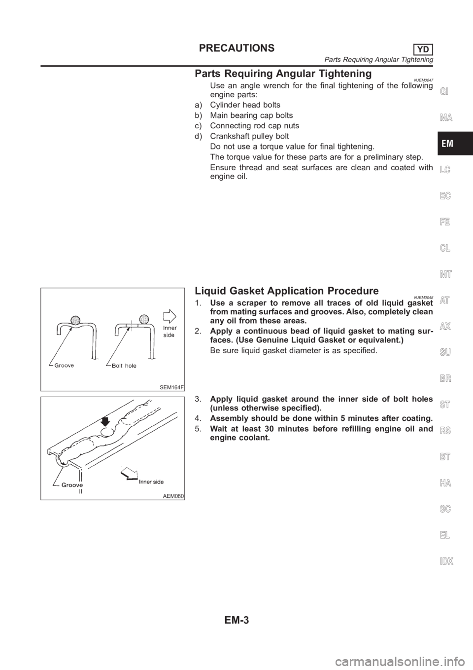
Parts Requiring Angular TighteningNJEM0047Use an angle wrench for the final tightening of the following
engine parts:
a) Cylinder head bolts
b) Main bearing cap bolts
c) Connecting rod cap nuts
d) Crankshaft pulley bolt
Do not use a torque value for final tightening.
The torque value for these parts are for a preliminary step.
Ensure thread and seat surfaces are clean and coated with
engine oil.
SEM164F
Liquid Gasket Application ProcedureNJEM00481.Use a scraper to remove all traces of old liquid gasket
from mating surfaces and grooves. Also, completely clean
any oil from these areas.
2.Apply a continuous bead of liquid gasket to mating sur-
faces. (Use Genuine Liquid Gasket or equivalent.)
Be sure liquid gasket diameter is as specified.
AEM080
3.Apply liquid gasket around the inner side of bolt holes
(unless otherwise specified).
4.Assembly should be done within 5 minutes after coating.
5.Wait at least 30 minutes before refilling engine oil and
engine coolant.
GI
MA
LC
EC
FE
CL
MT
AT
AX
SU
BR
ST
RS
BT
HA
SC
EL
IDX
PRECAUTIONSYD
Parts Requiring Angular Tightening
EM-3
Page 204 of 3189
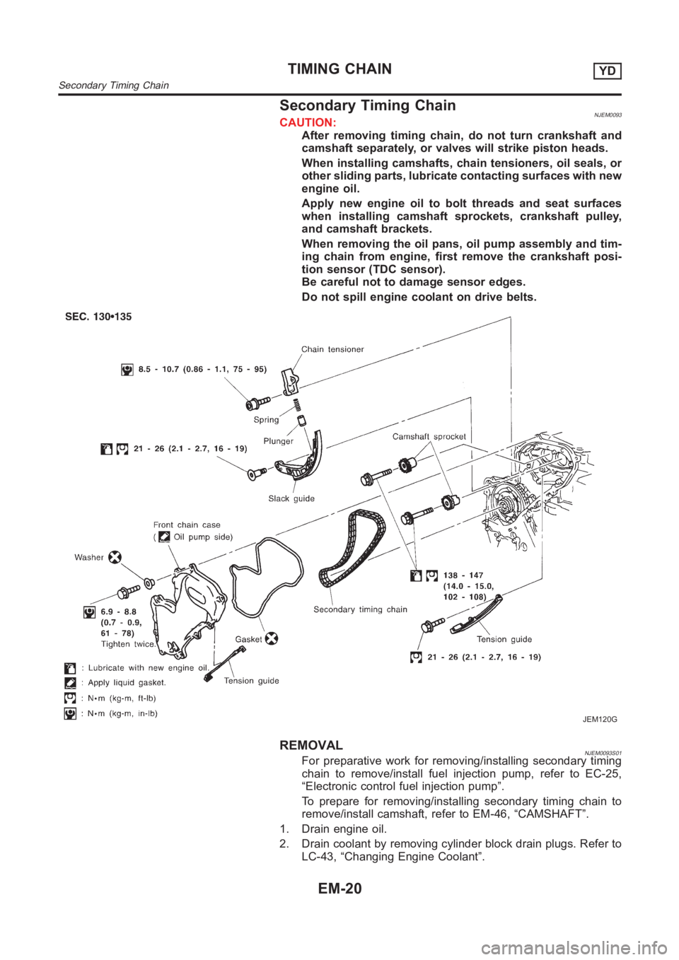
Secondary Timing ChainNJEM0093CAUTION:
After removing timing chain, do not turn crankshaft and
camshaft separately, or valves will strike piston heads.
When installing camshafts, chain tensioners, oil seals, or
other sliding parts, lubricate contacting surfaces with new
engine oil.
Apply new engine oil to bolt threads and seat surfaces
when installing camshaft sprockets, crankshaft pulley,
and camshaft brackets.
When removing the oil pans, oil pump assembly and tim-
ing chain from engine, first remove the crankshaft posi-
tion sensor (TDC sensor).
Be careful not to damage sensor edges.
Do not spill engine coolant on drive belts.
JEM120G
REMOVALNJEM0093S01For preparative work for removing/installing secondary timing
chain to remove/install fuel injection pump, refer to EC-25,
“Electronic control fuel injection pump”.
To prepare for removing/installing secondary timing chain to
remove/install camshaft, refer to EM-46, “CAMSHAFT”.
1. Drain engine oil.
2. Drain coolant by removing cylinder block drain plugs. Refer to
LC-43, “Changing Engine Coolant”.
TIMING CHAINYD
Secondary Timing Chain
EM-20
Page 217 of 3189
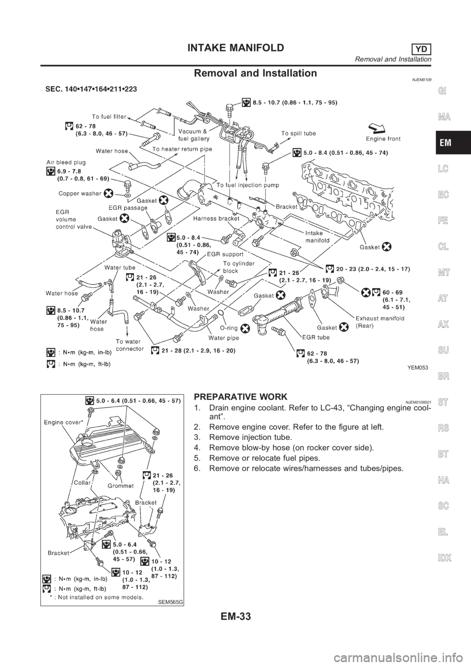
Removal and InstallationNJEM0109
YEM053
SEM565G
PREPARATIVE WORKNJEM0109S011. Drain engine coolant. Refer to LC-43, “Changing engine cool-
ant”.
2. Remove engine cover. Refer to the figure at left.
3. Remove injection tube.
4. Remove blow-by hose (on rocker cover side).
5. Remove or relocate fuel pipes.
6. Remove or relocate wires/harnesses and tubes/pipes.
GI
MA
LC
EC
FE
CL
MT
AT
AX
SU
BR
ST
RS
BT
HA
SC
EL
IDX
INTAKE MANIFOLDYD
Removal and Installation
EM-33
Page 220 of 3189
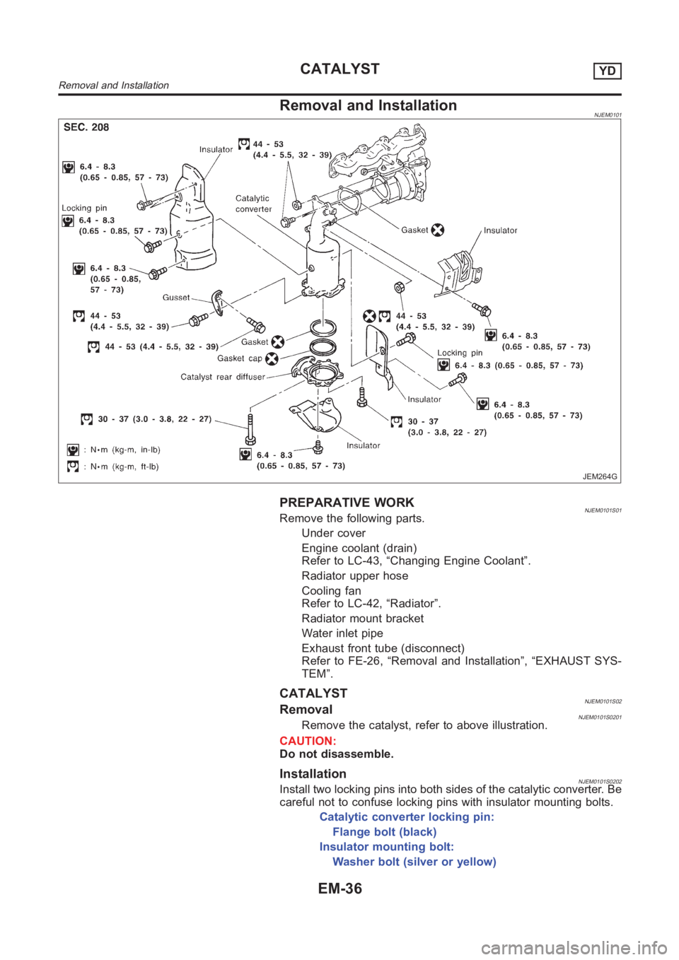
Removal and InstallationNJEM0101
JEM264G
PREPARATIVE WORKNJEM0101S01Remove the following parts.
Under cover
Engine coolant (drain)
Refer to LC-43, “Changing Engine Coolant”.
Radiator upper hose
Cooling fan
Refer to LC-42, “Radiator”.
Radiator mount bracket
Water inlet pipe
Exhaust front tube (disconnect)
Refer to FE-26, “Removal and Installation”, “EXHAUST SYS-
TEM”.
CATALYSTNJEM0101S02RemovalNJEM0101S0201Remove the catalyst, refer to above illustration.
CAUTION:
Do not disassemble.
InstallationNJEM0101S0202Install two locking pins into both sides of the catalytic converter. Be
careful not to confuse locking pins with insulator mounting bolts.
Catalytic converter locking pin:
Flange bolt (black)
Insulator mounting bolt:
Washer bolt (silver or yellow)
CATALYSTYD
Removal and Installation
EM-36
Page 222 of 3189
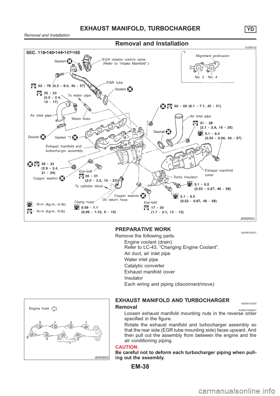
Removal and InstallationNJEM0102
JEM265G
PREPARATIVE WORKNJEM0102S01Remove the following parts.
Engine coolant (drain)
Refer to LC-43, “Changing Engine Coolant”.
Air duct, air inlet pipe
Water inlet pipe
Catalytic converter
Exhaust manifold cover
Insulator
Each wiring and piping (disconnect/move)
JEM266G
EXHAUST MANIFOLD AND TURBOCHARGERNJEM0102S02RemovalNJEM0102S0201Loosen exhaust manifold mounting nuts in the reverse order
specified in the figure.
Rotate the exhaust manifold and turbocharger assembly so
that the rear side (EGR tube mounting side) faces upward. And
then pull out the assembly from between the engine and the
air conditioning piping.
CAUTION:
Be careful not to deform each turbocharger piping when pull-
ing out the assembly.
EXHAUST MANIFOLD, TURBOCHARGERYD
Removal and Installation
EM-38
Page 230 of 3189
CAUTION:
When installing camshafts, chain tensioners, oil seals, or
other sliding parts, lubricate contacting surfaces with new
engine oil.
Apply new engine oil to threads and seat surfaces when
installing cylinder head, camshaft sprocket, crankshaft
pulley, and camshaft bracket.
Attach tags to valve lifters so as not to mix them up.
RemovalNJEM0063PREPARATIVE WORKNJEM0063S011. Drain engine coolant. Refer to LC-43, “Changing Engine Cool-
ant”.
2. Remove exhaust manifold. Refer to EM-38, “Removal”.
3. Remove intake manifold. Refer to EM-34, “Removal”.
Apply paint to camshaft sprockets for alignment during
installation.
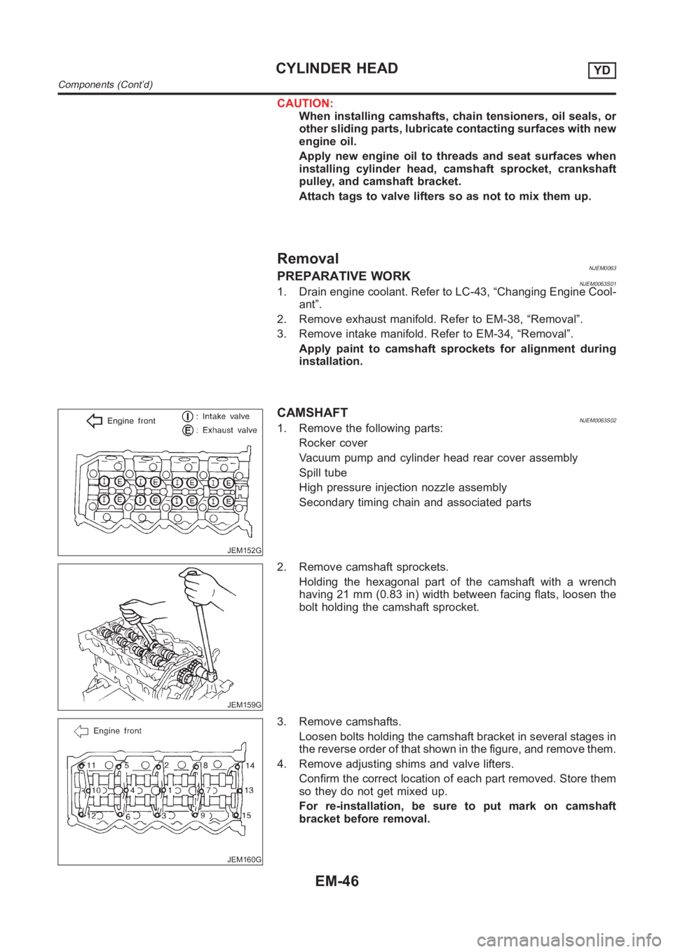
JEM152G
CAMSHAFTNJEM0063S021. Remove the following parts:
Rocker cover
Vacuum pump and cylinder head rear cover assembly
Spill tube
High pressure injection nozzle assembly
Secondary timing chain and associated parts
JEM159G
2. Remove camshaft sprockets.
Holding the hexagonal part of the camshaft with a wrench
having 21 mm (0.83 in) width between facing flats, loosen the
bolt holding the camshaft sprocket.
JEM160G
3. Remove camshafts.
Loosen bolts holding the camshaft bracket in several stages in
the reverse order of that shown in the figure, and remove them.
4. Remove adjusting shims and valve lifters.
Confirm the correct location of each part removed. Store them
so they do not get mixed up.
For re-installation, be sure to put mark on camshaft
bracket before removal.
CYLINDER HEADYD
Components (Cont’d)
EM-46
Page 248 of 3189
crankshaft position sensor (TDC sensor) from the assem-
bly.
Always pay extra attention not to damage edge of crank-
shaft position sensor (TDC sensor) or ring gear teeth.
REMOVALNJEM0069S011. Remove engine undercover, and hood for hoisting.
2. Drain coolant from both cylinder block and radiator. Refer to
LC-43, “Changing Engine Coolant”.
3. Remove the following parts:
Battery
RH and LH front wheels
RH and LH splash covers (combined with undercover)
Auxiliary belts
Alternator
Alternator brackets
Radiator and cooling fan
Engine cover
Air ducts and air cleaner case
LH side of engine room:
4. Disconnect all harnesses and grounds that are connected to
components on vehicle.
5. Disconnect vacuum hose on vacuum pump side.
6. Disconnect fuel feed and fuel return hoses on engine side.
Immediately put blind plugs into the openings to prevent
fuel from flowing out.
7. Disconnect heater hose. Plug opening of hose to prevent cool-
ant from flowing out.
RH side of engine room:
8. Remove air conditioner compressor from brackets and move
it toward vehicle side. Secure compressor on vehicle side with
rope.
Vehicle underside:
9. Remove exhaust front tube.
10. Disconnect two hoses from power steering pump and plug to
stop fluid.
11. Remove M/T control rod and support rod.
12. Remove ABS wheel sensor, and temporarily hang brake cali-
per with rope on vehicle side.
13. Remove RH and LH drive shafts.
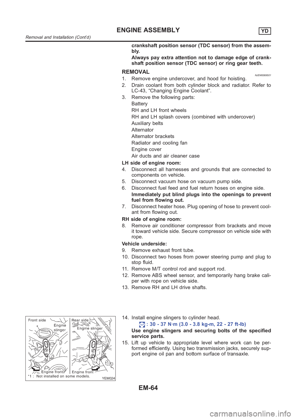
YEM024
14. Install engine slingers to cylinder head.
: 30 - 37 N·m (3.0 - 3.8 kg-m, 22 - 27 ft-lb)
Use engine slingers and securing bolts of the specified
service parts.
15. Lift up vehicle to appropriate level where work can be per-
formed efficiently. Using two transmission jacks, securely sup-
port engine oil pan and bottom surface of transaxle.
ENGINE ASSEMBLYYD
Removal and Installation (Cont’d)
EM-64
Page 252 of 3189
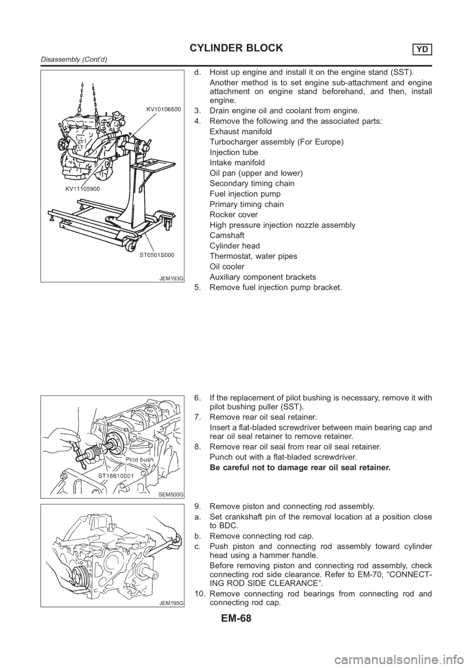
JEM193G
d. Hoist up engine and install it on the engine stand (SST).
Another method is to set engine sub-attachment and engine
attachment on engine stand beforehand, and then, install
engine.
3. Drain engine oil and coolant from engine.
4. Remove the following and the associated parts:
Exhaust manifold
Turbocharger assembly (For Europe)
Injection tube
Intake manifold
Oil pan (upper and lower)
Secondary timing chain
Fuel injection pump
Primary timing chain
Rocker cover
High pressure injection nozzle assembly
Camshaft
Cylinder head
Thermostat, water pipes
Oil cooler
Auxiliary component brackets
5. Remove fuel injection pump bracket.
SEM500G
6. If the replacement of pilot bushing is necessary, remove it with
pilot bushing puller (SST).
7. Remove rear oil seal retainer.
Insert a flat-bladed screwdriver between main bearing cap and
rear oil seal retainer to remove retainer.
8. Remove rear oil seal from rear oil seal retainer.
Punch out with a flat-bladed screwdriver.
Be careful not to damage rear oil seal retainer.
JEM195G
9. Remove piston and connecting rod assembly.
a. Set crankshaft pin of the removal location at a position close
to BDC.
b. Remove connecting rod cap.
c. Push piston and connecting rod assembly toward cylinder
head using a hammer handle.
Before removing piston and connecting rod assembly, check
connecting rod side clearance. Refer to EM-70, “CONNECT-
ING ROD SIDE CLEARANCE”.
10. Remove connecting rod bearings from connecting rod and
connecting rod cap.
CYLINDER BLOCKYD
Disassembly (Cont’d)
EM-68