NISSAN ALMERA N16 2003 Electronic Repair Manual
Manufacturer: NISSAN, Model Year: 2003, Model line: ALMERA N16, Model: NISSAN ALMERA N16 2003Pages: 3189, PDF Size: 54.76 MB
Page 2021 of 3189
TROUBLE DIAGNOSIS
ATC-41
C
D
E
F
G
H
I
K
L
MA
B
AT C
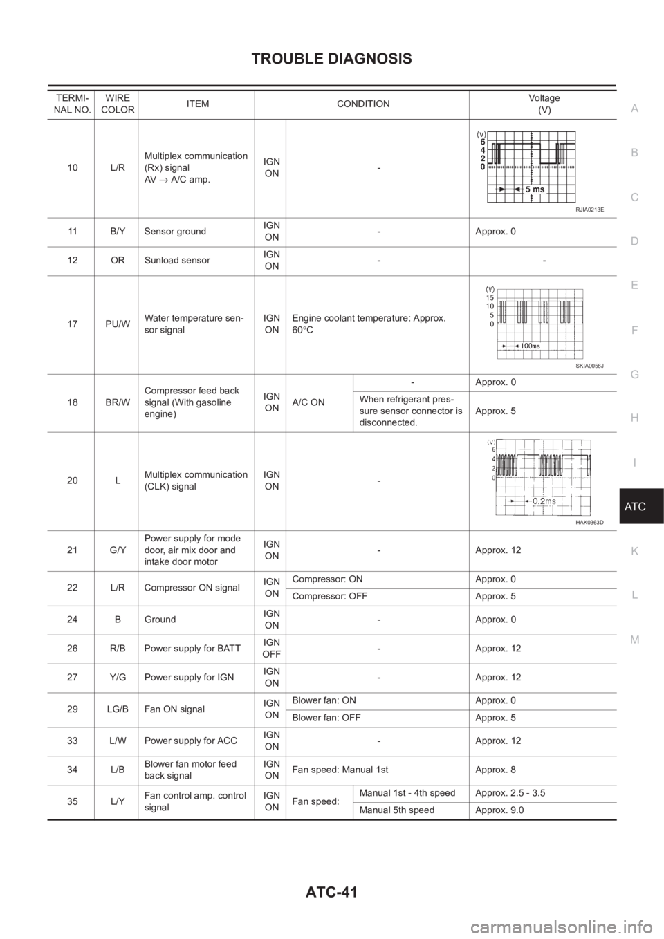
10 L/RMultiplex communication
(Rx) signal
AV → A/C amp.IGN
ON-
11 B/Y Sensor ground IGN
ON-Approx. 0
12 OR Sunload sensorIGN
ON--
17 PU/WWater temperature sen-
sor signalIGN
ONEngine coolant temperature: Approx.
60°C
18 BR/WCompressor feed back
signal (With gasoline
engine)IGN
ONA/C ON-Approx. 0
When refrigerant pres-
sure sensor connector is
disconnected.Approx. 5
20 LMultiplex communication
(CLK) signalIGN
ON-
21 G/YPower supply for mode
door, air mix door and
intake door motorIGN
ON-Approx. 12
22 L/R Compressor ON signalIGN
ONCompressor: ON Approx. 0
Compressor: OFF Approx. 5
24 B GroundIGN
ON-Approx. 0
26 R/B Power supply for BATTIGN
OFF-Approx. 12
27 Y/G Power supply for IGNIGN
ON-Approx. 12
29 LG/B Fan ON signalIGN
ONBlower fan: ON Approx. 0
Blower fan: OFF Approx. 5
33 L/W Power supply for ACCIGN
ON-Approx. 12
34 L/BBlower fan motor feed
back signalIGN
ONFan speed: Manual 1st Approx. 8
35 L/YFan control amp. control
signalIGN
ONFan speed:Manual 1st - 4th speed Approx. 2.5 - 3.5
Manual 5th speed Approx. 9.0 TERMI-
NAL NO.WIRE
COLORITEM CONDITIONVo lta g e
(V)
RJIA0213E
SKIA0056J
HAK0363D
Page 2022 of 3189
ATC-42
TROUBLE DIAGNOSIS
Self-diagnosis Function
EJS001ZH
DESCRIPTION
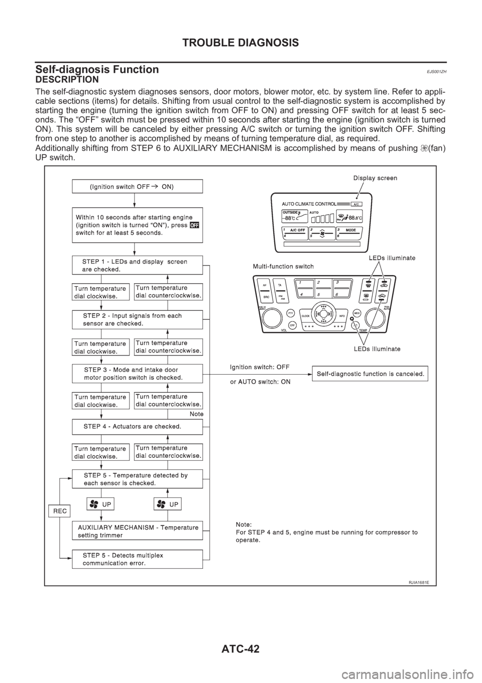
The self-diagnostic system diagnoses sensors, door motors, blower motor, etc. by system line. Refer to appli-
cable sections (items) for details. Shifting from usual control to the self-diagnostic system is accomplished by
starting the engine (turning the ignition switch from OFF to ON) and pressing OFF switch for at least 5 sec-
onds. The “OFF” switch must be pressed within 10 seconds after starting the engine (ignition switch is turned
ON). This system will be canceled by either pressing A/C switch or turning the ignition switch OFF. Shifting
from one step to another is accomplished by means of turning temperature dial, as required.
Additionally shifting from STEP 6 to AUXILIARY MECHANISM is accomplished by means of pushing (fan)
UP switch.
RJIA1681E
Page 2023 of 3189
TROUBLE DIAGNOSIS
ATC-43
C
D
E
F
G
H
I
K
L
MA
B
AT C
FUNCTION CONFIRMATION PROCEDURE
1.SET IN SELF-DIAGNOSTIC MODE
Method 1 (Without navigation system, or with navigation system)
1. Turn ignition switch to ON.
2. Within 10 seconds after starting engine (ignition switch is turned ON.), press and hold OFF switch for at
least 5 seconds.
3. The self-diagnosis (step 1) should start.
Method 2 (Only with navigation system)
1. Turn OFF the audio system.
2. While pressing “Vehicle Information” switch, turn audio switch (volume adjustment dial) by at least 30
notches.
3. Trouble diagnosis initial screen appears. Using joystick, select “Confirmation and Adjustment”. And press
“Confirm”.
4. Confirmation and adjustment initial screen appears. Using joystick, select “Air-conditioner trouble diagno-
sis”, and press “Confirm” to start self-diagnosis (step 1).
CAUTION:
If battery voltage drops below 12V during step diagnosis 3, actuator speed becomes slower and as a
result, the system may generate an error even when operation is normal. To avoid this, start engine
before performing this diagnosis.
>> GO TO 2.
Page 2024 of 3189
ATC-44
TROUBLE DIAGNOSIS
2. STEP 1 - LEDS AND DISPLAY ARE CHECKED
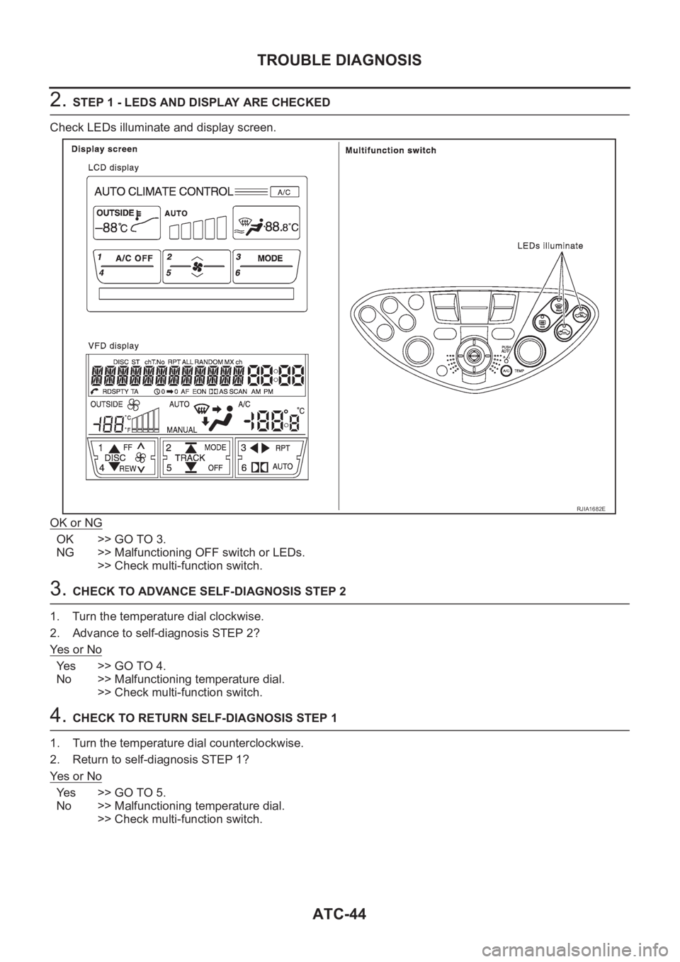
Check LEDs illuminate and display screen.
OK or NG
OK >> GO TO 3.
NG >> Malfunctioning OFF switch or LEDs.
>> Check multi-function switch.
3. CHECK TO ADVANCE SELF-DIAGNOSIS STEP 2
1. Turn the temperature dial clockwise.
2. Advance to self-diagnosis STEP 2?
Ye s o r N o
Yes >> GO TO 4.
No >> Malfunctioning temperature dial.
>> Check multi-function switch.
4. CHECK TO RETURN SELF-DIAGNOSIS STEP 1
1. Turn the temperature dial counterclockwise.
2. Return to self-diagnosis STEP 1?
Ye s o r N o
Yes >> GO TO 5.
No >> Malfunctioning temperature dial.
>> Check multi-function switch.
RJIA1682E
Page 2025 of 3189
TROUBLE DIAGNOSIS
ATC-45
C
D
E
F
G
H
I
K
L
MA
B
AT C
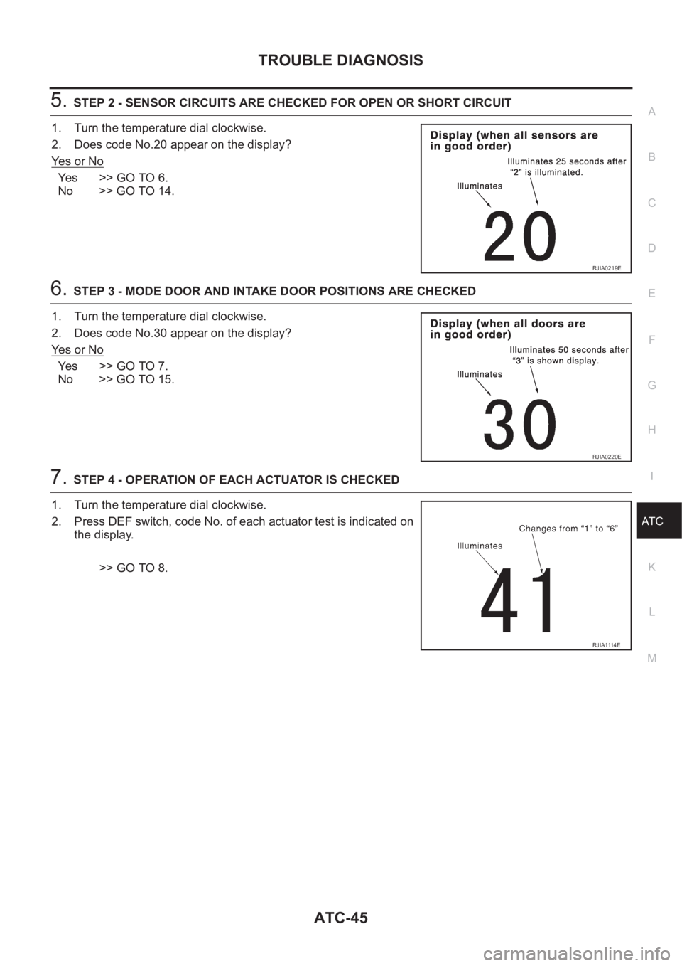
5.STEP 2 - SENSOR CIRCUITS ARE CHECKED FOR OPEN OR SHORT CIRCUIT
1. Turn the temperature dial clockwise.
2. Does code No.20 appear on the display?
Ye s o r N o
Ye s > > G O T O 6 .
No >> GO TO 14.
6.STEP 3 - MODE DOOR AND INTAKE DOOR POSITIONS ARE CHECKED
1. Turn the temperature dial clockwise.
2. Does code No.30 appear on the display?
Ye s o r N o
Ye s > > G O T O 7 .
No >> GO TO 15.
7.STEP 4 - OPERATION OF EACH ACTUATOR IS CHECKED
1. Turn the temperature dial clockwise.
2. Press DEF switch, code No. of each actuator test is indicated on
the display.
>> GO TO 8.
RJIA0219E
RJIA0220E
RJIA1114E
Page 2026 of 3189
ATC-46
TROUBLE DIAGNOSIS
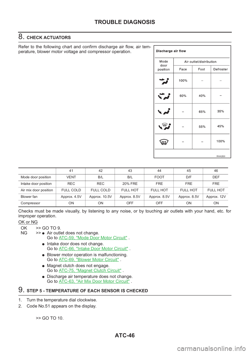
8. CHECK ACTUATORS
Refer to the following chart and confirm discharge air flow, air tem-
perature, blower motor voltage and compressor operation.
Checks must be made visually, by listening to any noise, or by touching air outlets with your hand, etc. for
improper operation.
OK or NG
OK >> GO TO 9.
NG >>
●Air outlet does not change.
Go to AT C - 5 9 , "
Mode Door Motor Circuit" .
●Intake door does not change.
Go to AT C - 6 6 , "
Intake Door Motor Circuit" .
●Blower motor operation is malfunctioning.
Go to AT C - 6 9 , "
Blower Motor Circuit" .
●Magnet clutch does not engage.
Go to AT C - 7 5 , "
Magnet Clutch Circuit" .
●Discharge air temperature does not change.
Go to AT C - 6 3 , "
Air Mix Door Motor Circuit" .
9. STEP 5 - TEMPERATURE OF EACH SENSOR IS CHECKED
1. Turn the temperature dial clockwise.
2. Code No.51 appears on the display.
>> GO TO 10.
RHA280I
41 42 43 44 45 46
Mode door position VENT B/L B/L FOOT D/F DEF
Intake door position REC REC 20% FRE FRE FRE FRE
Air mix door position FULL COLD FULL COLD FULL HOT FULL HOT FULL HOTFULL HOT
Blower fan Approx. 4.5V Approx. 10.5V Approx. 8.5V Approx. 8.5V Approx. 8.5V Approx. 12V
Compressor ON ON OFF OFF ON ON
Page 2027 of 3189
TROUBLE DIAGNOSIS
ATC-47
C
D
E
F
G
H
I
K
L
MA
B
AT C
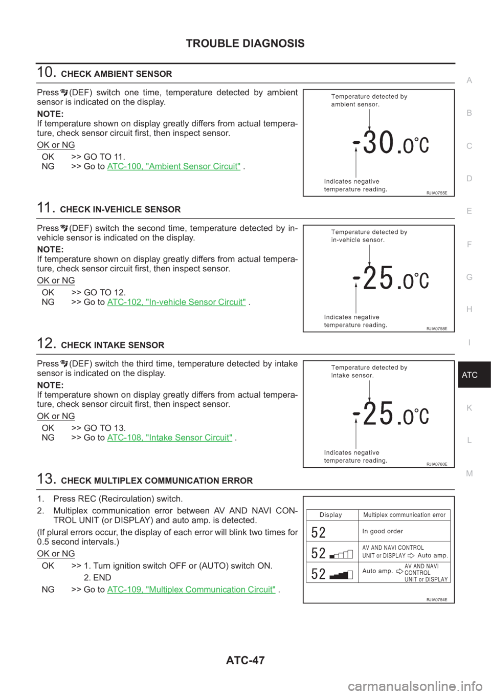
10.CHECK AMBIENT SENSOR
Press (DEF) switch one time, temperature detected by ambient
sensor is indicated on the display.
NOTE:
If temperature shown on display greatly differs from actual tempera-
ture, check sensor circuit first, then inspect sensor.
OK or NG
OK >> GO TO 11.
NG >> Go to ATC-100, "
Ambient Sensor Circuit" .
11 . CHECK IN-VEHICLE SENSOR
Press (DEF) switch the second time, temperature detected by in-
vehicle sensor is indicated on the display.
NOTE:
If temperature shown on display greatly differs from actual tempera-
ture, check sensor circuit first, then inspect sensor.
OK or NG
OK >> GO TO 12.
NG >> Go to ATC-102, "
In-vehicle Sensor Circuit" .
12.CHECK INTAKE SENSOR
Press (DEF) switch the third time, temperature detected by intake
sensor is indicated on the display.
NOTE:
If temperature shown on display greatly differs from actual tempera-
ture, check sensor circuit first, then inspect sensor.
OK or NG
OK >> GO TO 13.
NG >> Go to ATC-108, "
Intake Sensor Circuit" .
13.CHECK MULTIPLEX COMMUNICATION ERROR
1. Press REC (Recirculation) switch.
2. Multiplex communication error between AV AND NAVI CON-
TROL UNIT (or DISPLAY) and auto amp. is detected.
(If plural errors occur, the display of each error will blink two times for
0.5 second intervals.)
OK or NG
OK >> 1. Turn ignition switch OFF or (AUTO) switch ON.
2. END
NG >> Go to ATC-109, "
Multiplex Communication Circuit" .
RJIA0755E
RJIA0758E
RJIA0760E
RJIA0754E
Page 2028 of 3189
ATC-48
TROUBLE DIAGNOSIS
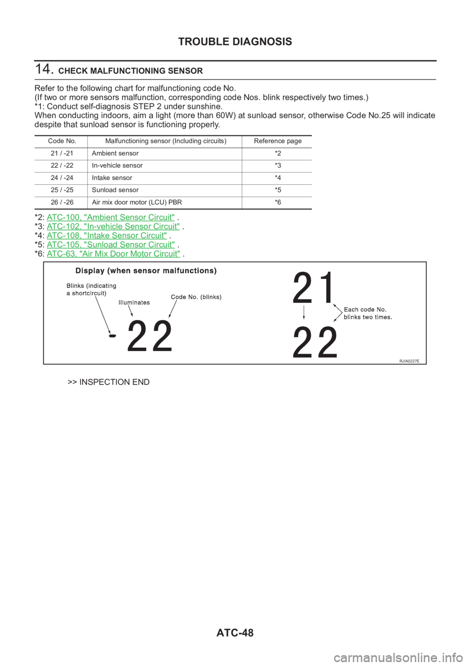
14. CHECK MALFUNCTIONING SENSOR
Refer to the following chart for malfunctioning code No.
(If two or more sensors malfunction, corresponding code Nos. blink respectively two times.)
*1: Conduct self-diagnosis STEP 2 under sunshine.
When conducting indoors, aim a light (more than 60W) at sunload sensor, otherwise Code No.25 will indicate
despite that sunload sensor is functioning properly.
*2: ATC-100, "
Ambient Sensor Circuit" .
*3: ATC-102, "
In-vehicle Sensor Circuit" .
*4: ATC-108, "
Intake Sensor Circuit" .
*5: ATC-105, "
Sunload Sensor Circuit" .
*6: AT C - 6 3 , "
Air Mix Door Motor Circuit" .
>> INSPECTION END
Code No. Malfunctioning sensor (Including circuits) Reference page
21 / -21 Ambient sensor *2
22 / -22 In-vehicle sensor *3
24 / -24 Intake sensor *4
25 / -25 Sunload sensor *5
26 / -26 Air mix door motor (LCU) PBR *6
RJIA0227E
Page 2029 of 3189
TROUBLE DIAGNOSIS
ATC-49
C
D
E
F
G
H
I
K
L
MA
B
AT C
15.CHECK MALFUNCTIONING DOOR MOTOR POSITION SWITCH
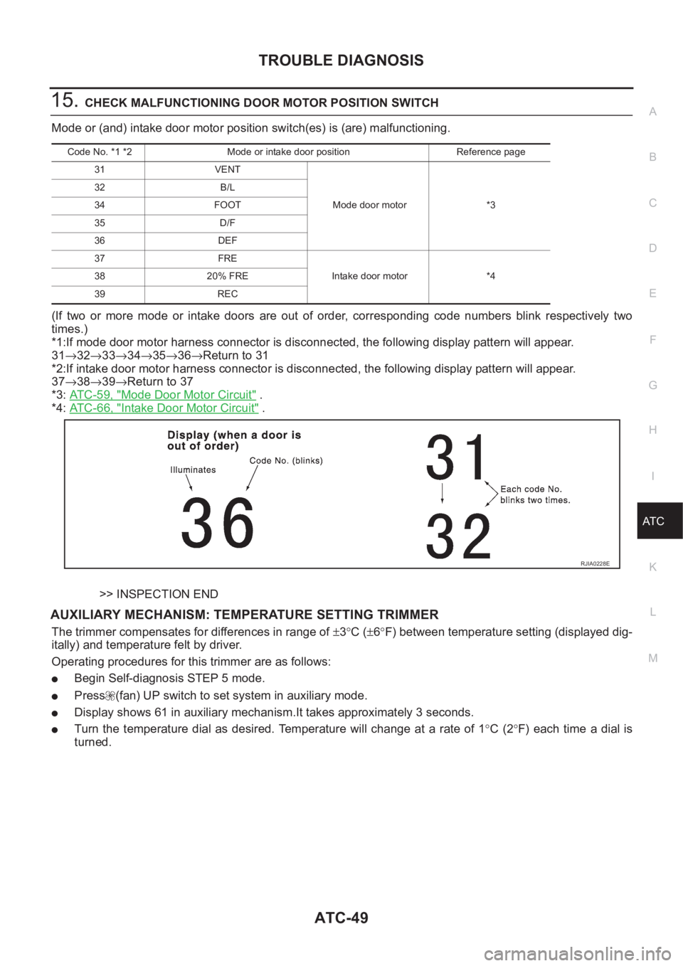
Mode or (and) intake door motor position switch(es) is (are) malfunctioning.
(If two or more mode or intake doors are out of order, corresponding code numbers blink respectively two
times.)
*1:If mode door motor harness connector is disconnected, the following display pattern will appear.
31→32→33→34→35→36→Return to 31
*2:If intake door motor harness connector is disconnected, the following display pattern will appear.
37→38→39→Return to 37
*3: AT C - 5 9 , "
Mode Door Motor Circuit" .
*4: AT C - 6 6 , "
Intake Door Motor Circuit" .
>> INSPECTION END
AUXILIARY MECHANISM: TEMPERATURE SETTING TRIMMER
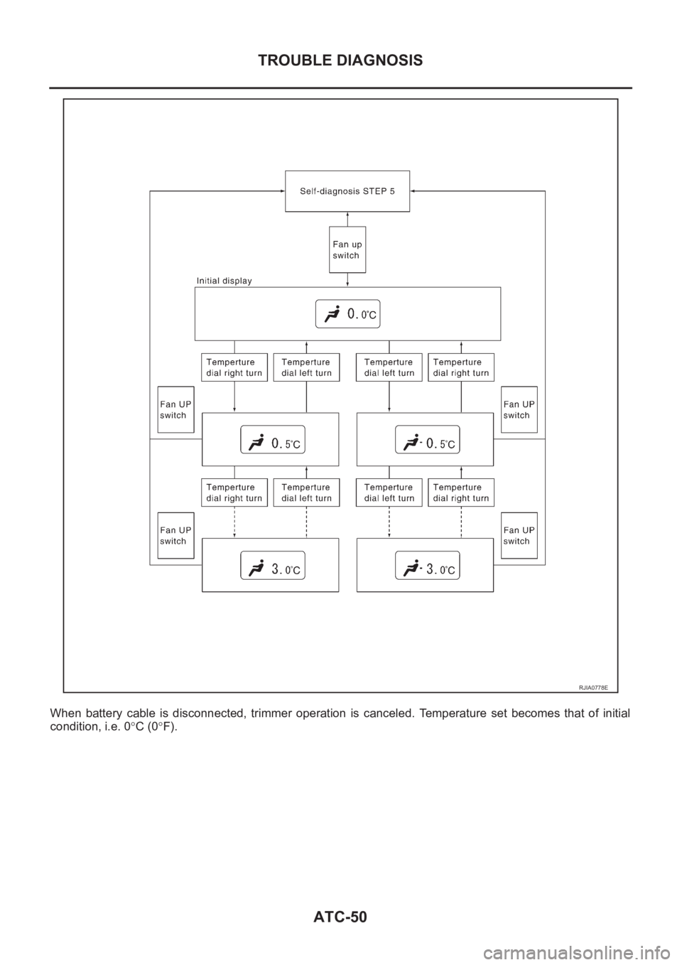
The trimmer compensates for differences in range of ±3°C (±6°F) between temperature setting (displayed dig-
itally) and temperature felt by driver.
Operating procedures for this trimmer are as follows:
●Begin Self-diagnosis STEP 5 mode.
●Press (fan) UP switch to set system in auxiliary mode.
●Display shows 61 in auxiliary mechanism.It takes approximately 3 seconds.
●Turn the temperature dial as desired. Temperature will change at a rate of 1°C (2°F) each time a dial is
turned.
Code No. *1 *2 Mode or intake door position Reference page
31 VENT
Mode door motor *3 32 B/L
34 FOOT
35 D/F
36 DEF
37 FRE
Intake door motor *4 38 20% FRE
39 REC
RJIA0228E
Page 2030 of 3189
ATC-50
TROUBLE DIAGNOSIS
When battery cable is disconnected, trimmer operation is canceled. Temperature set becomes that of initial
condition, i.e. 0°C (0°F).
RJIA0778E