Time NISSAN ALMERA N16 2003 Electronic Repair Manual
[x] Cancel search | Manufacturer: NISSAN, Model Year: 2003, Model line: ALMERA N16, Model: NISSAN ALMERA N16 2003Pages: 3189, PDF Size: 54.76 MB
Page 2 of 3189

FOREWORD
This manual contains maintenance and repair procedures for NISSAN
ALMERA, model N16 series.
In order to assure your safety and the efficient functioning of the vehicle,
this manual should be read thoroughly. It is especially important that the
PRECAUTIONS in the GI section be completely understood before starting
any repair task.
All information in this manual is based on the latest product information
at the time of publication. The right is reserved to make changes in speci-
fications and methods at any time without notice.
IMPORTANT SAFETY NOTICE
The proper performance of service is essential for both the safety of the
technician and the efficient functioning of the vehicle.
The service methods in this Service Manual are described in such a man-
ner that the service may be performed safely and accurately.
Service varies with the procedures used, the skills of the technician and the
tools and parts available. Accordingly, anyone using service procedures,
tools or parts which are not specifically recommended by NISSAN must
first completely satisfy himself that neither his safety nor the vehicle’s
safety will be jeopardized by the service method selected.
NISSAN EUROPE S.A.S.
Service Engineering Section
Paris, France
Page 6 of 3189
The security indicator is located on the combi meter. The indicator
blinks when the ignition switch is in “OFF” or “ACC” position.
Therefore, NATS warns outsiders that the vehicle is equipped with
the anti-theft system.
When NATS detects trouble, the security indicator lamp lights
up while ignition switch is in “ON” position.
This lighting up indicates that the anti-theft is not functioning,
so prompt service is required.
When servicing NATS (trouble diagnoses, system initialization
and additional registration of other NATS ignition key IDs),
CONSULT-II hardware and CONSULT-II NATS software is
necessary.
Regarding the procedures of NATS initialization and NATS
ignition key ID registration, refer to CONSULT-II operation
manual, NATS.
Therefore, CONSULT-II NATS software (program card and
operation manual) must be kept strictly confidential to main-
tain the integrity of the anti-theft function.
When servicing NATS (trouble diagnoses, system initialization
and additional registration of other NATS ignition key IDs), it
may be necessary to re-register original key identification.
Therefore, be sure to receive all keys from vehicle owner. A
maximum of five key IDs can be registered into NATS.
When failing to start the engine first time using the key of
NATS, start as follows.
a) Leave the ignition key in “ON” position for approximately 5
seconds.
b) Turn ignition key to “OFF” or “LOCK” position and wait approxi-
mately 5 seconds.
c) Repeat step 1 and 2 again.
d) Restart the engine while keeping the key separate from any
others on key-chain.
SGI285
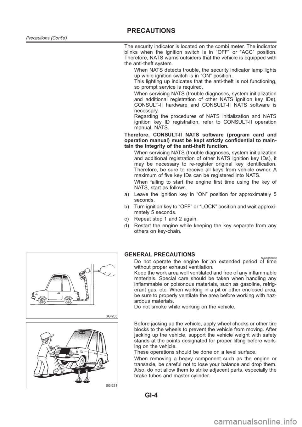
GENERAL PRECAUTIONSNJGI0001S03Do not operate the engine for an extended period of time
without proper exhaust ventilation.
Keep the work area well ventilated and free of any inflammable
materials. Special care should be taken when handling any
inflammable or poisonous materials, such as gasoline, refrig-
erant gas, etc. When working in a pit or other enclosed area,
be sure to properly ventilate the area before working with haz-
ardous materials.
Do not smoke while working on the vehicle.
SGI231
Before jacking up the vehicle, apply wheel chocks or other tire
blocks to the wheels to prevent the vehicle from moving. After
jacking up the vehicle, support the vehicle weight with safety
stands at the points designated for proper lifting before work-
ing on the vehicle.
These operations should be done on a level surface.
When removing a heavy component such as the engine or
transaxle, be careful not to lose your balance and drop them.
Also, do not allow them to strike adjacent parts, especially the
brake tubes and master cylinder.
PRECAUTIONS
Precautions (Cont’d)
GI-4
Page 11 of 3189

fuels in your diesel engine. The use of those can cause
engine damage.
Do not use summer fuel at temperatures below −7°C
(20°F). The cold temperatures will cause wax to form in the
fuel. As a result, it may prevent the engine from running
smoothly.
Do not add gasoline or other alternate fuels to diesel fuel.
PRECAUTIONS FOR AIR CONDITIONINGNJGI0001S09Use an approved refrigerant recovery unit any time the air condi-
tioning system must be discharged. Refer to HA-77 (Manual) or
ATC-132 (Auto), “HFC-134a (R-134a) Service Procedure” for spe-
cific instructions.
MA
EM
LC
EC
FE
CL
MT
AT
AX
SU
BR
ST
RS
BT
HA
SC
EL
IDX
PRECAUTIONS
Precautions (Cont’d)
GI-9
Page 24 of 3189

NJGI0005
Work FlowNJGI0005S01
SGI838
STEP DESCRIPTION
STEP 1 Get detailed information about the conditions and the environment when the incident occurred.
The following are key pieces of information required to make a good analysis:
WHATVehicle Model, Engine, Transmission and the System (i.e. Radio).
WHENDate, Time of Day, Weather Conditions, Frequency.
WHERERoad Conditions, Altitude and Traffic Situation.
HOWSystem Symptoms, Operating Conditions (Other Components Interaction).
Service History and if any After Market Accessories have been installed.
STEP 2 Operate the system, road test if necessary.
Verify the parameter of the incident.
If the problem can not be duplicated, refer to “Incident Simulation Tests”next page.
STEP 3 Get the proper diagnoses materials together including:
POWER SUPPLY ROUTING
System Operation Descriptions
Applicable Service Manual Sections
Check for any Service Bulletin.
Identify where to begin diagnoses based upon your knowledge of the system operation and the cus-
tomer comments.
STEP 4 Inspect the system for mechanical binding, loose connectors or wiring damage.
Determine which circuits and components are involved and diagnose using the Power Supply Routing
and Harness Layouts.
STEP 5 Repair or replace the incident circuit or component.
STEP 6 Operate the system in all modes. Verify the system works properly under all conditions. Make sure you
have not inadvertently created a new incident during your diagnoses or repair steps.
HOW TO PERFORM EFFICIENT DIAGNOSES FOR AN ELECTRICAL INCIDENT
Work Flow
GI-22
Page 25 of 3189
Incident Simulation TestsNJGI0005S02INTRODUCTIONNJGI0005S0201Sometimes the symptom is not present when the vehicle is brought
in for service. If possible, re-create the conditions present at the
time of the incident. Doing so may help avoid a No Trouble Found
Diagnoses. The following section illustrates ways to simulate the
conditions/environment under which the owner experiences an
electrical incident.
The section is broken into the six following topics:
Vehicle vibration
Heat sensitive
Freezing
Water intrusion
Electrical load
Cold or hot start up
Get a thorough description of the incident from the customer. It is
important for simulating the conditions of the problem.
VEHICLE VIBRATIONNJGI0005S0202The problem may occur or become worse while driving on a rough
road or when engine is vibrating (idle with A/C on). In such a case,
you will want to check for a vibration related condition. Refer to the
illustration below.
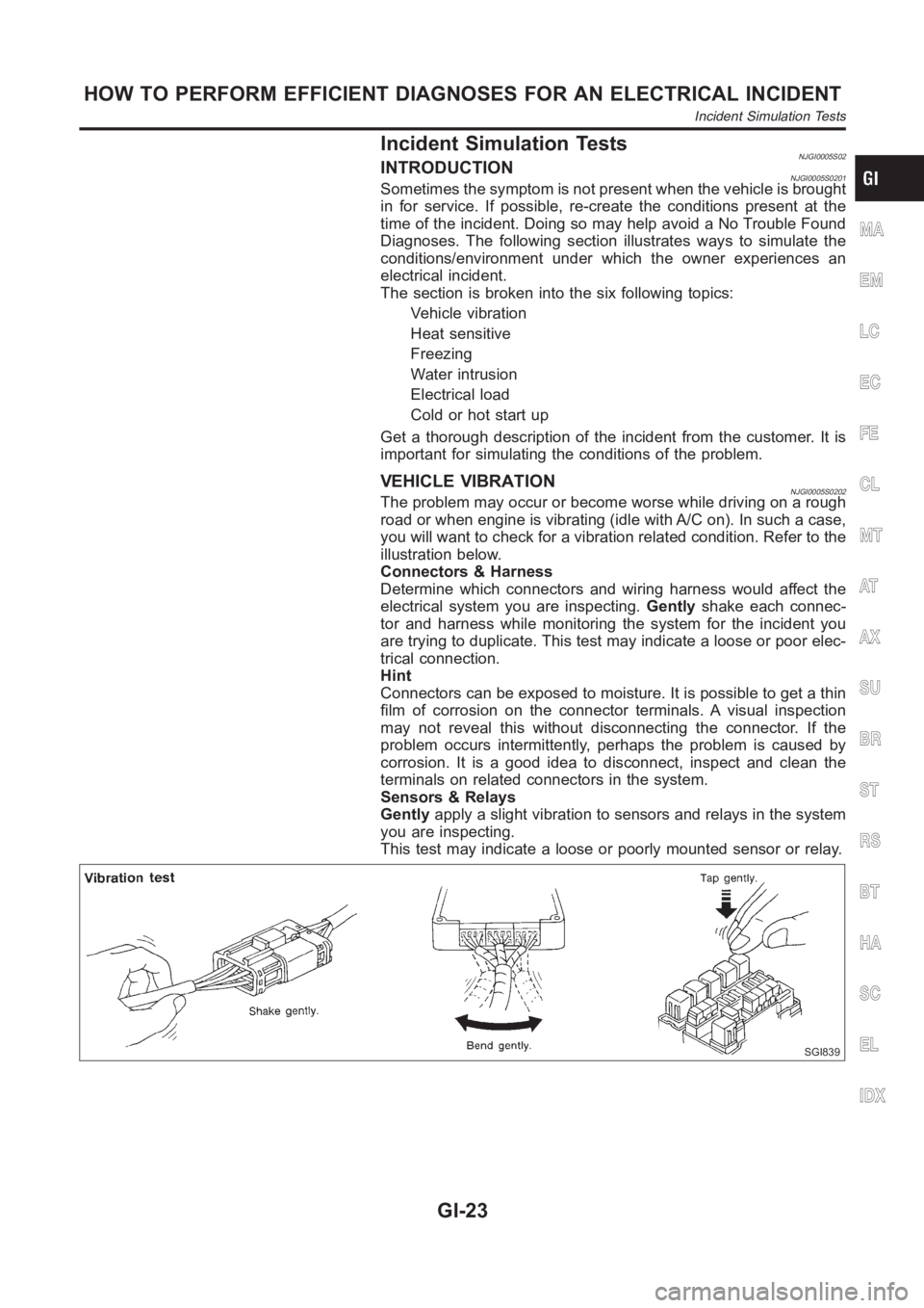
Connectors & Harness
Determine which connectors and wiring harness would affect the
electrical system you are inspecting.Gentlyshake each connec-
tor and harness while monitoring the system for the incident you
are trying to duplicate. This test may indicate a loose or poor elec-
trical connection.
Hint
Connectors can be exposed to moisture. It is possible to get a thin
film of corrosion on the connector terminals. A visual inspection
may not reveal this without disconnecting the connector. If the
problem occurs intermittently, perhaps the problem is caused by
corrosion. It is a good idea to disconnect, inspect and clean the
terminals on related connectors in the system.
Sensors & Relays
Gentlyapply a slight vibration to sensors and relays in the system
you are inspecting.
This test may indicate a loose or poorly mounted sensor or relay.
SGI839
MA
EM
LC
EC
FE
CL
MT
AT
AX
SU
BR
ST
RS
BT
HA
SC
EL
IDX
HOW TO PERFORM EFFICIENT DIAGNOSES FOR AN ELECTRICAL INCIDENT
Incident Simulation Tests
GI-23
Page 26 of 3189

Engine Compartment
There are several reasons a vehicle or engine vibration could
cause an electrical complaint. Some of the things to check for are:
Connectors not fully seated.
Wiring harness not long enough and is being stressed due to
engine vibrations or rocking.
Wires laying across brackets or moving components.
Loose, dirty or corroded ground wires.
Wires routed too close to hot components.
To inspect components under the hood, start by verifying the integ-
rity of ground connections. (Refer to GROUND INSPECTION
described later.) First check that the system is properly grounded.
Then check for loose connection bygently shakingthe wiring or
components as previously explained. Using the wiring diagrams
inspect the wiring for continuity.
Behind The Instrument Panel
An improperly routed or improperly clamped harness can become
pinched during accessory installation. Vehicle vibration can aggra-
vate a harness which is routed along a bracket or near a screw.
Under Seating Areas
An unclamped or loose harness can cause wiring to be pinched by
seat components (such as slide guides) during vehicle vibration. If
the wiring runs under seating areas, inspect wire routing for pos-
sible damage or pinching.
SGI842
HEAT SENSITIVENJGI0005S0203The owner’s problem may occur during hot weather or after car has
sat for a short time. In such cases you will want to check for a heat
sensitive condition.
To determine if an electrical component is heat sensitive, heat the
component with a heat gun or equivalent.
Do not heat components above 60°C (140°F).If incident occurs
while heating the unit, either replace or properly insulate the com-
ponent.
SGI843
FREEZINGNJGI0005S0204The customer may indicate the incident goes away after the car
warms up (winter time). The cause could be related to water freez-
ing somewhere in the wiring/electrical system.
There are two methods to check for this. The first is to arrange for
the owner to leave his car overnight. Make sure it will get cold
enough to demonstrate his complaint. Leave the car parked out-
side overnight. In the morning, do a quick and thorough diagnoses
of those electrical components which could be affected.
HOW TO PERFORM EFFICIENT DIAGNOSES FOR AN ELECTRICAL INCIDENT
Incident Simulation Tests (Cont’d)
GI-24
Page 28 of 3189
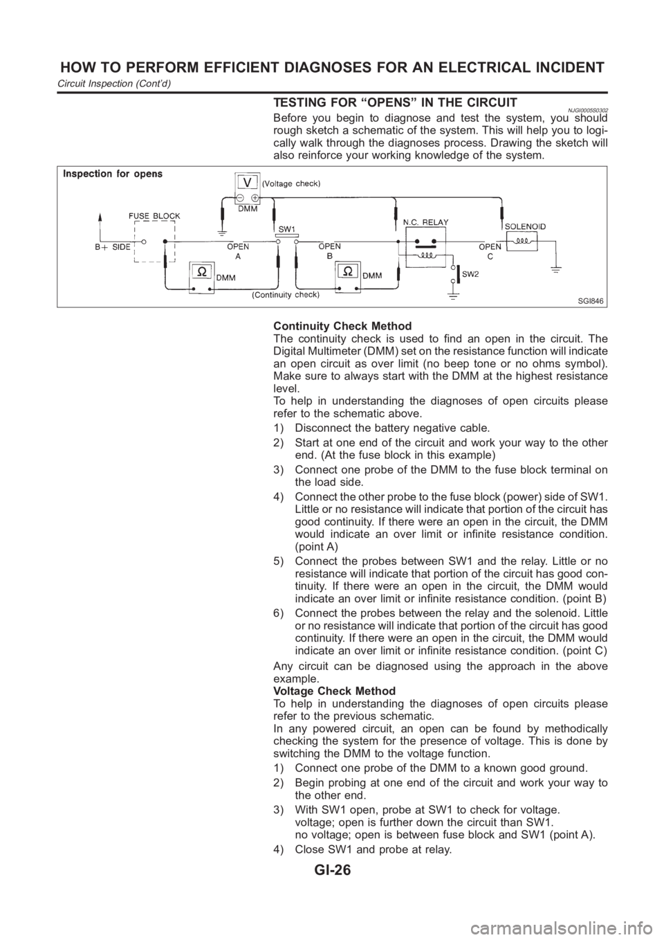
TESTING FOR “OPENS” IN THE CIRCUITNJGI0005S0302Before you begin to diagnose and test the system, you should
rough sketch a schematic of the system. This will help you to logi-
cally walk through the diagnoses process. Drawing the sketch will
also reinforce your working knowledge of the system.
SGI846
Continuity Check Method
The continuity check is used to find an open in the circuit. The
Digital Multimeter (DMM) set on the resistance function will indicate
an open circuit as over limit (no beep tone or no ohms symbol).
Make sure to always start with the DMM at the highest resistance
level.
To help in understanding the diagnoses of open circuits please
refer to the schematic above.
1) Disconnect the battery negative cable.
2) Start at one end of the circuit and work your way to the other
end. (At the fuse block in this example)
3) Connect one probe of the DMM to the fuse block terminal on
the load side.
4) Connect the other probe to the fuse block (power) side of SW1.
Little or no resistance will indicate that portion of the circuit has
good continuity. If there were an open in the circuit, the DMM
would indicate an over limit or infinite resistance condition.
(point A)
5) Connect the probes between SW1 and the relay. Little or no
resistance will indicate that portion of the circuit has good con-
tinuity. If there were an open in the circuit, the DMM would
indicate an over limit or infinite resistance condition. (point B)
6) Connect the probes between the relay and the solenoid. Little
or no resistance will indicate that portion of the circuit has good
continuity. If there were an open in the circuit, the DMM would
indicate an over limit or infinite resistance condition. (point C)
Any circuit can be diagnosed using the approach in the above
example.
Voltage Check Method
To help in understanding the diagnoses of open circuits please
refer to the previous schematic.
In any powered circuit, an open can be found by methodically
checking the system for the presence of voltage. This is done by
switching the DMM to the voltage function.
1) Connect one probe of the DMM to a known good ground.
2) Begin probing at one end of the circuit and work your way to
the other end.
3) With SW1 open, probe at SW1 to check for voltage.
voltage; open is further down the circuit than SW1.
no voltage; open is between fuse block and SW1 (point A).
4) Close SW1 and probe at relay.
HOW TO PERFORM EFFICIENT DIAGNOSES FOR AN ELECTRICAL INCIDENT
Circuit Inspection (Cont’d)
GI-26
Page 38 of 3189
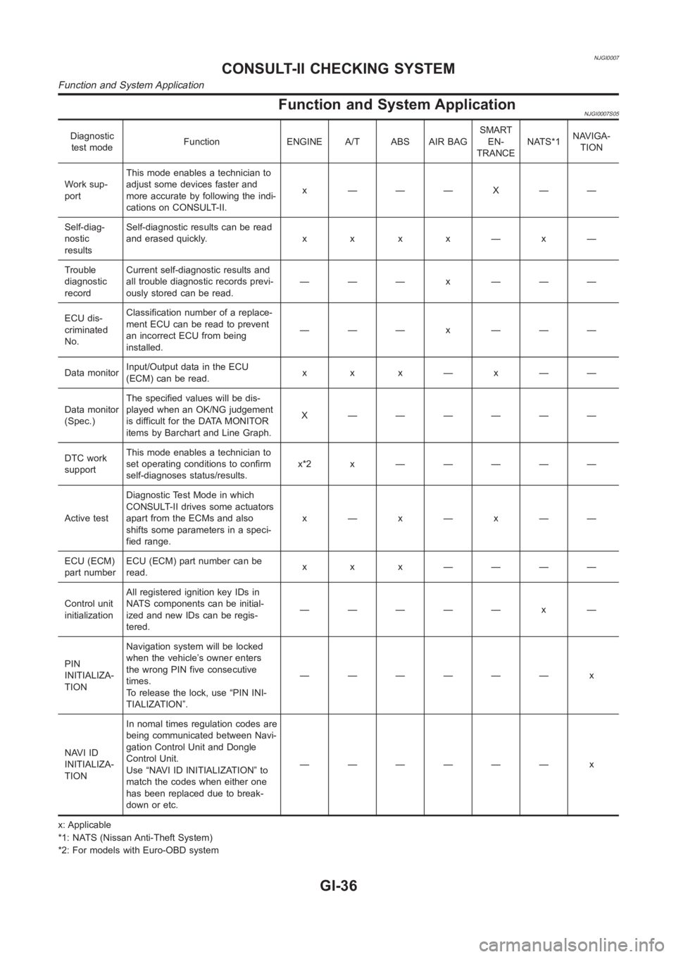
NJGI0007
Function and System ApplicationNJGI0007S05
Diagnostic
test modeFunction ENGINE A/T ABS AIR BAGSMART
EN-
TRANCENATS*1NAVIGA-
TION
Work sup-
portThis mode enables a technician to
adjust some devices faster and
more accurate by following the indi-
cations on CONSULT-II.x ———X——
Self-diag-
nostic
resultsSelf-diagnostic results can be read
anderasedquickly. x x x x—x—
Trouble
diagnostic
recordCurrent self-diagnostic results and
all trouble diagnostic records previ-
ously stored can be read.——— x ———
ECU dis-
criminated
No.Classification number of a replace-
ment ECU can be read to prevent
an incorrect ECU from being
installed.——— x ———
Data monitorInput/Output data in the ECU
(ECM) can be read.x x x—x——
Data monitor
(Spec.)The specified values will be dis-
played when an OK/NG judgement
is difficult for the DATA MONITOR
items by Barchart and Line Graph.X ——————
DTC work
supportThis mode enables a technician to
set operating conditions to confirm
self-diagnoses status/results.x*2x —————
Active testDiagnostic Test Mode in which
CONSULT-II drives some actuators
apart from the ECMs and also
shifts some parameters in a speci-
fied range.x—x—x——
ECU (ECM)
part numberECU (ECM) part number can be
read.x x x ————
Control unit
initializationAll registered ignition key IDs in
NATS components can be initial-
ized and new IDs can be regis-
tered.————— x —
PIN
INITIALIZA-
TIONNavigation system will be locked
when the vehicle’s owner enters
the wrong PIN five consecutive
times.
To release the lock, use “PIN INI-
TIALIZATION”.—————— x
NAVI ID
INITIALIZA-
TIONIn nomal times regulation codes are
being communicated between Navi-
gation Control Unit and Dongle
Control Unit.
Use “NAVI ID INITIALIZATION” to
match the codes when either one
has been replaced due to break-
down or etc.—————— x
x: Applicable
*1: NATS (Nissan Anti-Theft System)
*2: For models with Euro-OBD system
CONSULT-II CHECKING SYSTEM
Function and System Application
GI-36
Page 59 of 3189
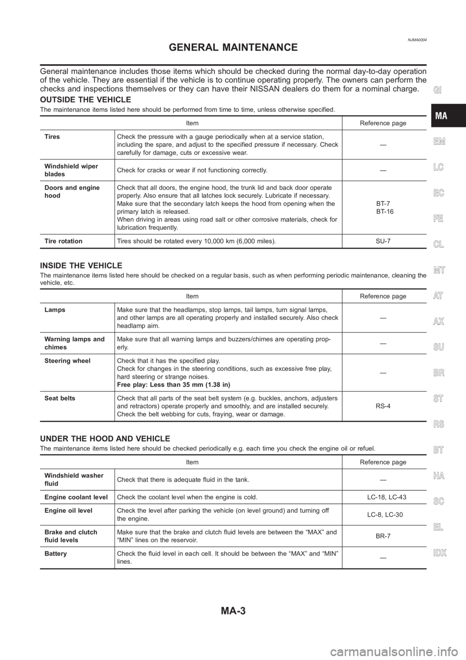
NJMA0004
General maintenance includes those items which should be checked during the normal day-to-day operation
of the vehicle. They are essential if the vehicle is to continue operating properly. The owners can perform the
checks and inspections themselves or they can have their NISSAN dealers dothem for a nominal charge.
OUTSIDE THE VEHICLE
The maintenance items listed here should be performed from time to time, unless otherwise specified.
Item Reference page
TiresCheck the pressure with a gauge periodically when at a service station,
including the spare, and adjust to the specified pressure if necessary. Check
carefully for damage, cuts or excessive wear.—
Windshield wiper
bladesCheck for cracks or wear if not functioning correctly. —
Doors and engine
hoodCheck that all doors, the engine hood, the trunk lid and back door operate
properly. Also ensure that all latches lock securely. Lubricate if necessary.
Make sure that the secondary latch keeps the hood from opening when the
primary latch is released.
When driving in areas using road salt or other corrosive materials, check for
lubrication frequently.BT-7
BT-16
Tire rotationTires should be rotated every 10,000 km (6,000 miles). SU-7
INSIDE THE VEHICLE
The maintenance items listed here should be checked on a regular basis, such as when performing periodic maintenance, cleaning the
vehicle, etc.
Item Reference page
LampsMake sure that the headlamps, stop lamps, tail lamps, turn signal lamps,
and other lamps are all operating properly and installed securely. Also check
headlamp aim.—
Warning lamps and
chimesMake sure that all warning lamps and buzzers/chimes are operating prop-
erly.—
Steering wheelCheck that it has the specified play.
Check for changes in the steering conditions, such as excessive free play,
hard steering or strange noises.
Free play: Less than 35 mm (1.38 in)—
Seat beltsCheck that all parts of the seat belt system (e.g. buckles, anchors, adjusters
and retractors) operate properly and smoothly, and are installed securely.
Check the belt webbing for cuts, fraying, wear or damage.RS-4
UNDER THE HOOD AND VEHICLE
The maintenance items listed here should be checked periodically e.g. each time you check the engine oil or refuel.
Item Reference page
Windshield washer
fluidCheck that there is adequate fluid in the tank. —
Engine coolant levelCheck the coolant level when the engine is cold. LC-18, LC-43
Engine oil levelCheck the level after parking the vehicle (on level ground) and turning off
the engine.LC-8, LC-30
Brake and clutch
fluid levelsMake sure that the brake and clutch fluid levels are between the “MAX” and
“MIN” lines on the reservoir.BR-7
BatteryCheck the fluid level in each cell. It should be between the “MAX” and “MIN”
lines.—
GI
EM
LC
EC
FE
CL
MT
AT
AX
SU
BR
ST
RS
BT
HA
SC
EL
IDX
GENERAL MAINTENANCE
MA-3
Page 88 of 3189
![NISSAN ALMERA N16 2003 Electronic Repair Manual EM-10
[QG]
NOISE, VIBRATION, AND HARSHNESS (NVH) TROUBLESHOOTING
Use the Chart Below to Help You Find the Cause of the Symptom.
EBS00LPX
1. Locate the area where noise occurs.
2. Confirm the type of n NISSAN ALMERA N16 2003 Electronic Repair Manual EM-10
[QG]
NOISE, VIBRATION, AND HARSHNESS (NVH) TROUBLESHOOTING
Use the Chart Below to Help You Find the Cause of the Symptom.
EBS00LPX
1. Locate the area where noise occurs.
2. Confirm the type of n](/img/5/57350/w960_57350-87.png)
EM-10
[QG]
NOISE, VIBRATION, AND HARSHNESS (NVH) TROUBLESHOOTING
Use the Chart Below to Help You Find the Cause of the Symptom.
EBS00LPX
1. Locate the area where noise occurs.
2. Confirm the type of noise.
3. Specify the operating condition of engine.
4. Check specified noise source.
If necessary, repair or replace these parts.
A: Closely related B: Related C: Sometimes related —: Not relatedLocation
of noiseTy p e o f
noiseOperating condition of engine
Source of
noiseCheck itemRefer-
ence page Before
warm-
upAfter
warm-
upWhen
start-
ingWhen
idlingWhen
racingWhile
driving
Top of
engine
Rocker
cover
Cylinder
headTick in g o r
clickingCA—AB—Tappet
noise
●Valve clearanceEM-42
Rattle C A — A B CCamshaft
bearing
noise
●Camshaft journal
clearance
●Camshaft runoutEM-39EM-39
Crank-
shaft pul-
ley
Cylinder
block
(Side of
engine)
Oil panSlap or
knock—A—B B—Piston pin
noise
●Piston and piston pin
clearance
●Connecting rod
bushing clearanceEM-84EM-87
Slap or
rapA——B B APiston
slap noise
●Piston-to-bore clear-
ance
●Piston ring side
clearance
●Piston ring end gap
●Connecting rod bend
and torsionEM-88
EM-85
EM-86
EM-86
Knock A B C B B BConnect-
ing rod
bearing
noise
●Connecting rod
bushing clearance
(Small end)
●Connecting rod bear-
ing clearance (Big
end)EM-87EM-87
Knock A B — A B CMain
bearing
noise
●Main bearing oil
clearance
●Crankshaft runoutEM-91EM-90
Front of
engine
Timing
chain
coverTapping or
tickingAA—BBBTiming
chain and
chain ten-
sioner
noise●Timing chain cracks
and wear
●Timing chain ten-
sioner operationEM-51EM-47
Front of
engineSqueak-
ing or fizz-
ingAB—B—CDrive belts
(Sticking
or slip-
ping)
●Drive belts deflection
EM-11
CreakingABABABDrive belts
(Slipping)●Idler pulley bearing
operation
Squall
CreakAB—BABWater
pump
noise
●Water pump opera-
tionLC-14