air conditioning NISSAN ALMERA N16 2003 Electronic Owner's Manual
[x] Cancel search | Manufacturer: NISSAN, Model Year: 2003, Model line: ALMERA N16, Model: NISSAN ALMERA N16 2003Pages: 3189, PDF Size: 54.76 MB
Page 2813 of 3189
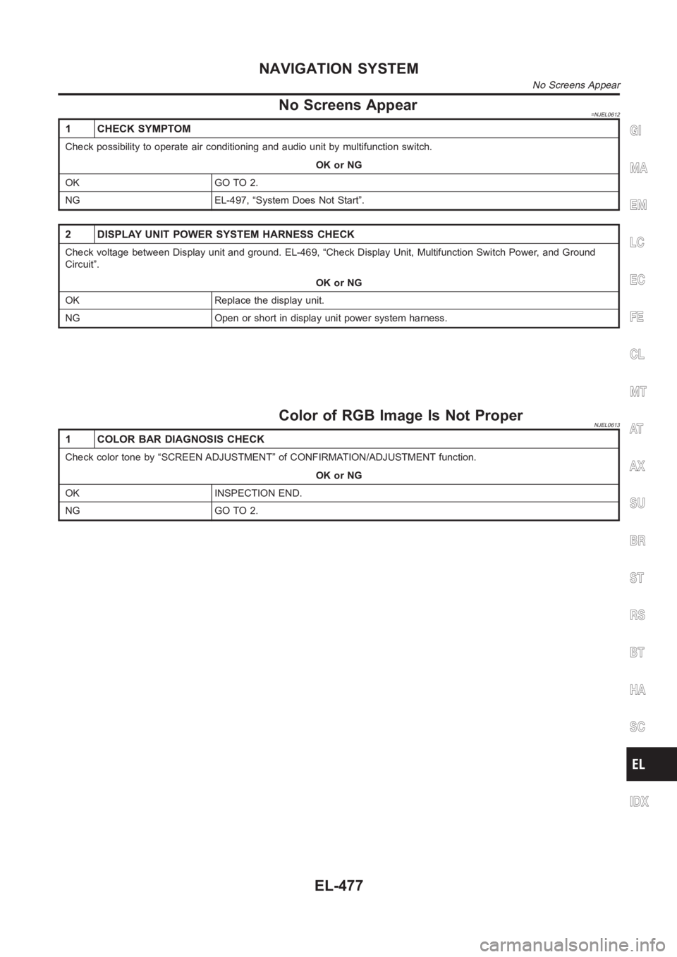
No Screens Appear=NJEL0612
1 CHECK SYMPTOM
Check possibility to operate air conditioning and audio unit by multifunction switch.
OK or NG
OK GO TO 2.
NG EL-497, “System Does Not Start”.
2 DISPLAY UNIT POWER SYSTEM HARNESS CHECK
Check voltage between Display unit and ground. EL-469, “Check Display Unit, Multifunction Switch Power, and Ground
Circuit”.
OK or NG
OK Replace the display unit.
NG Open or short in display unit power system harness.
Color of RGB Image Is Not ProperNJEL0613
1 COLOR BAR DIAGNOSIS CHECK
Check color tone by “SCREEN ADJUSTMENT” of CONFIRMATION/ADJUSTMENT function.
OK or NG
OK INSPECTION END.
NG GO TO 2.
GI
MA
EM
LC
EC
FE
CL
MT
AT
AX
SU
BR
ST
RS
BT
HA
SC
IDX
NAVIGATION SYSTEM
No Screens Appear
EL-477
Page 2825 of 3189
Air Conditioning Controls (Only) Are Ineffective
(Rear Defogger Control Excluded)
NJEL0617
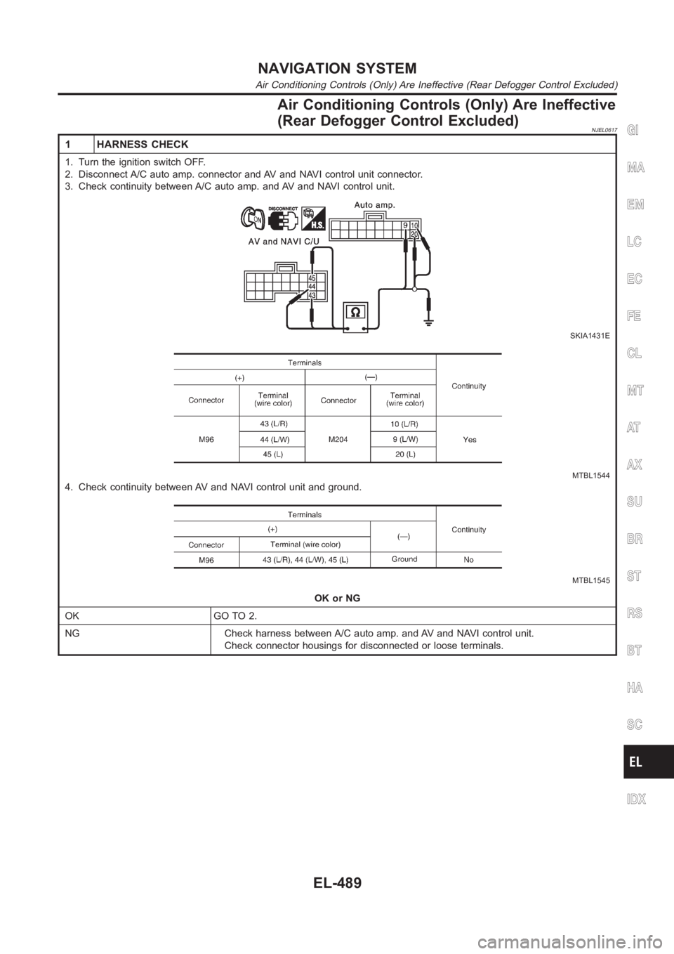
1 HARNESS CHECK
1. Turn the ignition switch OFF.
2. Disconnect A/C auto amp. connector and AV and NAVI control unit connector.
3. Check continuity between A/C auto amp. and AV and NAVI control unit.
SKIA1431E
MTBL1544
4. Check continuity between AV and NAVI control unit and ground.
MTBL1545
OK or NG
OK GO TO 2.
NG Check harness between A/C auto amp. and AV and NAVI control unit.
Check connector housings for disconnected or loose terminals.
GI
MA
EM
LC
EC
FE
CL
MT
AT
AX
SU
BR
ST
RS
BT
HA
SC
IDX
NAVIGATION SYSTEM
Air Conditioning Controls (Only) Are Ineffective (Rear Defogger ControlExcluded)
EL-489
Page 2826 of 3189
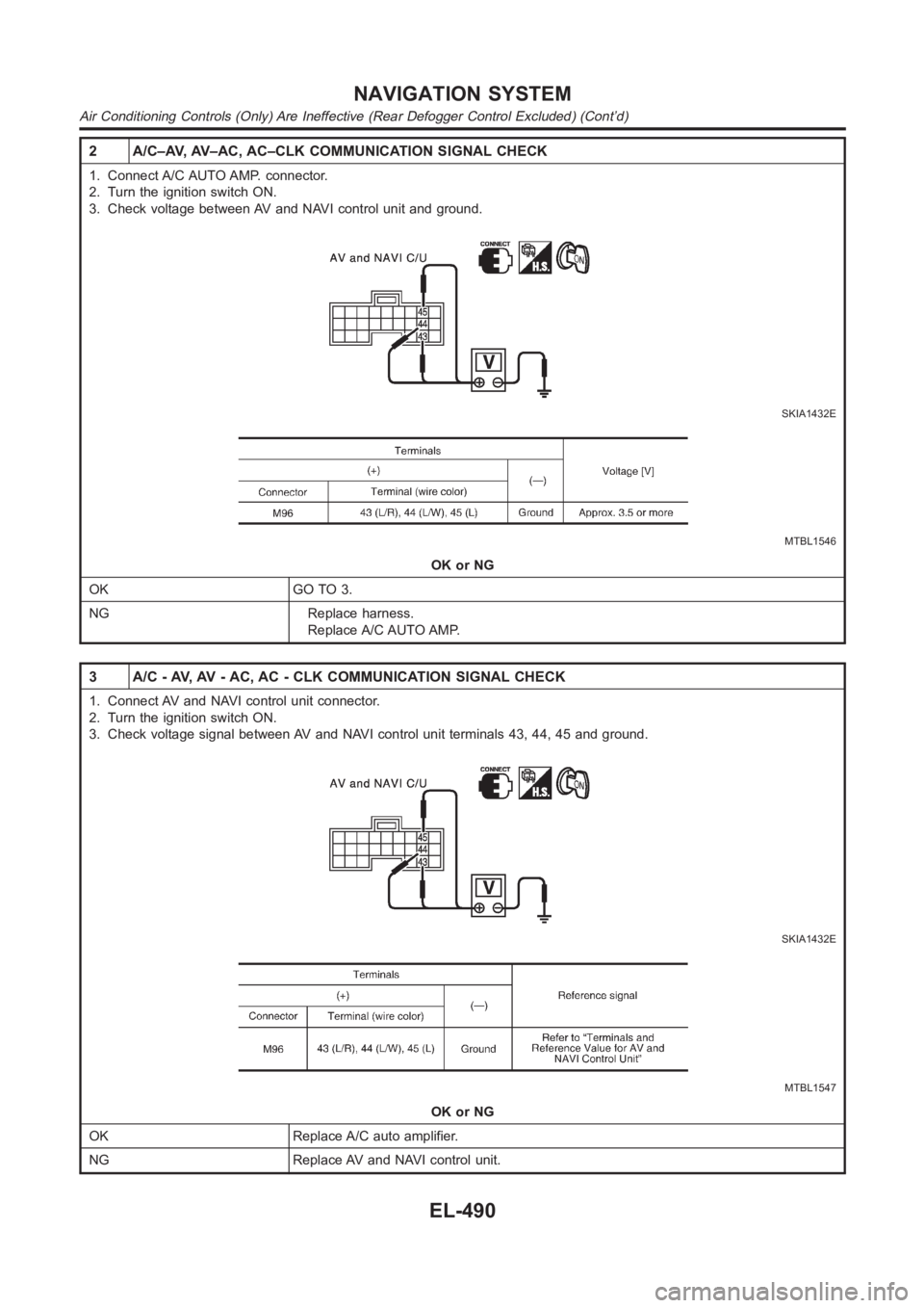
2 A/C–AV, AV–AC, AC–CLK COMMUNICATION SIGNAL CHECK
1. Connect A/C AUTO AMP. connector.
2. Turn the ignition switch ON.
3. Check voltage between AV and NAVI control unit and ground.
SKIA1432E
MTBL1546
OK or NG
OK GO TO 3.
NG Replace harness.
Replace A/C AUTO AMP.
3 A/C - AV, AV - AC, AC - CLK COMMUNICATION SIGNAL CHECK
1. Connect AV and NAVI control unit connector.
2. Turn the ignition switch ON.
3. Check voltage signal between AV and NAVI control unit terminals 43, 44, 45 and ground.
SKIA1432E
MTBL1547
OK or NG
OK Replace A/C auto amplifier.
NG Replace AV and NAVI control unit.
NAVIGATION SYSTEM
Air Conditioning Controls (Only) Are Ineffective (Rear Defogger ControlExcluded) (Cont’d)
EL-490
Page 2938 of 3189
Supplemental Restraint System (SRS) “AIR
BAG” and “SEAT BELT PRE-TENSIONER”
NJHA0190The Supplemental Restraint System such as “AIR BAG” and “SEAT BELT PRE-TENSIONER” used along with
a seat belt, helps to reduce the risk or severity of injury to the driver and front passenger for certain types of
collision. The SRS system composition which is available to NISSAN MODEL N16 is as follows (The compo-
sition varies according to the destination and optional equipment.):
For a frontal collision
The Supplemental Restraint System consists of driver air bag module (located in the center of the steer-
ing wheel), front passenger air bag module (located on the instrument panel on passenger side), front seat
belt pre-tensioners, a diagnosis sensor unit, warning lamp, wiring harness and spiral cable.
For a side collision
The Supplemental Restraint System consists of front side air bag module (located in the outer side of front
seat), side air bag (satellite) sensor, diagnosis sensor unit (one of components of air bags for a frontal
collision), wiring harness, warning lamp (one of components of air bags for a frontal collision).
Information necessary to service the system safely is included in theRS sectionof this Service Manual.
WARNING:
To avoid rendering the SRS inoperative, which could increase the risk of personal injury or death
in the event of a collision which would result in air bag inflation, all maintenance should be per-
formed by an authorized NISSAN dealer.
Improper maintenance, including incorrect removal and installation of the SRS, can lead to per-
sonal injury caused by unintentional activation of the system. For removalofSpiralCableandAir
Bag Module, see the RS section.
Do not use electrical test equipment on any circuit related to the SRS unless instructed to in this
Service Manual. Spiral cable and wiring harnesses covered with yellow and/or orange insulation
tape either just before the harness connectors or for the complete harnessare related to the SRS.
Precautions for Working with HFC-134a
(R-134a)
NJHA0113WARNING:
CFC-12 (R-12) refrigerant and HFC-134a (R-134a) refrigerant are not compatible. These refrigerants
must never be mixed, even in the smallest amounts. If the refrigerants are mixed, compressor
malfunction is likely to occur.
Use only specified lubricant for the HFC-134a (R-134a) A/C system and HFC-134a (R-134a) compo-
nents. If lubricant other than that specified is used, compressor malfunction is likely to occur.
The specified HFC-134a (R-134a) lubricant rapidly absorbs moisture fromthe atmosphere. The fol-
lowing handling precautions must be observed:
a) When removing refrigerant components from a vehicle, immediately cap (seal) the component to
minimize the entry of moisture from the atmosphere.
b) When installing refrigerant components to a vehicle, do not remove the caps (unseal) until just
before connecting the components. Connect all refrigerant loop components as quickly as pos-
sible to minimize the entry of moisture into system.
c) Only use the specified lubricant from a sealed container. Immediately reseal containers of lubri-
cant. Without proper sealing, lubricant will become moisture saturated and should not be used.
d) Avoid breathing A/C refrigerant and lubricant vapor or mist. Exposure may irritate eyes, nose and
throat. Remove HFC-134a (R-134a) from the A/C system, using certified service equipment meet-
ing requirements of HFC-134a (R-134a) recycling equipment, or HFC-134a (R-134a) recovery equip-
ment. If accidental system discharge occurs, ventilate work area before resuming service. Addi-
tional health and safety information may be obtained from refrigerant andlubricant manufactur-
ers.
e) Do not allow lubricant (Nissan A/C System Oil Type S) to come in contact with styrofoam parts.
Damage may result.
General Refrigerant PrecautionsNJHA0114WARNING:
Do not release refrigerant into the air. Use approved recovery/recyclingequipment to capture the
refrigerant every time an air conditioning system is discharged.
PRECAUTIONSMANUAL
Supplemental Restraint System (SRS) “AIR BAG” and “SEAT BELT PRE-TENSIONER”
HA-2
Page 2939 of 3189
Always wear eye and hand protection (goggles and gloves) when working withany refrigerant or
air conditioning system.
Do not store or heat refrigerant containers above 52°C (125°F).
Do not heat a refrigerant container with an open flame; if container warming is required, place the
bottom of the container in a warm pail of water.
Do not intentionally drop, puncture, or incinerate refrigerant containers.
Keep refrigerant away from open flames: poisonous gas will be produced if refrigerant burns.
Refrigerant will displace oxygen, therefore be certain to work in well ventilated areas to prevent
suffocation.
Do not pressure test or leak test HFC-134a (R-134a) service equipment and/or vehicle air condi-
tioning systems with compressed air during repair. Some mixtures of air and HFC-134a (R-134a)
have been shown to be combustible at elevated pressures. These mixtures, if ignited, may cause
injury or property damage. Additional health and safety information may be obtained from refrig-
erant manufacturers.
Precautions for Refrigerant ConnectionNJHA0115A new type refrigerant connection has been introduced to all refrigerant lines except the following portion.
Expansion valve to evaporator
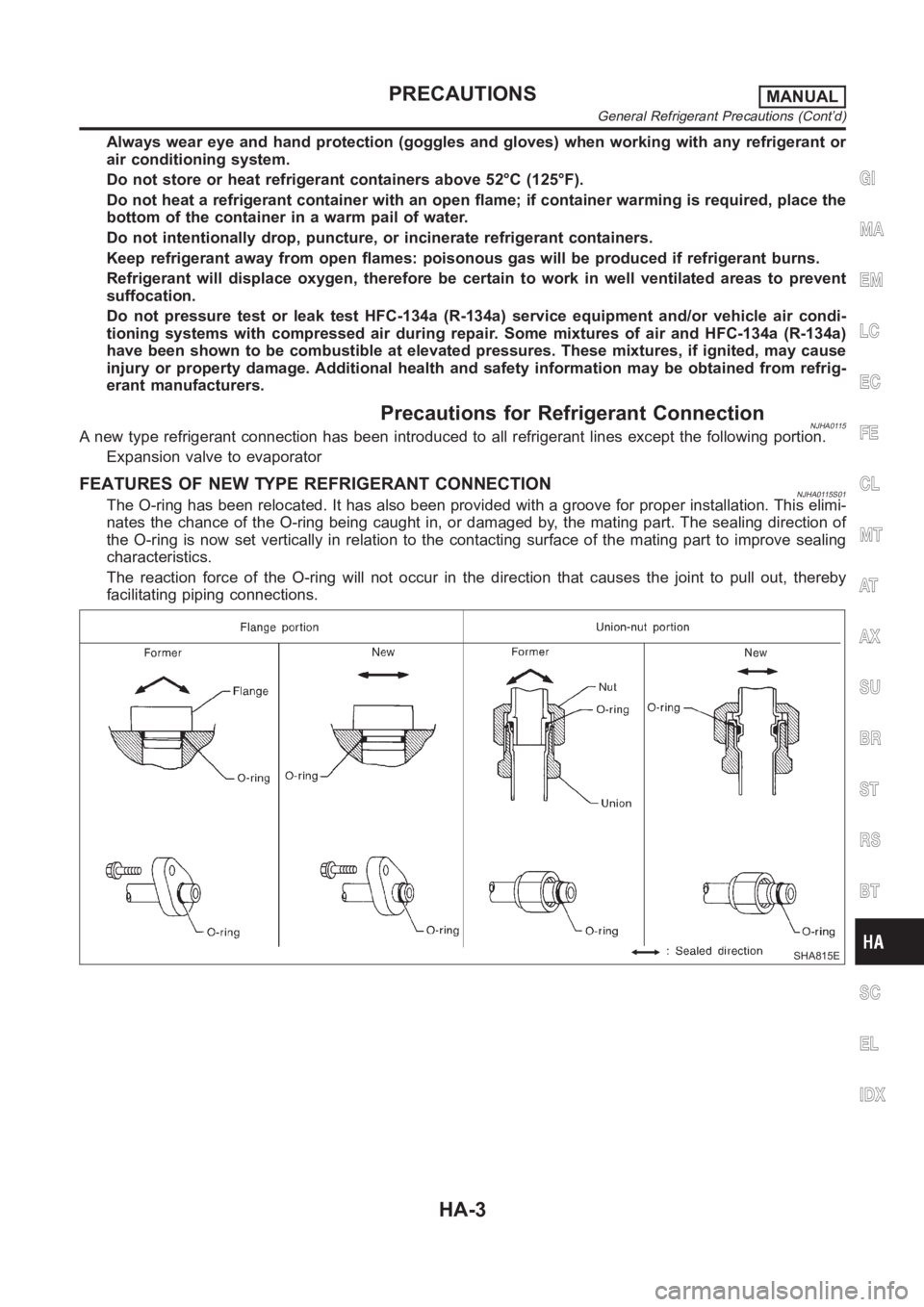
FEATURES OF NEW TYPE REFRIGERANT CONNECTIONNJHA0115S01The O-ring has been relocated. It has also been provided with a groove for proper installation. This elimi-
nates the chance of the O-ring being caught in, or damaged by, the mating part. The sealing direction of
the O-ring is now set vertically in relation to the contacting surface of the mating part to improve sealing
characteristics.
The reaction force of the O-ring will not occur in the direction that causesthe joint to pull out, thereby
facilitating piping connections.
SHA815E
GI
MA
EM
LC
EC
FE
CL
MT
AT
AX
SU
BR
ST
RS
BT
SC
EL
IDX
PRECAUTIONSMANUAL
General Refrigerant Precautions (Cont’d)
HA-3
Page 2949 of 3189
CSV613 Variable Displacement Compressor
GENERAL INFORMATIONNJHA02061. The CSV613 compressor differs from previous units. The vent temperatures of the CSV613 compressor
do not drop too far below 5°C (41°F) when:
evaporator intake air temperature is less than 20°C (68°F)
engine is running at speeds less than 1,500 rpm.
This is because the CSV613 compressor provides a means of “capacity” control.
2. The CSV613 compressor provides refrigerant control under varying conditions. During cold winters, it may
not produce high refrigerant pressure discharge (compared to previous units) when used with air condi-
tioning systems.
3. A “clanking” sound may occasionally be heard during refrigerant charge. The sound indicates that the tilt
angle of the swash plate has changed and is not a problem.
4. For air conditioning systems with the CSV613 compressor, the clutch remains engaged unless: the sys-
tem main switch, fan switch or ignition switch is turned OFF. When ambient (outside) temperatures are
low or when the amount of refrigerant is insufficient, the clutch is disengaged to protect the compressor.
5. A constant range of suction pressure is maintained when engine speed is greater than a certain value. It
normally ranges from 147 to 177 kPa (1.47 to 1.77 bar, 1.5 to 1.8 kg/cm
2, 21 to 26 psi) under varying con-
ditions.
In previous compressors, however, suction pressure was reduced with increases in engine speed.
GI
MA
EM
LC
EC
FE
CL
MT
AT
AX
SU
BR
ST
RS
BT
SC
EL
IDX
DESCRIPTIONMANUAL
CSV613 Variable Displacement Compressor
HA-13
Page 3005 of 3189
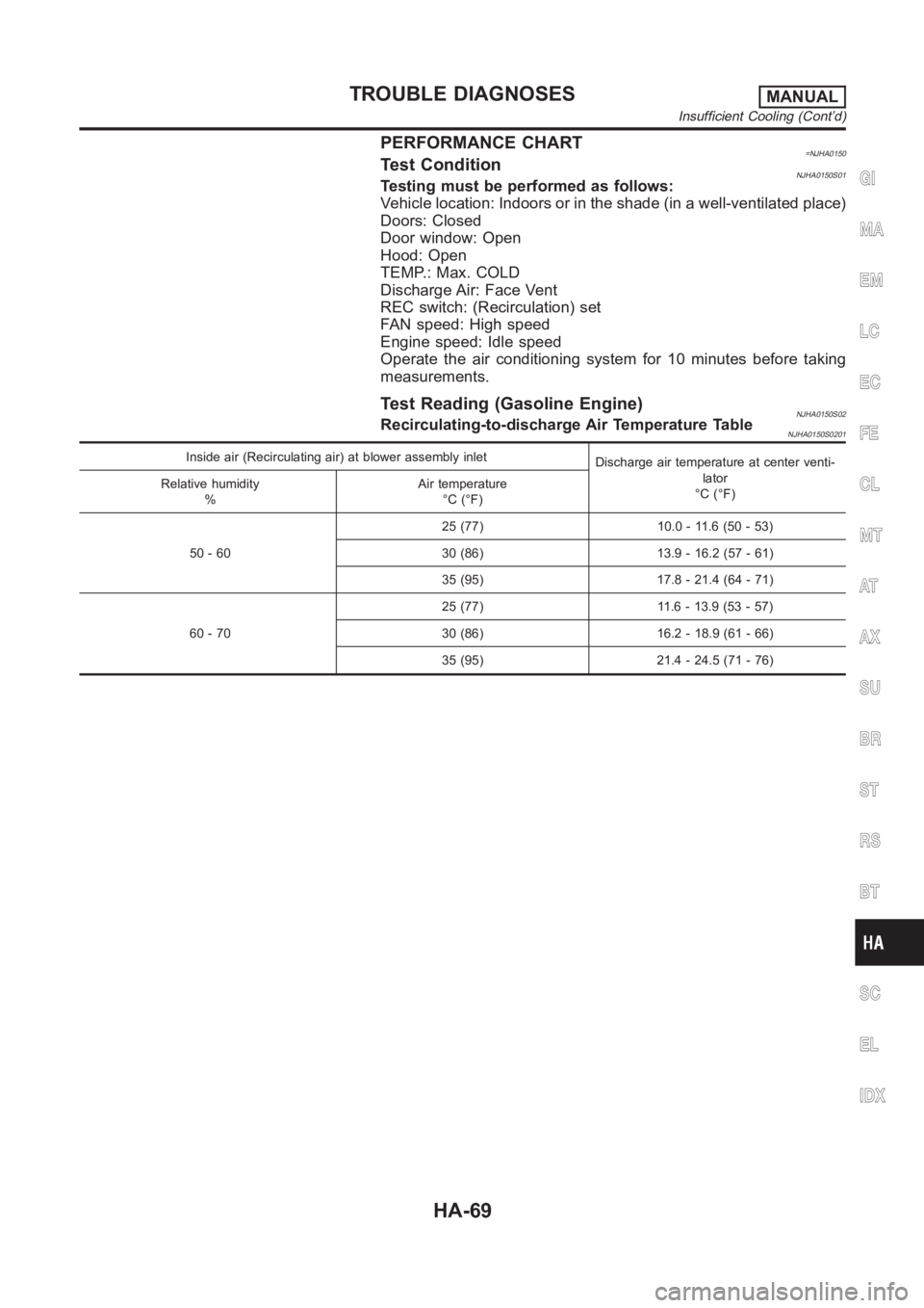
PERFORMANCE CHART=NJHA0150Test ConditionNJHA0150S01Testing must be performed as follows:
Vehicle location: Indoors or in the shade (in a well-ventilated place)
Doors: Closed
Door window: Open
Hood: Open
TEMP.: Max. COLD
Discharge Air: Face Vent
REC switch: (Recirculation) set
FAN speed: High speed
Engine speed: Idle speed
Operate the air conditioning system for 10 minutes before taking
measurements.
Test Reading (Gasoline Engine)NJHA0150S02Recirculating-to-discharge Air Temperature TableNJHA0150S0201
Inside air (Recirculating air) at blower assembly inlet
Discharge air temperature at center venti-
lator
°C (°F) Relative humidity
%Air temperature
°C (°F)
50 - 6025 (77) 10.0 - 11.6 (50 - 53)
30 (86) 13.9 - 16.2 (57 - 61)
35 (95) 17.8 - 21.4 (64 - 71)
60 - 7025 (77) 11.6 - 13.9 (53 - 57)
30 (86) 16.2 - 18.9 (61 - 66)
35 (95) 21.4 - 24.5 (71 - 76)
GI
MA
EM
LC
EC
FE
CL
MT
AT
AX
SU
BR
ST
RS
BT
SC
EL
IDX
TROUBLE DIAGNOSESMANUAL
Insufficient Cooling (Cont’d)
HA-69
Page 3009 of 3189
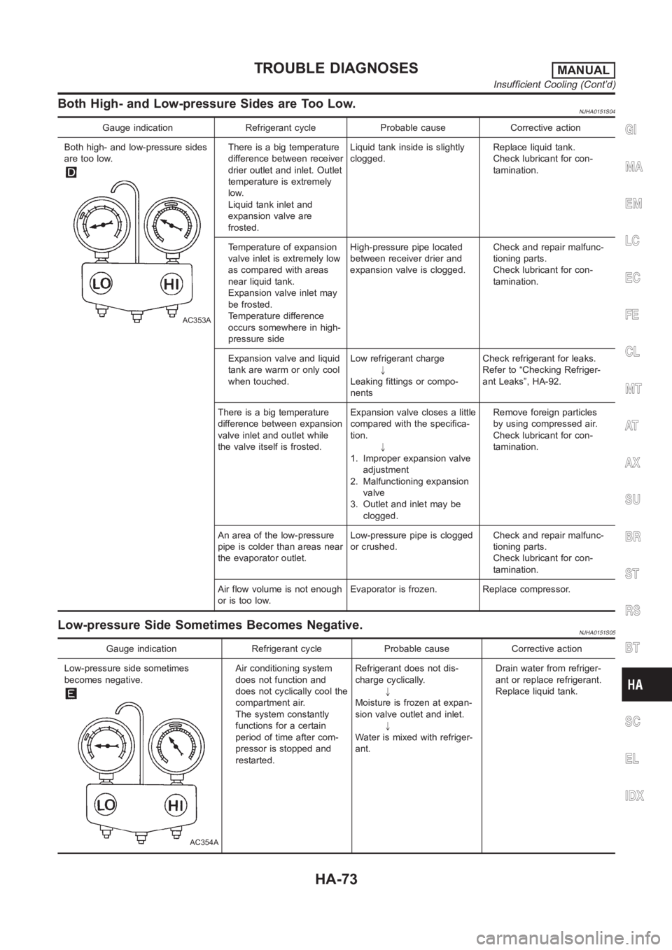
Both High- and Low-pressure Sides are Too Low.NJHA0151S04
Gauge indication Refrigerant cycle Probable cause Corrective action
Both high- and low-pressure sides
are too low.
AC353A
There is a big temperature
difference between receiver
drier outlet and inlet. Outlet
temperature is extremely
low.
Liquid tank inlet and
expansion valve are
frosted.Liquid tank inside is slightly
clogged.Replace liquid tank.
Check lubricant for con-
tamination.
Temperature of expansion
valve inlet is extremely low
as compared with areas
near liquid tank.
Expansion valve inlet may
be frosted.
Temperature difference
occurs somewhere in high-
pressure sideHigh-pressure pipe located
between receiver drier and
expansion valve is clogged.Check and repair malfunc-
tioning parts.
Check lubricant for con-
tamination.
Expansion valve and liquid
tank are warm or only cool
when touched.Low refrigerant charge
"
Leaking fittings or compo-
nentsCheck refrigerant for leaks.
Refer to “Checking Refriger-
ant Leaks”, HA-92.
There is a big temperature
difference between expansion
valve inlet and outlet while
the valve itself is frosted.Expansion valve closes a little
compared with the specifica-
tion.
"
1. Improper expansion valve
adjustment
2. Malfunctioning expansion
valve
3. Outlet and inlet may be
clogged.Remove foreign particles
by using compressed air.
Check lubricant for con-
tamination.
An area of the low-pressure
pipe is colder than areas near
the evaporator outlet.Low-pressure pipe is clogged
or crushed.Check and repair malfunc-
tioning parts.
Check lubricant for con-
tamination.
Air flow volume is not enough
or is too low.Evaporator is frozen. Replace compressor.
Low-pressure Side Sometimes Becomes Negative.NJHA0151S05
Gauge indication Refrigerant cycle Probable cause Corrective action
Low-pressure side sometimes
becomes negative.
AC354A
Air conditioning system
does not function and
does not cyclically cool the
compartment air.
The system constantly
functions for a certain
period of time after com-
pressor is stopped and
restarted.Refrigerant does not dis-
charge cyclically.
"
Moisture is frozen at expan-
sion valve outlet and inlet.
"
Water is mixed with refriger-
ant.Drain water from refriger-
ant or replace refrigerant.
Replace liquid tank.
GI
MA
EM
LC
EC
FE
CL
MT
AT
AX
SU
BR
ST
RS
BT
SC
EL
IDX
TROUBLE DIAGNOSESMANUAL
Insufficient Cooling (Cont’d)
HA-73