fuse block NISSAN ALMERA N16 2003 Electronic Owner's Manual
[x] Cancel search | Manufacturer: NISSAN, Model Year: 2003, Model line: ALMERA N16, Model: NISSAN ALMERA N16 2003Pages: 3189, PDF Size: 54.76 MB
Page 1128 of 3189
DIAGNOSTIC PROCEDURENJEC0641
1 INSPECTION START
Start engine.
Is engine running?
YesorNo
Yes GO TO 13.
No GO TO 2.
2 CHECK ECM POWER SUPPLY CIRCUIT-I
1. Turn ignition switch “ON”.
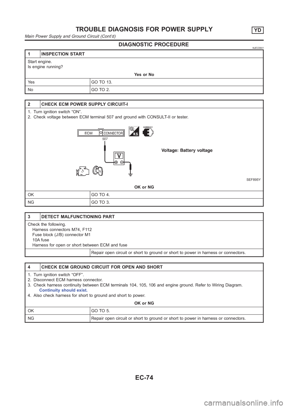
2. Check voltage between ECM terminal 507 and ground with CONSULT-II or tester.
SEF895Y
OK or NG
OK GO TO 4.
NG GO TO 3.
3 DETECT MALFUNCTIONING PART
Check the following.
Harness connectors M74, F112
Fuse block (J/B) connector M1
10A fuse
Harness for open or short between ECM and fuse
Repair open circuit or short to ground or short to power in harness or connectors.
4 CHECK ECM GROUND CIRCUIT FOR OPEN AND SHORT
1. Turn ignition switch “OFF”.
2. Disconnect ECM harness connector.
3. Check harness continuity between ECM terminals 104, 105, 106 and engineground. Refer to Wiring Diagram.
Continuity should exist.
4. Also check harness for short to ground and short to power.
OK or NG
OK GO TO 5.
NG Repair open circuit or short to ground or short to power in harness or connectors.
TROUBLE DIAGNOSIS FOR POWER SUPPLYYD
Main Power Supply and Ground Circuit (Cont’d)
EC-74
Page 1166 of 3189
Diagnostic ProcedureNJEC0743
1 CHECK STOP LAMP SWITCH CIRCUIT
1. Turn ignition switch “OFF”.
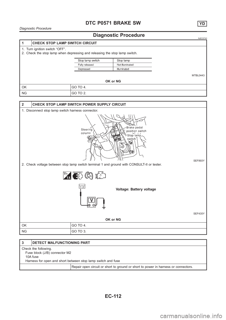
2. Check the stop lamp when depressing and releasing the stop lamp switch.
MTBL0443
OK or NG
OK GO TO 4.
NG GO TO 2.
2 CHECK STOP LAMP SWITCH POWER SUPPLY CIRCUIT
1. Disconnect stop lamp switch harness connector.
SEF893Y
2. Check voltage between stop lamp switch terminal 1 and ground with CONSULT-II or tester.
SEF435Y
OK or NG
OK GO TO 4.
NG GO TO 3.
3 DETECT MALFUNCTIONING PART
Check the following.
Fuse block (J/B) connector M2
10A fuse
Harness for open and short between stop lamp switch and fuse
Repair open circuit or short to ground or short to power in harness or connectors.
DTC P0571 BRAKE SWYD
Diagnostic Procedure
EC-112
Page 1193 of 3189
2 DETECT MALFUNCTIONING PART
Check the following.
Fuse block (J/B) connector E104
10A fuse
40A fusible link
Harness for open or short between cooling fan relay-1 and fuse
Harness for open or short between cooling fan relay-1 and battery
Repair open circuit or short to ground or short to power in harness or connectors.
3 CHECK COOLING FAN GROUND CIRCUIT FOR OPEN AND SHORT-I
1. Turn ignition switch “OFF”.
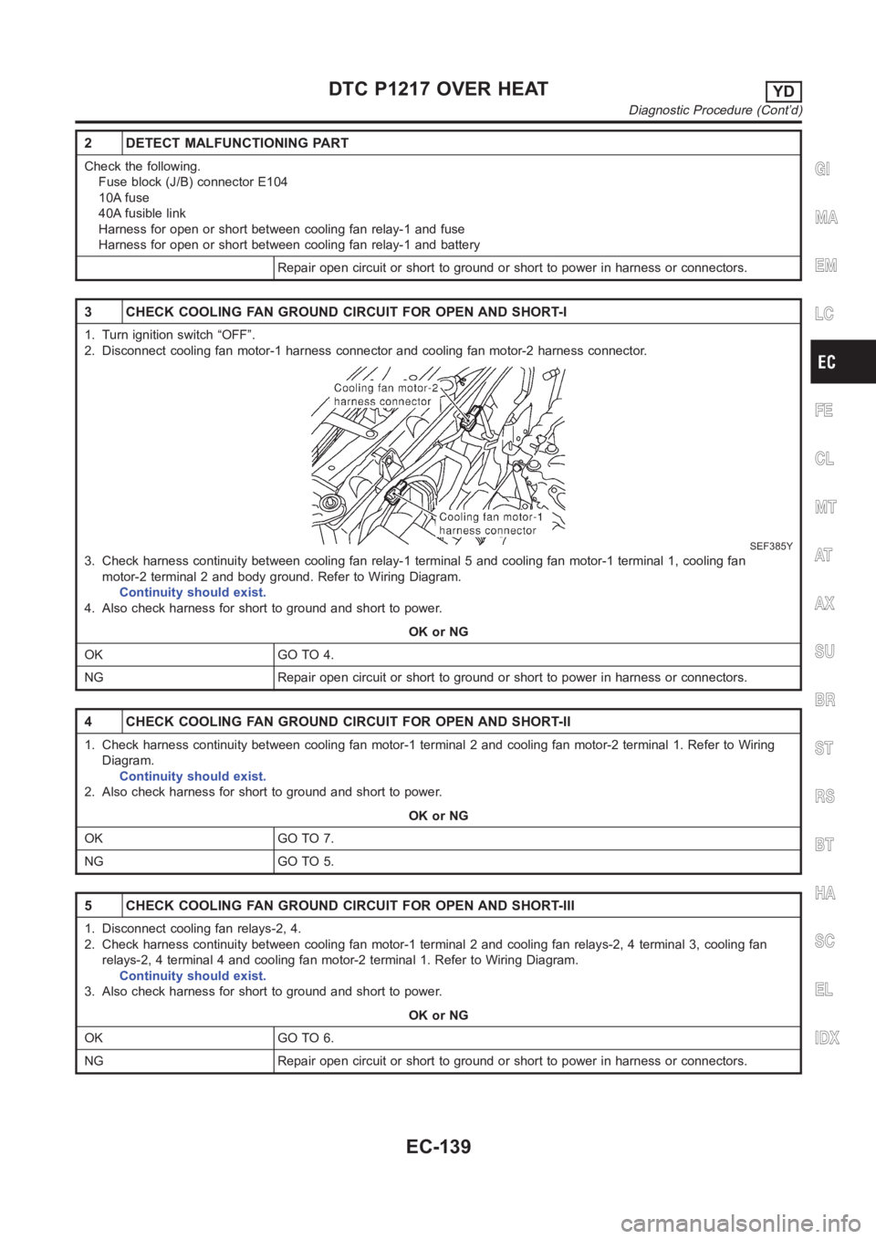
2. Disconnect cooling fan motor-1 harness connector and cooling fan motor-2 harness connector.
SEF385Y
3. Check harness continuity between cooling fan relay-1 terminal 5 and cooling fan motor-1 terminal 1, cooling fan
motor-2 terminal 2 and body ground. Refer to Wiring Diagram.
Continuity should exist.
4. Also check harness for short to ground and short to power.
OK or NG
OK GO TO 4.
NG Repair open circuit or short to ground or short to power in harness or connectors.
4 CHECK COOLING FAN GROUND CIRCUIT FOR OPEN AND SHORT-II
1. Check harness continuity between cooling fan motor-1 terminal 2 and cooling fan motor-2 terminal 1. Refer to Wiring
Diagram.
Continuity should exist.
2. Also check harness for short to ground and short to power.
OK or NG
OK GO TO 7.
NG GO TO 5.
5 CHECK COOLING FAN GROUND CIRCUIT FOR OPEN AND SHORT-III
1. Disconnect cooling fan relays-2, 4.
2. Check harness continuity between cooling fan motor-1 terminal 2 and cooling fan relays-2, 4 terminal 3, cooling fan
relays-2, 4 terminal 4 and cooling fan motor-2 terminal 1. Refer to Wiring Diagram.
Continuity should exist.
3. Also check harness for short to ground and short to power.
OK or NG
OK GO TO 6.
NG Repair open circuit or short to ground or short to power in harness or connectors.
GI
MA
EM
LC
FE
CL
MT
AT
AX
SU
BR
ST
RS
BT
HA
SC
EL
IDX
DTC P1217 OVER HEATYD
Diagnostic Procedure (Cont’d)
EC-139
Page 1247 of 3189
6 CHECK GLOW INDICATOR LAMP POWER SUPPLY CIRCUIT
1. Turn ignition switch “OFF”.
2. Disconnect combination meter harness connector M171.
3. Turn ignition switch “ON”.
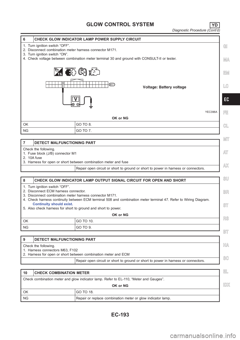
4. Check voltage between combination meter terminal 30 and ground with CONSULT-II or tester.
YEC396A
OK or NG
OK GO TO 8.
NG GO TO 7.
7 DETECT MALFUNCTIONING PART
Check the following.
1. Fuse block (J/B) connector M1
2. 10A fuse
3. Harness for open or short between combination meter and fuse
Repair open circuit or short to ground or short to power in harness or connectors.
8 CHECK GLOW INDICATOR LAMP OUTPUT SIGNAL CIRCUIT FOR OPEN AND SHORT
1. Turn ignition switch “OFF”.
2. Disconnect ECM harness connector.
3. Disconnect combination meter harness connector M171.
4. Check harness continuity between ECM terminal 508 and combination meter terminal 47. Refer to Wiring Diagram.
Continuity should exist.
5. Also check harness for short to ground and short to power.
OK or NG
OK GO TO 10.
NG GO TO 9.
9 DETECT MALFUNCTIONING PART
Check the following.
1. Harness connectors M63, F102
2. Harness for open or short between combination meter and ECM
Repair open circuit or short to ground or short to power in harness or connectors.
10 CHECK COMBINATION METER
Check combination meter and glow indicator lamp. Refer to EL-110, “Meter and Gauges”.
OK or NG
OK GO TO 18.
NG Repair or replace combination meter or glow indicator lamp.
GI
MA
EM
LC
FE
CL
MT
AT
AX
SU
BR
ST
RS
BT
HA
SC
EL
IDX
GLOW CONTROL SYSTEMYD
Diagnostic Procedure (Cont’d)
EC-193
Page 1260 of 3189
Diagnostic ProcedureNJEC0770
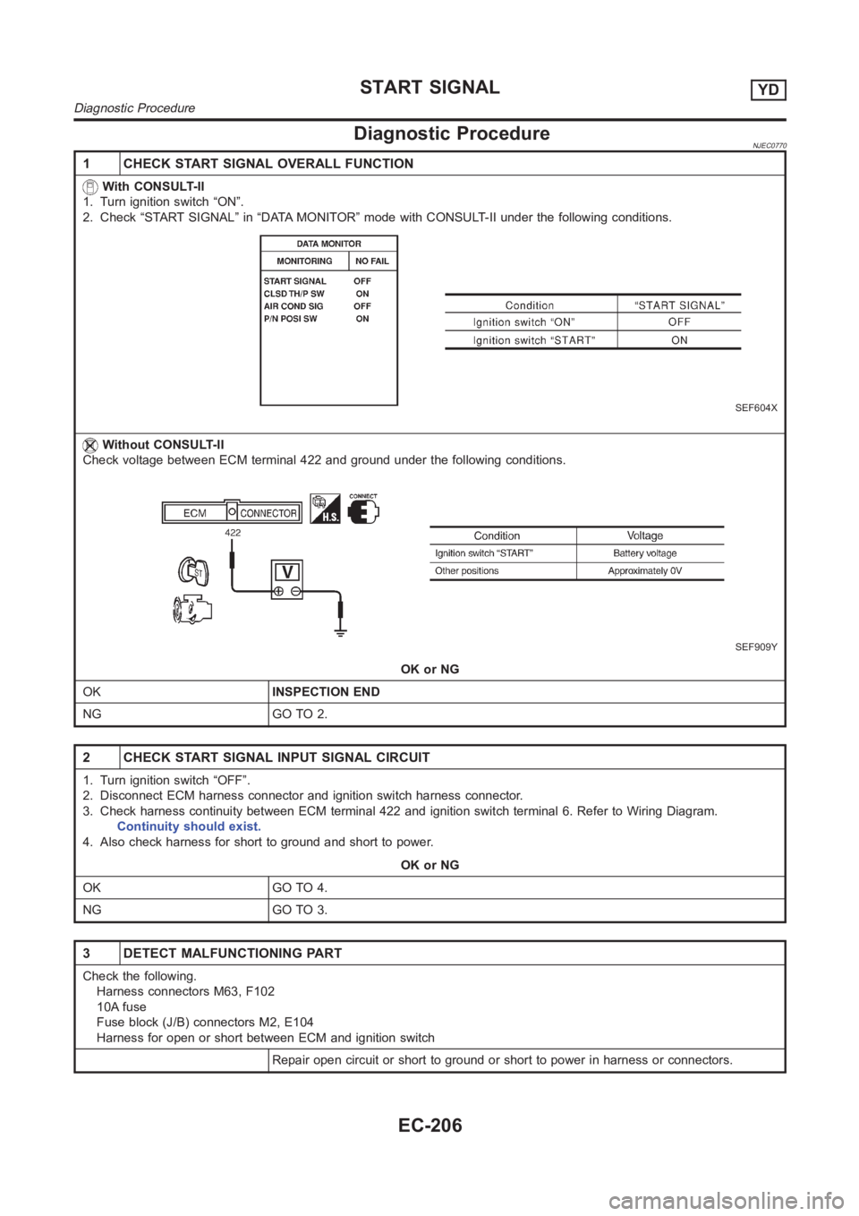
1 CHECK START SIGNAL OVERALL FUNCTION
With CONSULT-II
1. Turn ignition switch “ON”.
2. Check “START SIGNAL” in “DATA MONITOR” mode with CONSULT-II under the following conditions.
SEF604X
Without CONSULT-II
Check voltage between ECM terminal 422 and ground under the following conditions.
SEF909Y
OK or NG
OKINSPECTION END
NG GO TO 2.
2 CHECK START SIGNAL INPUT SIGNAL CIRCUIT
1. Turn ignition switch “OFF”.
2. Disconnect ECM harness connector and ignition switch harness connector.
3. Check harness continuity between ECM terminal 422 and ignition switch terminal 6. Refer to Wiring Diagram.
Continuity should exist.
4. Also check harness for short to ground and short to power.
OK or NG
OK GO TO 4.
NG GO TO 3.
3 DETECT MALFUNCTIONING PART
Check the following.
Harness connectors M63, F102
10A fuse
Fuse block (J/B) connectors M2, E104
Harness for open or short between ECM and ignition switch
Repair open circuit or short to ground or short to power in harness or connectors.
START SIGNALYD
Diagnostic Procedure
EC-206
Page 2036 of 3189
ATC-56
TROUBLE DIAGNOSIS
DIAGNOSTIC PROCEDURE FOR A/C SYSTEM
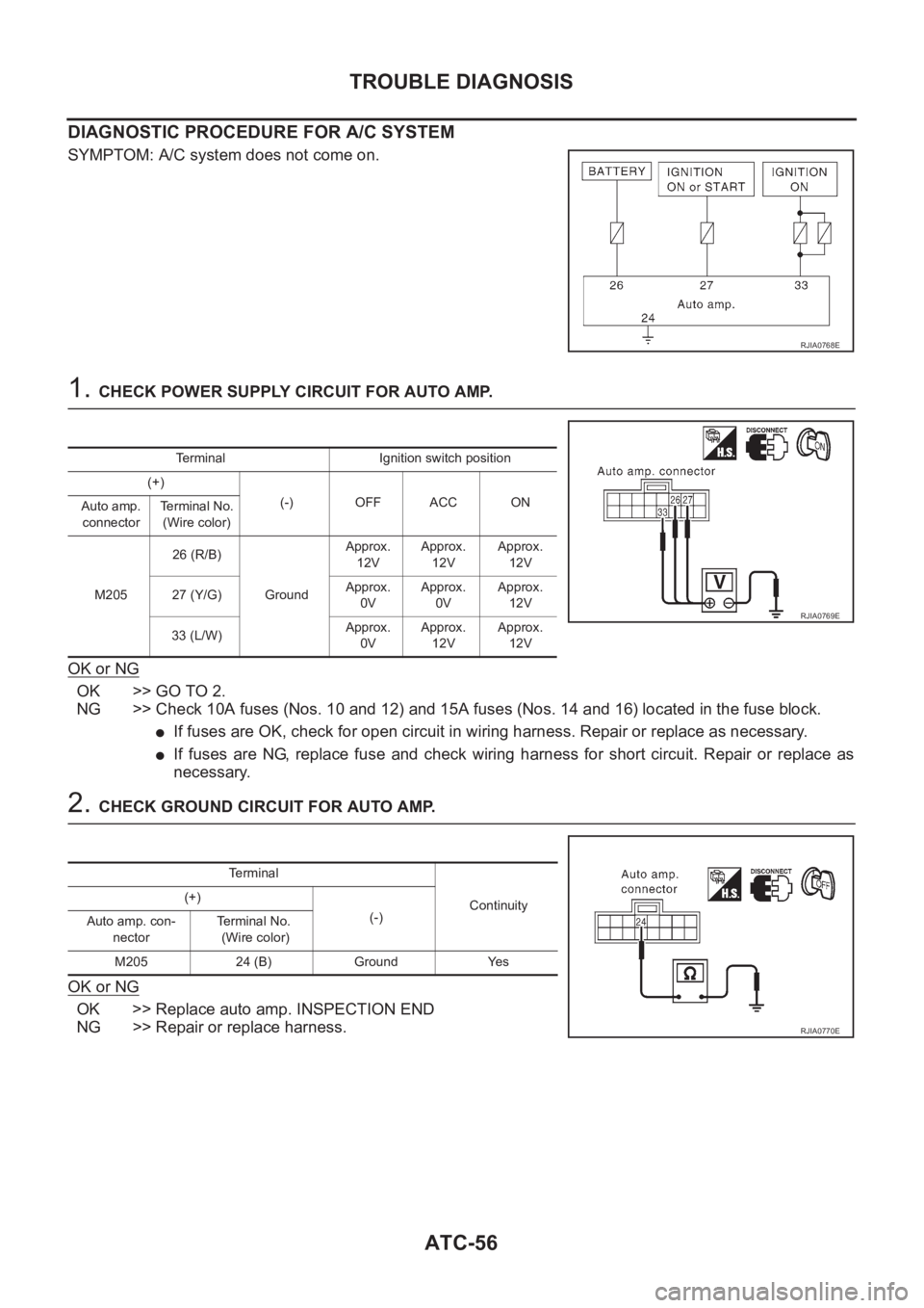
SYMPTOM: A/C system does not come on.
1. CHECK POWER SUPPLY CIRCUIT FOR AUTO AMP.
OK or NG
OK >> GO TO 2.
NG >> Check 10A fuses (Nos. 10 and 12) and 15A fuses (Nos. 14 and 16) located in the fuse block.
●If fuses are OK, check for open circuit in wiring harness. Repair or replace as necessary.
●If fuses are NG, replace fuse and check wiring harness for short circuit. Repair or replace as
necessary.
2. CHECK GROUND CIRCUIT FOR AUTO AMP.
OK or NG
OK >> Replace auto amp. INSPECTION END
NG >> Repair or replace harness.
RJIA0768E
Terminal Ignition switch position
(+)
(-) OFF ACC ON
Auto amp.
connectorTerminal No.
(Wire color)
M20526 (R/B)
GroundApprox.
12VApprox.
12VApprox.
12V
27 (Y/G)Approx.
0VApprox.
0VApprox.
12V
33 (L/W)Approx.
0VApprox.
12VApprox.
12V
RJIA0769E
Terminal
Continuity (+)
(-)
Auto amp. con-
nectorTe r m i n a l N o .
(Wire color)
M205 24 (B) Ground Yes
RJIA0770E
Page 2052 of 3189
ATC-72
TROUBLE DIAGNOSIS
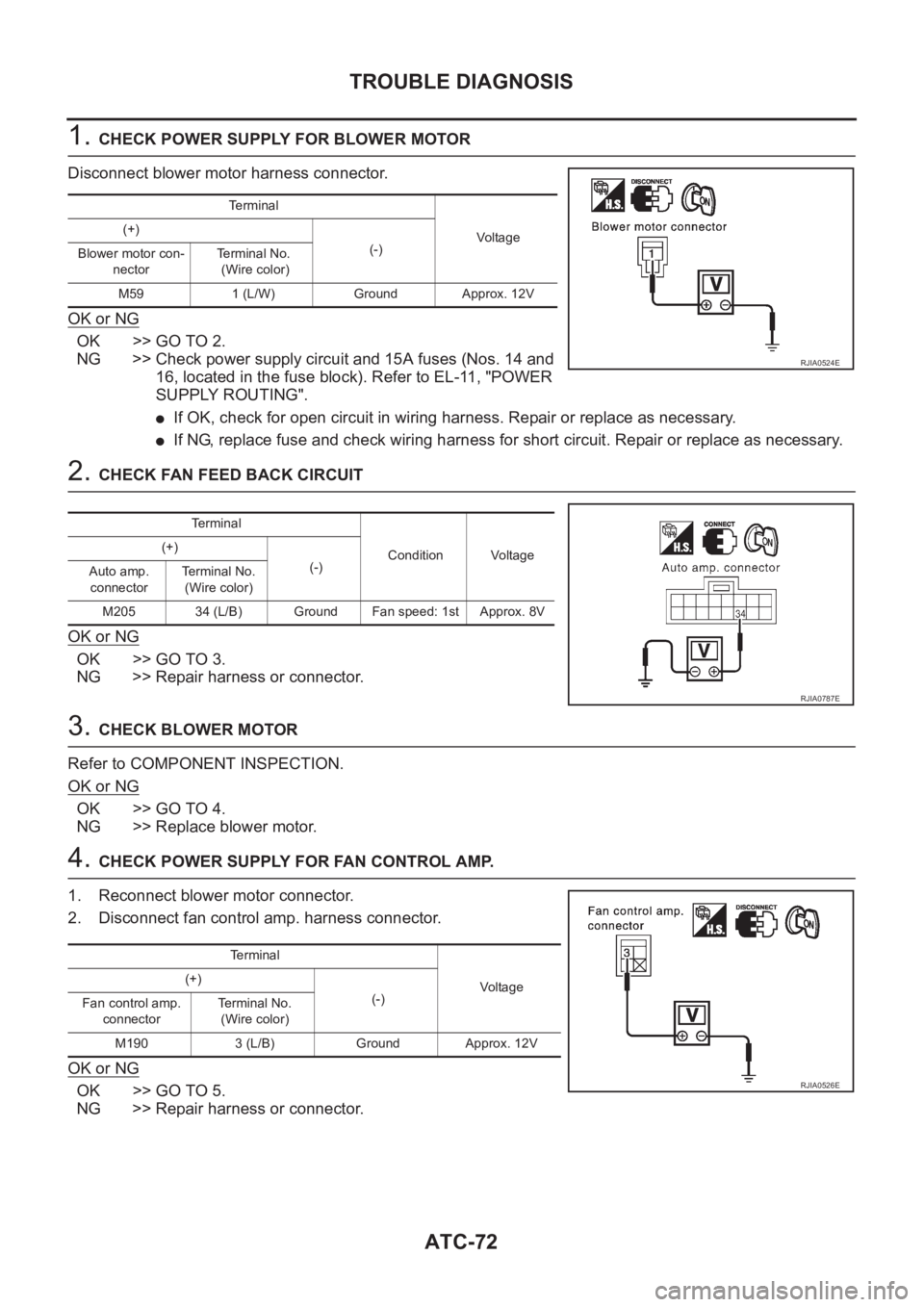
1. CHECK POWER SUPPLY FOR BLOWER MOTOR
Disconnect blower motor harness connector.
OK or NG
OK >> GO TO 2.
NG >> Check power supply circuit and 15A fuses (Nos. 14 and
16, located in the fuse block). Refer to EL-11, "POWER
SUPPLY ROUTING".
●If OK, check for open circuit in wiring harness. Repair or replace as necessary.
●If NG, replace fuse and check wiring harness for short circuit. Repair or replace as necessary.
2. CHECK FAN FEED BACK CIRCUIT
OK or NG
OK >> GO TO 3.
NG >> Repair harness or connector.
3. CHECK BLOWER MOTOR
Refer to COMPONENT INSPECTION.
OK or NG
OK >> GO TO 4.
NG >> Replace blower motor.
4. CHECK POWER SUPPLY FOR FAN CONTROL AMP.
1. Reconnect blower motor connector.
2. Disconnect fan control amp. harness connector.
OK or NG
OK >> GO TO 5.
NG >> Repair harness or connector.
Terminal
Vo l ta g e (+)
(-)
Blower motor con-
nectorTerminal No.
(Wire color)
M59 1 (L/W) Ground Approx. 12V
RJIA0524E
Te r m i n a l
Condition Voltage (+)
(-)
Auto amp.
connectorTerminal No.
(Wire color)
M205 34 (L/B) Ground Fan speed: 1st Approx. 8V
RJIA0787E
Te r m i n a l
Voltag e (+)
(-)
Fan control amp.
connectorTerminal No.
(Wire color)
M190 3 (L/B) Ground Approx. 12V
RJIA0526E
Page 2057 of 3189
TROUBLE DIAGNOSIS
ATC-77
C
D
E
F
G
H
I
K
L
MA
B
AT C
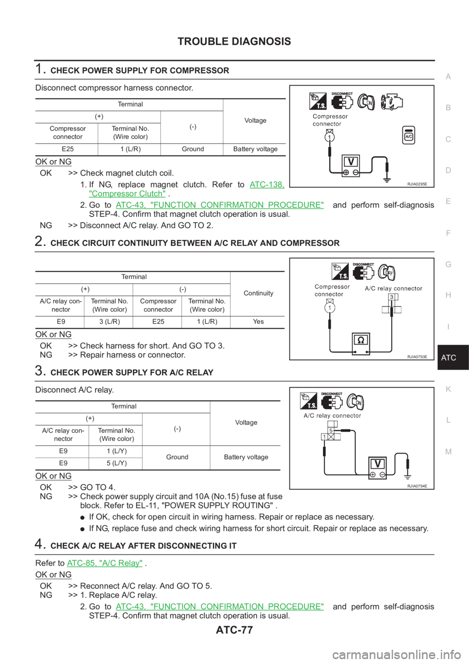
1.CHECK POWER SUPPLY FOR COMPRESSOR
Disconnect compressor harness connector.
OK or NG
OK >> Check magnet clutch coil.
1. If NG, replace magnet clutch. Refer to ATC-138,
"Compressor Clutch" .
2. Go to AT C - 4 3 , "
FUNCTION CONFIRMATION PROCEDURE" and perform self-diagnosis
STEP-4. Confirm that magnet clutch operation is usual.
NG >> Disconnect A/C relay. And GO TO 2.
2.CHECK CIRCUIT CONTINUITY BETWEEN A/C RELAY AND COMPRESSOR
OK or NG
OK >> Check harness for short. And GO TO 3.
NG >> Repair harness or connector.
3.CHECK POWER SUPPLY FOR A/C RELAY
Disconnect A/C relay.
OK or NG
OK >> GO TO 4.
NG >> Check power supply circuit and 10A (No.15) fuse at fuse
block. Refer to EL-11, "POWER SUPPLY ROUTING" .
●If OK, check for open circuit in wiring harness. Repair or replace as necessary.
●If NG, replace fuse and check wiring harness for short circuit. Repair or replace as necessary.
4.CHECK A/C RELAY AFTER DISCONNECTING IT
Refer to ATC-85, "
A/C Relay" .
OK or NG
OK >> Reconnect A/C relay. And GO TO 5.
NG >> 1. Replace A/C relay.
2. Go to AT C - 4 3 , "
FUNCTION CONFIRMATION PROCEDURE" and perform self-diagnosis
STEP-4. Confirm that magnet clutch operation is usual.
Terminal
Vo lta g e (+)
(-)
Compressor
connectorTe r m i n a l N o .
(Wire color)
E25 1 (L/R) Ground Battery voltage
RJIA0295E
Terminal
Continuity (+) (-)
A/C relay con-
nectorTerminal No.
(Wire color)Compressor
connectorTerminal No.
(Wire color)
E9 3 (L/R) E25 1 (L/R) Yes
RJIA0793E
Terminal
Vo l ta g e (+)
(-)
A/C relay con-
nectorTerminal No.
(Wire color)
E9 1 (L/Y)
Ground Battery voltage
E9 5 (L/Y)
RJIA0794E
Page 2062 of 3189
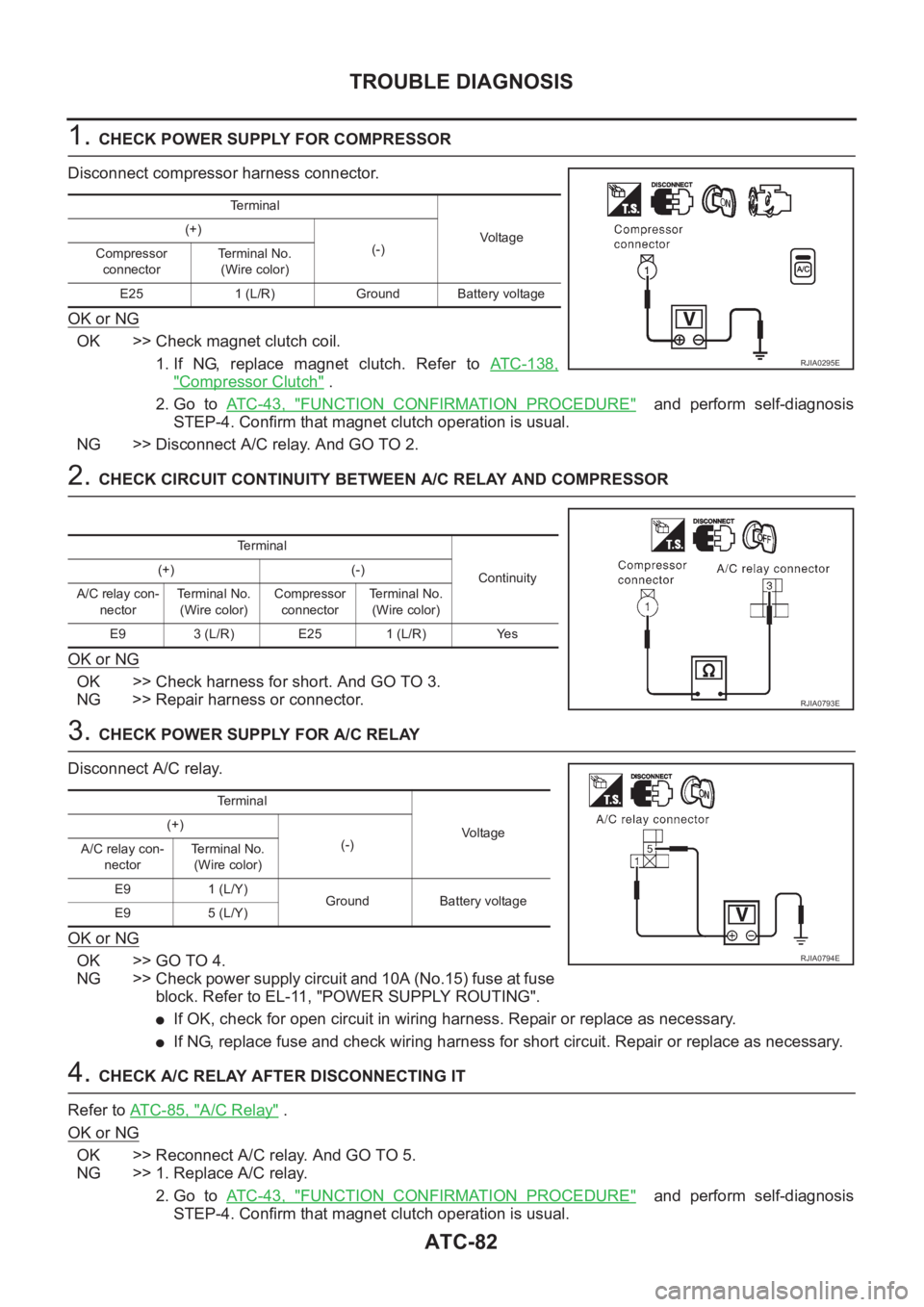
ATC-82
TROUBLE DIAGNOSIS
1. CHECK POWER SUPPLY FOR COMPRESSOR
Disconnect compressor harness connector.
OK or NG
OK >> Check magnet clutch coil.
1. If NG, replace magnet clutch. Refer to ATC-138,
"Compressor Clutch" .
2. Go to AT C - 4 3 , "
FUNCTION CONFIRMATION PROCEDURE" and perform self-diagnosis
STEP-4. Confirm that magnet clutch operation is usual.
NG >> Disconnect A/C relay. And GO TO 2.
2. CHECK CIRCUIT CONTINUITY BETWEEN A/C RELAY AND COMPRESSOR
OK or NG
OK >> Check harness for short. And GO TO 3.
NG >> Repair harness or connector.
3. CHECK POWER SUPPLY FOR A/C RELAY
Disconnect A/C relay.
OK or NG
OK >> GO TO 4.
NG >> Check power supply circuit and 10A (No.15) fuse at fuse
block. Refer to EL-11, "POWER SUPPLY ROUTING".
●If OK, check for open circuit in wiring harness. Repair or replace as necessary.
●If NG, replace fuse and check wiring harness for short circuit. Repair or replace as necessary.
4. CHECK A/C RELAY AFTER DISCONNECTING IT
Refer to AT C - 8 5 , "
A/C Relay" .
OK or NG
OK >> Reconnect A/C relay. And GO TO 5.
NG >> 1. Replace A/C relay.
2. Go to AT C - 4 3 , "
FUNCTION CONFIRMATION PROCEDURE" and perform self-diagnosis
STEP-4. Confirm that magnet clutch operation is usual.
Te r m i n a l
Voltag e (+)
(-)
Compressor
connectorTerminal No.
(Wire color)
E25 1 (L/R) Ground Battery voltage
RJIA0295E
Terminal
Continuity (+) (-)
A/C relay con-
nectorTerminal No.
(Wire color)Compressor
connectorTe r m i n a l N o .
(Wire color)
E9 3 (L/R) E25 1 (L/R) Yes
RJIA0793E
Te r m i n a l
Voltage (+)
(-)
A/C relay con-
nectorTerminal No.
(Wire color)
E9 1 (L/Y)
Ground Battery voltage
E9 5 (L/Y)
RJIA0794E
Page 2382 of 3189
System DescriptionNJEL0351The headlamp system on vehicles for cold spec. option contains a daytime light unit. The unit activates the
following whenever the engine is running with the lighting switch in the OFF position:
Low beam headlamps
Parking, license, tail and illumination lamps
Power is supplied at all times
through 10A fuse (No. 38, located in the fusible link and fuse box)
to daytime light unit terminal 1 and
to lighting switch terminal 11.
Power is also supplied at all times
through 15A fuse (No. 36, located in the fusible link and fuse box)
to daytime light unit terminal 3 and
to lighting switch terminal 5.
Power is also supplied at all times
through 15A fuse (No. 35, located in the fusible link and fuse box)
to daytime light unit terminal 2 and
to lighting switch terminal 8.
With the ignition switch in the ON or START position, power is supplied
through 10A fuse [No. 20, located in the fuse block (J/B)]
to daytime light unit terminal 7.
With the ignition switch in the START position, power is supplied
through 10A fuse [No. 21, located in the fuse block (J/B)]
to daytime light unit terminal 6.
Ground is supplied to daytime light unit terminal 9 through body grounds E30 and E73.
HEADLAMP OPERATION (DAYTIME LIGHT CANCEL OPERATION)NJEL0351S01When the lighting switch is turned to the 1st or 2nd position, power is supplied
through lighting switch terminal 12,
to daytime light unit terminal 11.
Then daytime light will be canceled. And the lighting system operation will be the same as no daytime light
system.
DAYTIME LIGHT OPERATIONNJEL0351S02With the engine running and the lighting switch in the OFF position, power is supplied
from alternator terminal 3
to daytime light unit terminal 8,
through daytime light unit terminal 5
to terminal 4 of headlamp LH,
through daytime light unit terminal 4
to terminal 2 of headlamp RH and
through daytime light unit terminal 10
to tail lamp and illumination.
Ground is supplied to terminal 5 of headlamp LH and terminal 1 of headlamp RHthrough body grounds E30
and E73.
HEADLAMP — DAYTIME LIGHT SYSTEM —
System Description
EL-46