fuel cap release NISSAN ALMERA N16 2003 Electronic Repair Manual
[x] Cancel search | Manufacturer: NISSAN, Model Year: 2003, Model line: ALMERA N16, Model: NISSAN ALMERA N16 2003Pages: 3189, PDF Size: 54.76 MB
Page 349 of 3189
![NISSAN ALMERA N16 2003 Electronic Repair Manual PREPARATION
EC-19
[QG (WITH EURO-OBD)]
C
D
E
F
G
H
I
J
K
L
MA
EC
PREPARATIONPFP:00002
Special Service ToolsEBS00K2Z
Commercial Service ToolsEBS00K30
Tool number
Tool nameDescription
KV10117100
Heated NISSAN ALMERA N16 2003 Electronic Repair Manual PREPARATION
EC-19
[QG (WITH EURO-OBD)]
C
D
E
F
G
H
I
J
K
L
MA
EC
PREPARATIONPFP:00002
Special Service ToolsEBS00K2Z
Commercial Service ToolsEBS00K30
Tool number
Tool nameDescription
KV10117100
Heated](/img/5/57350/w960_57350-348.png)
PREPARATION
EC-19
[QG (WITH EURO-OBD)]
C
D
E
F
G
H
I
J
K
L
MA
EC
PREPARATIONPFP:00002
Special Service ToolsEBS00K2Z
Commercial Service ToolsEBS00K30
Tool number
Tool nameDescription
KV10117100
Heated oxygen
sensor wrenchLoosening or tightening heated oxygen sensors
with 22 mm (0.87 in) hexagon nut
KV10114400
Heated oxygen
sensor wrenchLoosening or tightening heated oxygen sensors
a: 22 mm (0.87 in)
KV109E0010
Break-out boxMeasuring the ECM signals with a circuit tester
KV109E0080
Y-cable adapterMeasuring the ECM signals with a circuit tester
S-NT379
S-NT636
S-NT825
S-NT826
Tool name Description
Quick connector
releaseRemoving fuel tube quick connectors in engine
room
(Available in SEC. 164 of PARTS CATALOG: Part
No. 16441 6N210)
Fuel filler cap adapter Checking fuel tank vacuum relief valve opening
pressure
PBIC0198E
S-NT653
Page 576 of 3189
![NISSAN ALMERA N16 2003 Electronic Repair Manual EC-246
[QG (WITH EURO-OBD)]
DTC P0420 THREE WAY CATALYST FUNCTION
DTC P0420 THREE WAY CATALYST FUNCTION
PFP:20905
On Board Diagnosis LogicEBS00K8J
The ECM monitors the switching frequency ratio of hea NISSAN ALMERA N16 2003 Electronic Repair Manual EC-246
[QG (WITH EURO-OBD)]
DTC P0420 THREE WAY CATALYST FUNCTION
DTC P0420 THREE WAY CATALYST FUNCTION
PFP:20905
On Board Diagnosis LogicEBS00K8J
The ECM monitors the switching frequency ratio of hea](/img/5/57350/w960_57350-575.png)
EC-246
[QG (WITH EURO-OBD)]
DTC P0420 THREE WAY CATALYST FUNCTION
DTC P0420 THREE WAY CATALYST FUNCTION
PFP:20905
On Board Diagnosis LogicEBS00K8J
The ECM monitors the switching frequency ratio of heated oxygen
sensors 1 and 2.
A three way catalyst (Manifold) with high oxygen storage capacity
will indicate a low switching frequency of heated oxygen sensor 2.
As oxygen storage capacity decreases, the heated oxygen sensor 2
switching frequency will increase.
When the frequency ratio of heated oxygen sensors 1 and 2
approaches a specified limit value, the three way catalyst (Manifold)
malfunction is diagnosed.
DTC Confirmation ProcedureEBS00K8K
NOTE:
If “DTC Confirmation Procedure” has been previously conducted, always turn ignition switch “OFF” and wait at
least 10 seconds before conducting the next test.
WITH CONSULT-II
TESTING CONDITION:
●Open engine hood before conducting the following procedure.
●Do not hold engine speed for more than the specified minutes below.
1. Start engine and warm it up to the normal operating temperature.
2. Turn ignition switch ″OFF″ and wait at least 10 seconds.
3. Start engine and keep the engine speed between 3,500 and 4,000 rpm for at least one minute under no
load.
4. Let engine idle for one minute.
5. Select “DTC & SRT CONFIRMATION” then “SRT WORK SUP-
PORT” mode with CONSULT-II.
6. Rev engine up to 2,500 to 3,500 rpm and hold it for 3 consecu-
tive minutes then release the accelerator pedal completely.
If “INCMP” of “CATALYST” changed to “COMPLT”, go to step 9
7. Wait 5 seconds at idle.
SEF484YF
DTC No. Trouble diagnosis name DTC detecting condition Possible cause
P0420
0420Catalyst system efficiency
below threshold
●Three way catalyst (Manifold) does not operate
properly.
●Three way catalyst (Manifold) does not have
enough oxygen storage capacity.
●Three way catalyst (Manifold)
●Exhaust tube
●Intake air leaks
●Fuel injectors
●Fuel injector leaks
●Spark plug
●Improper ignition timing
PBIB0566E
Page 743 of 3189
![NISSAN ALMERA N16 2003 Electronic Repair Manual PREPARATION
EC-413
[QG (WITHOUT EURO-OBD)]
C
D
E
F
G
H
I
J
K
L
MA
EC
PREPARATIONPFP:00002
Special Service ToolsEBS00KE6
Commercial Service ToolsEBS00KE7
Tool number
Tool nameDescription
KV10117100
Hea NISSAN ALMERA N16 2003 Electronic Repair Manual PREPARATION
EC-413
[QG (WITHOUT EURO-OBD)]
C
D
E
F
G
H
I
J
K
L
MA
EC
PREPARATIONPFP:00002
Special Service ToolsEBS00KE6
Commercial Service ToolsEBS00KE7
Tool number
Tool nameDescription
KV10117100
Hea](/img/5/57350/w960_57350-742.png)
PREPARATION
EC-413
[QG (WITHOUT EURO-OBD)]
C
D
E
F
G
H
I
J
K
L
MA
EC
PREPARATIONPFP:00002
Special Service ToolsEBS00KE6
Commercial Service ToolsEBS00KE7
Tool number
Tool nameDescription
KV10117100
Heated oxygen
sensor wrenchLoosening or tightening heated oxygen sensors
with 22 mm (0.87 in) hexagon nut
KV10114400
Heated oxygen
sensor wrenchLoosening or tightening heated oxygen sensors
a: 22 mm (0.87 in)
KV109E0010
Break-out boxMeasuring ECM signals with a circuit tester
KV109E0080
Y-cable adapterMeasuring ECM signals with a circuit tester
S-NT379
S-NT636
S-NT825
S-NT826
Tool name Description
Quick connector
releaseRemoving fuel tube quick connectors in engine
room
(Available in SEC. 164 of PARTS CATALOG: Part
No. 16441 6N210)
Fuel filler cap adapter Checking fuel tank vacuum relief valve opening
pressure
PBIC0198E
S-NT653
Page 1273 of 3189

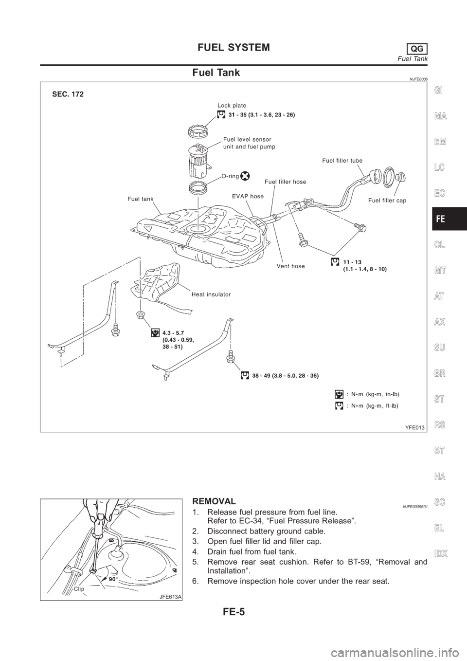
Fuel TankNJFE0006
YFE013
JFE613A
REMOVALNJFE0006S011. Release fuel pressure from fuel line.
Refer to EC-34, “Fuel Pressure Release”.
2. Disconnect battery ground cable.
3. Open fuel filler lid and filler cap.
4. Drain fuel from fuel tank.
5. Remove rear seat cushion. Refer to BT-59, “Removal and
Installation”.
6. Remove inspection hole cover under the rear seat.
GI
MA
EM
LC
EC
CL
MT
AT
AX
SU
BR
ST
RS
BT
HA
SC
EL
IDX
FUEL SYSTEMQG
Fuel Tank
FE-5
Page 1276 of 3189

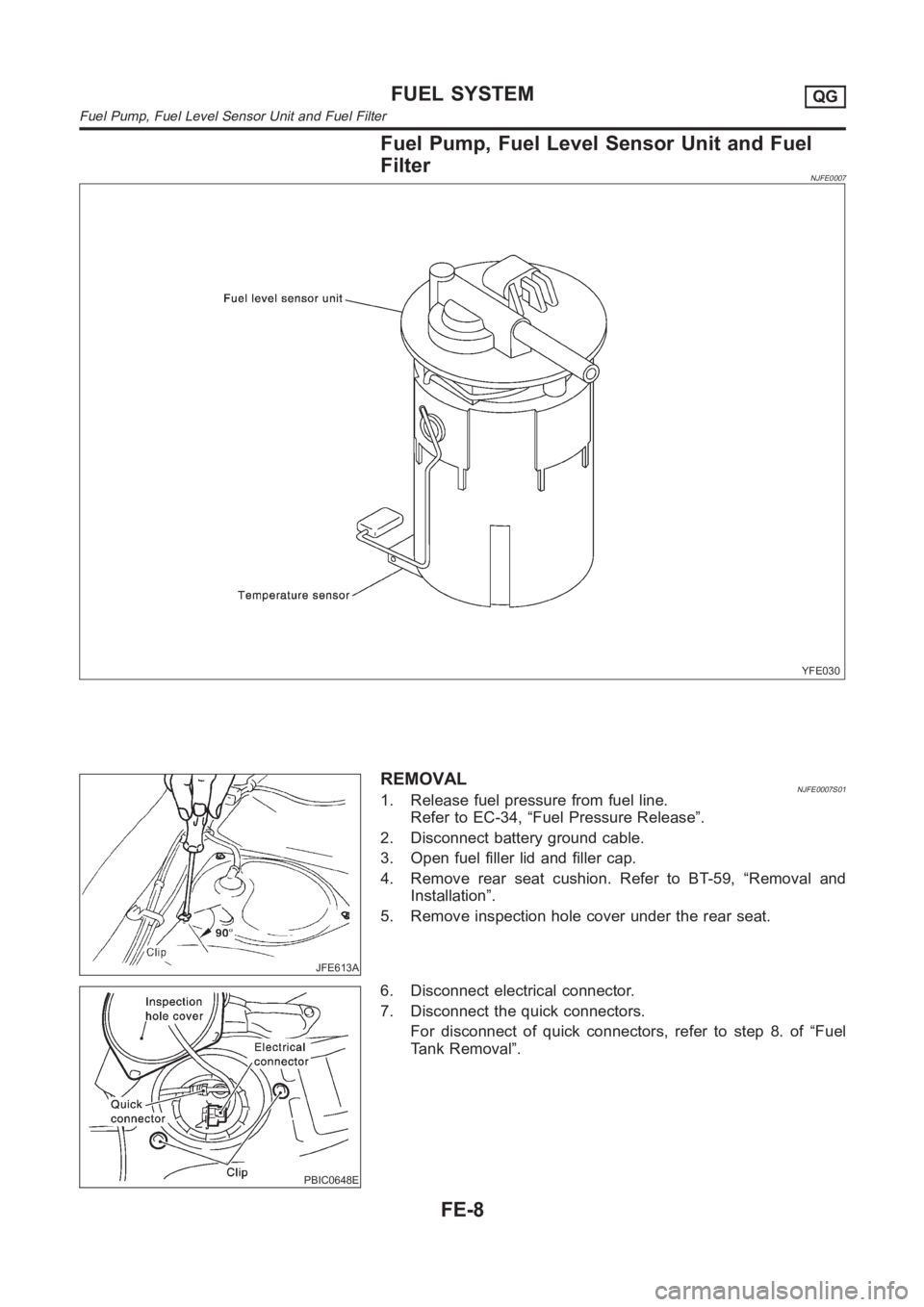
Fuel Pump, Fuel Level Sensor Unit and Fuel
Filter
NJFE0007
YFE030
JFE613A
REMOVALNJFE0007S011. Release fuel pressure from fuel line.
Refer to EC-34, “Fuel Pressure Release”.
2. Disconnect battery ground cable.
3. Open fuel filler lid and filler cap.
4. Remove rear seat cushion. Refer to BT-59, “Removal and
Installation”.
5. Remove inspection hole cover under the rear seat.
PBIC0648E
6. Disconnect electrical connector.
7. Disconnect the quick connectors.
For disconnect of quick connectors, refer to step 8. of “Fuel
Tank Removal”.
FUEL SYSTEMQG
Fuel Pump, Fuel Level Sensor Unit and Fuel Filter
FE-8