fuse block NISSAN ALMERA N16 2003 Electronic Service Manual
[x] Cancel search | Manufacturer: NISSAN, Model Year: 2003, Model line: ALMERA N16, Model: NISSAN ALMERA N16 2003Pages: 3189, PDF Size: 54.76 MB
Page 2442 of 3189
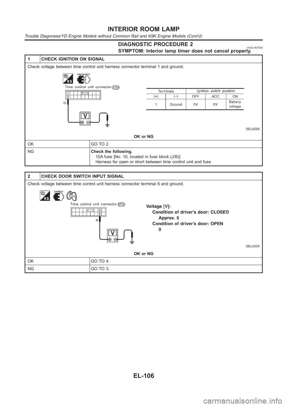
DIAGNOSTIC PROCEDURE 2=NJEL0437S02SYMPTOM: Interior lamp timer does not cancel properly.
1 CHECK IGNITION ON SIGNAL
Check voltage between time control unit harness connector terminal 1 and ground.
SEL429X
OK or NG
OK GO TO 2.
NGCheck the following.
10A fuse [No. 10, located in fuse block (J/B)]
Harness for open or short between time control unit and fuse
2 CHECK DOOR SWITCH INPUT SIGNAL
Check voltage between time control unit harness connector terminal 6 and ground.
SEL430X
OK or NG
OK GO TO 4.
NG GO TO 3.
INTERIOR ROOM LAMP
Trouble Diagnoses/YD Engine Models without Common Rail and K9K Engine Models (Cont’d)
EL-106
Page 2446 of 3189
Component Parts and Harness Connector
Location
NJEL0441For details, refer to “ELECTRICAL UNIT LOCATION” (EL-543) and
“HARNESS LAYOUT” (EL-550).
System DescriptionNJEL0442UNIFIED CONTROL METERNJEL0442S01Speedometer, odo/trip meter, tachometer, fuel gauge and water temperature gauge are controlled totally
by control unit built-in combination meter.
Digital meter is adopted for odo/trip meter.*
*The record of the odo meter is kept even if the battery cable is disconnected. The record of the trip meter
is erased when the battery cable is disconnected.
Odo/trip meter segment can be checked in diagnosis mode.
Meter/gauge can be checked in diagnosis mode.
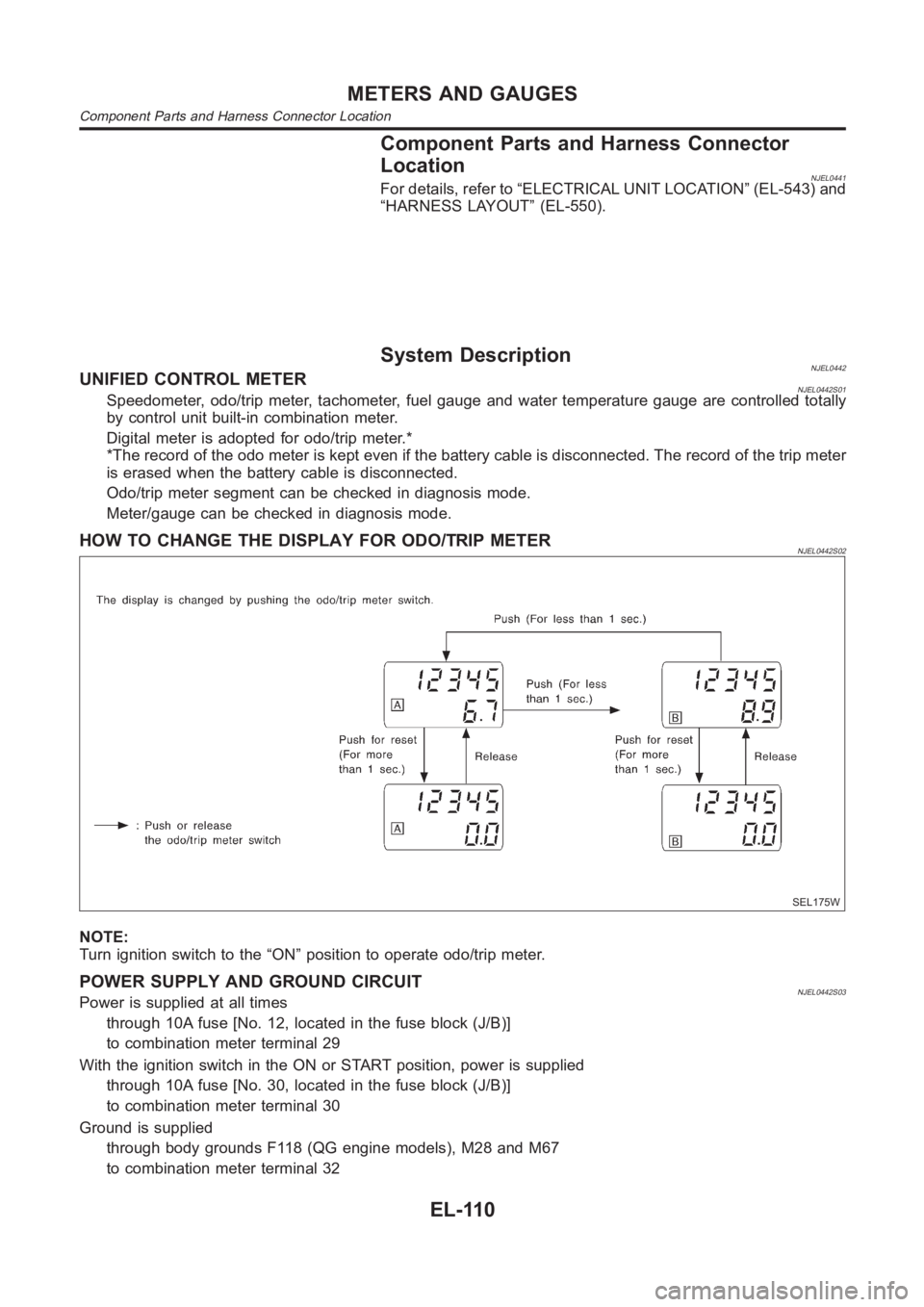
HOW TO CHANGE THE DISPLAY FOR ODO/TRIP METERNJEL0442S02
SEL175W
NOTE:
Turn ignition switch to the “ON” position to operate odo/trip meter.
POWER SUPPLY AND GROUND CIRCUITNJEL0442S03Power is supplied at all times
through 10A fuse [No. 12, located in the fuse block (J/B)]
to combination meter terminal 29
With the ignition switch in the ON or START position, power is supplied
through 10A fuse [No. 30, located in the fuse block (J/B)]
to combination meter terminal 30
Ground is supplied
through body grounds F118 (QG engine models), M28 and M67
to combination meter terminal 32
METERS AND GAUGES
Component Parts and Harness Connector Location
EL-110
Page 2458 of 3189
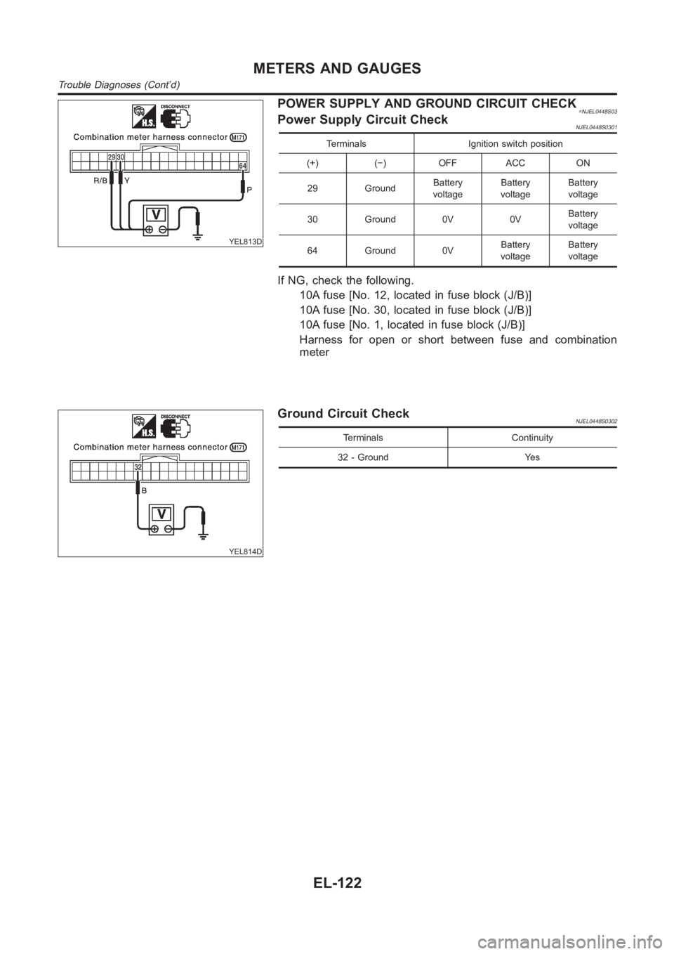
YEL813D
POWER SUPPLY AND GROUND CIRCUIT CHECK=NJEL0448S03Power Supply Circuit CheckNJEL0448S0301
Terminals Ignition switch position
(+) (−) OFF ACC ON
29 GroundBattery
voltageBattery
voltageBattery
voltage
30 Ground 0V 0VBattery
voltage
64 Ground 0VBattery
voltageBattery
voltage
If NG, check the following.
10A fuse [No. 12, located in fuse block (J/B)]
10A fuse [No. 30, located in fuse block (J/B)]
10A fuse [No. 1, located in fuse block (J/B)]
Harness for open or short between fuse and combination
meter
YEL814D
Ground Circuit CheckNJEL0448S0302
Terminals Continuity
32 - Ground Yes
METERS AND GAUGES
Trouble Diagnoses (Cont’d)
EL-122
Page 2472 of 3189
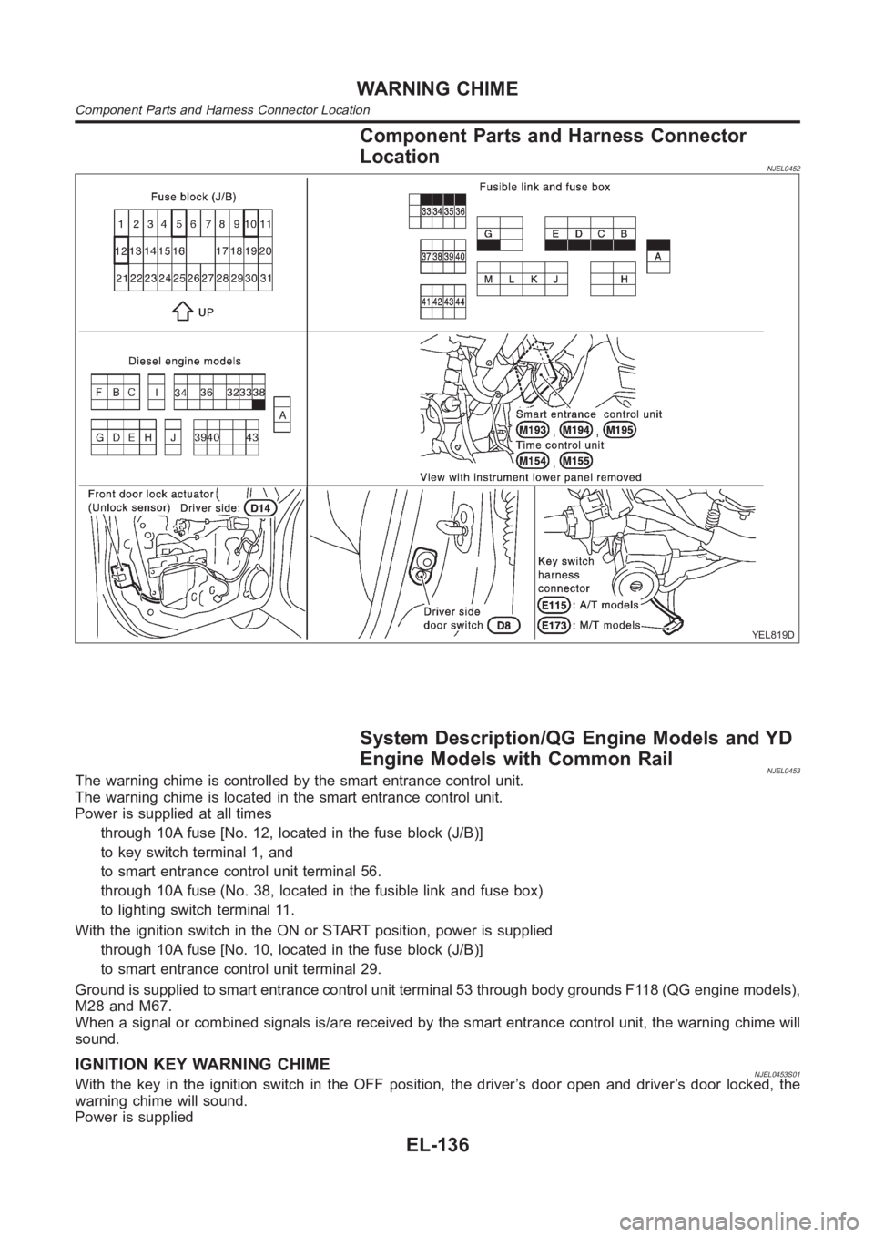
Component Parts and Harness Connector
Location
NJEL0452
YEL819D
System Description/QG Engine Models and YD
Engine Models with Common Rail
NJEL0453The warning chime is controlled by the smart entrance control unit.
The warning chime is located in the smart entrance control unit.
Power is supplied at all times
through 10A fuse [No. 12, located in the fuse block (J/B)]
to key switch terminal 1, and
to smart entrance control unit terminal 56.
through 10A fuse (No. 38, located in the fusible link and fuse box)
to lighting switch terminal 11.
With the ignition switch in the ON or START position, power is supplied
through 10A fuse [No. 10, located in the fuse block (J/B)]
to smart entrance control unit terminal 29.
Ground is supplied to smart entrance control unit terminal 53 through bodygrounds F118 (QG engine models),
M28 and M67.
When a signal or combined signals is/are received by the smart entrance control unit, the warning chime will
sound.
IGNITION KEY WARNING CHIMENJEL0453S01With the key in the ignition switch in the OFF position, the driver’s door open and driver’s door locked, the
warning chime will sound.
Power is supplied
WARNING CHIME
Component Parts and Harness Connector Location
EL-136
Page 2473 of 3189
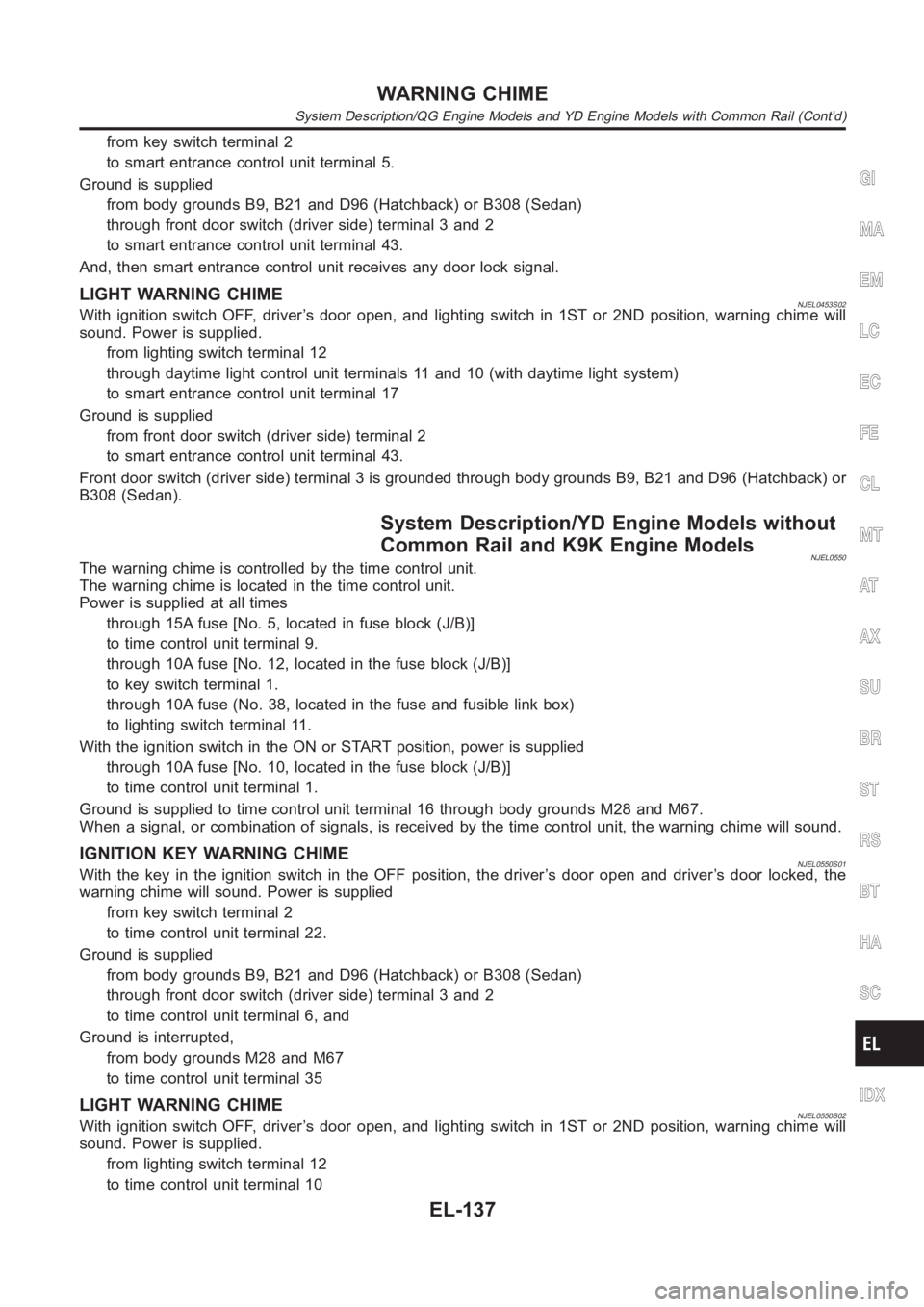
from key switch terminal 2
to smart entrance control unit terminal 5.
Ground is supplied
from body grounds B9, B21 and D96 (Hatchback) or B308 (Sedan)
through front door switch (driver side) terminal 3 and 2
to smart entrance control unit terminal 43.
And, then smart entrance control unit receives any door lock signal.
LIGHT WARNING CHIMENJEL0453S02With ignition switch OFF, driver’s door open, and lighting switch in 1ST or2ND position, warning chime will
sound. Power is supplied.
from lighting switch terminal 12
through daytime light control unit terminals 11 and 10 (with daytime lightsystem)
to smart entrance control unit terminal 17
Ground is supplied
from front door switch (driver side) terminal 2
to smart entrance control unit terminal 43.
Front door switch (driver side) terminal 3 is grounded through body grounds B9, B21 and D96 (Hatchback) or
B308 (Sedan).
System Description/YD Engine Models without
Common Rail and K9K Engine Models
NJEL0550The warning chime is controlled by the time control unit.
The warning chime is located in the time control unit.
Power is supplied at all times
through 15A fuse [No. 5, located in fuse block (J/B)]
to time control unit terminal 9.
through 10A fuse [No. 12, located in the fuse block (J/B)]
to key switch terminal 1.
through 10A fuse (No. 38, located in the fuse and fusible link box)
to lighting switch terminal 11.
With the ignition switch in the ON or START position, power is supplied
through 10A fuse [No. 10, located in the fuse block (J/B)]
to time control unit terminal 1.
Ground is supplied to time control unit terminal 16 through body grounds M28 and M67.
When a signal, or combination of signals, is received by the time control unit, the warning chime will sound.
IGNITION KEY WARNING CHIMENJEL0550S01With the key in the ignition switch in the OFF position, the driver’s door open and driver’s door locked, the
warning chime will sound. Power is supplied
from key switch terminal 2
to time control unit terminal 22.
Ground is supplied
from body grounds B9, B21 and D96 (Hatchback) or B308 (Sedan)
through front door switch (driver side) terminal 3 and 2
to time control unit terminal 6, and
Ground is interrupted,
from body grounds M28 and M67
to time control unit terminal 35
LIGHT WARNING CHIMENJEL0550S02With ignition switch OFF, driver’s door open, and lighting switch in 1ST or2ND position, warning chime will
sound. Power is supplied.
from lighting switch terminal 12
to time control unit terminal 10
GI
MA
EM
LC
EC
FE
CL
MT
AT
AX
SU
BR
ST
RS
BT
HA
SC
IDX
WARNING CHIME
System Description/QG Engine Models and YD Engine Models with Common Rail(Cont’d)
EL-137
Page 2479 of 3189
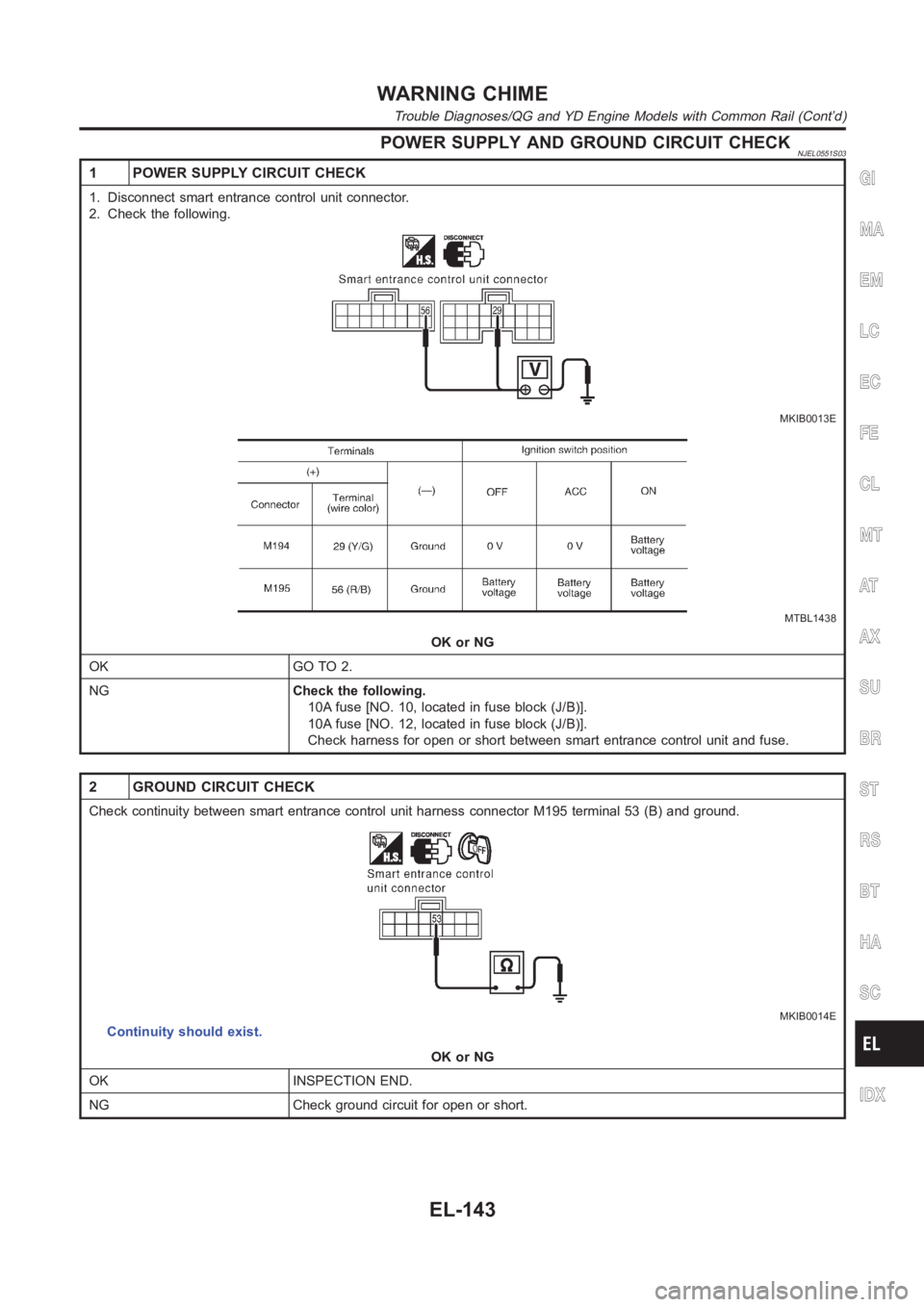
POWER SUPPLY AND GROUND CIRCUIT CHECKNJEL0551S03
1 POWER SUPPLY CIRCUIT CHECK
1. Disconnect smart entrance control unit connector.
2. Check the following.
MKIB0013E
MTBL1438
OK or NG
OK GO TO 2.
NGCheck the following.
10A fuse [NO. 10, located in fuse block (J/B)].
10A fuse [NO. 12, located in fuse block (J/B)].
Check harness for open or short between smart entrance control unit and fuse.
2 GROUND CIRCUIT CHECK
Check continuity between smart entrance control unit harness connector M195 terminal 53 (B) and ground.
MKIB0014E
Continuity should exist.
OK or NG
OK INSPECTION END.
NG Check ground circuit for open or short.
GI
MA
EM
LC
EC
FE
CL
MT
AT
AX
SU
BR
ST
RS
BT
HA
SC
IDX
WARNING CHIME
Trouble Diagnoses/QG and YD Engine Models with Common Rail (Cont’d)
EL-143
Page 2484 of 3189
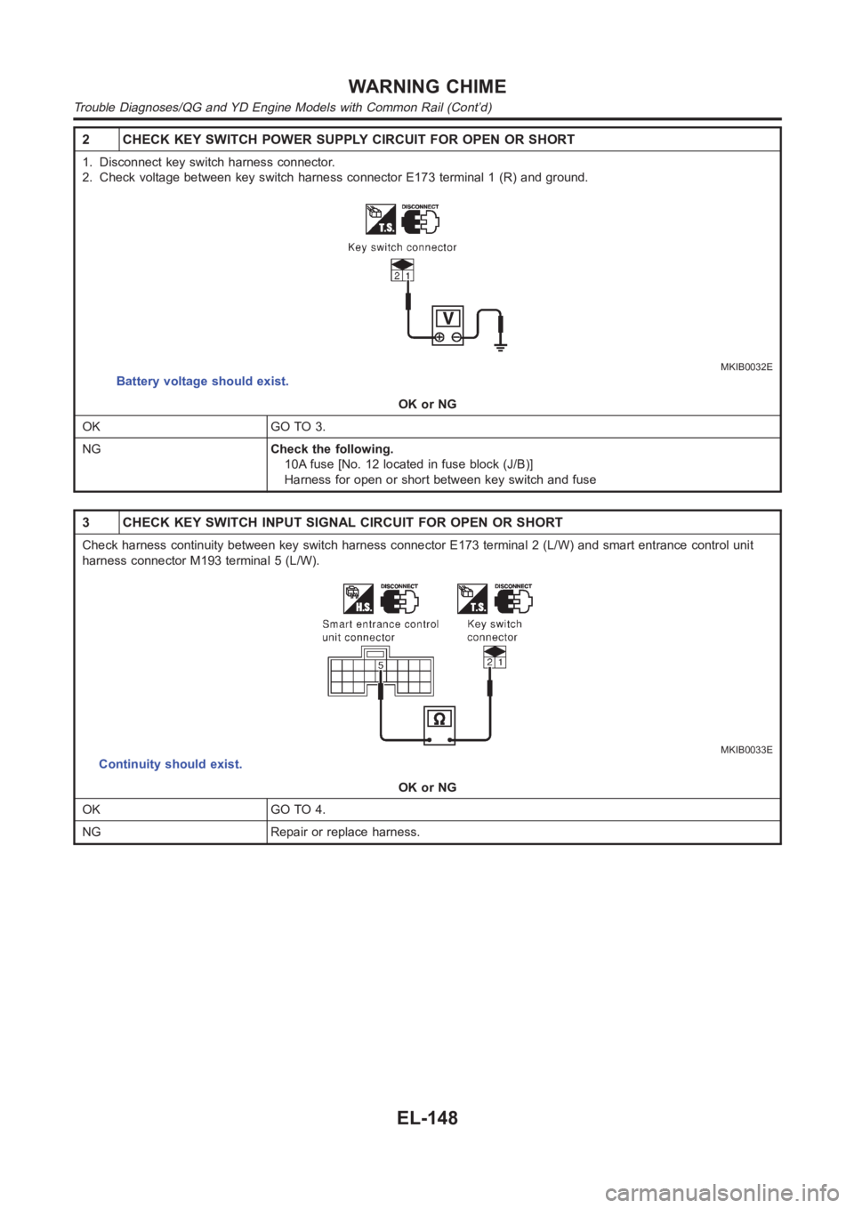
2 CHECK KEY SWITCH POWER SUPPLY CIRCUIT FOR OPEN OR SHORT
1. Disconnect key switch harness connector.
2. Check voltage between key switch harness connector E173 terminal 1 (R) and ground.
MKIB0032E
Battery voltage should exist.
OK or NG
OK GO TO 3.
NGCheck the following.
10A fuse [No. 12 located in fuse block (J/B)]
Harness for open or short between key switch and fuse
3 CHECK KEY SWITCH INPUT SIGNAL CIRCUIT FOR OPEN OR SHORT
Check harness continuity between key switch harness connector E173 terminal 2 (L/W) and smart entrance control unit
harness connector M193 terminal 5 (L/W).
MKIB0033E
Continuity should exist.
OK or NG
OK GO TO 4.
NG Repair or replace harness.
WARNING CHIME
Trouble Diagnoses/QG and YD Engine Models with Common Rail (Cont’d)
EL-148
Page 2490 of 3189
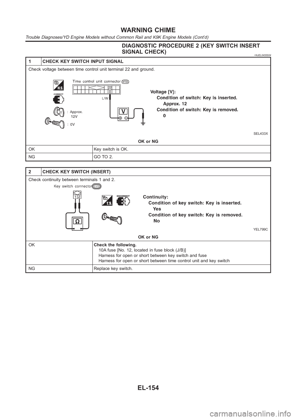
DIAGNOSTIC PROCEDURE 2 (KEY SWITCH INSERT
SIGNAL CHECK)
=NJEL0455S04
1 CHECK KEY SWITCH INPUT SIGNAL
Check voltage between time control unit terminal 22 and ground.
SEL433X
OK or NG
OK Key switch is OK.
NG GO TO 2.
2 CHECK KEY SWITCH (INSERT)
Check continuity between terminals 1 and 2.
YEL799C
OK or NG
OKCheck the following.
10A fuse [No. 12, located in fuse block (J/B)]
Harness for open or short between key switch and fuse
Harness for open or short between time control unit and key switch
NG Replace key switch.
WARNING CHIME
Trouble Diagnoses/YD Engine Models without Common Rail and K9K Engine Models (Cont’d)
EL-154
Page 2492 of 3189
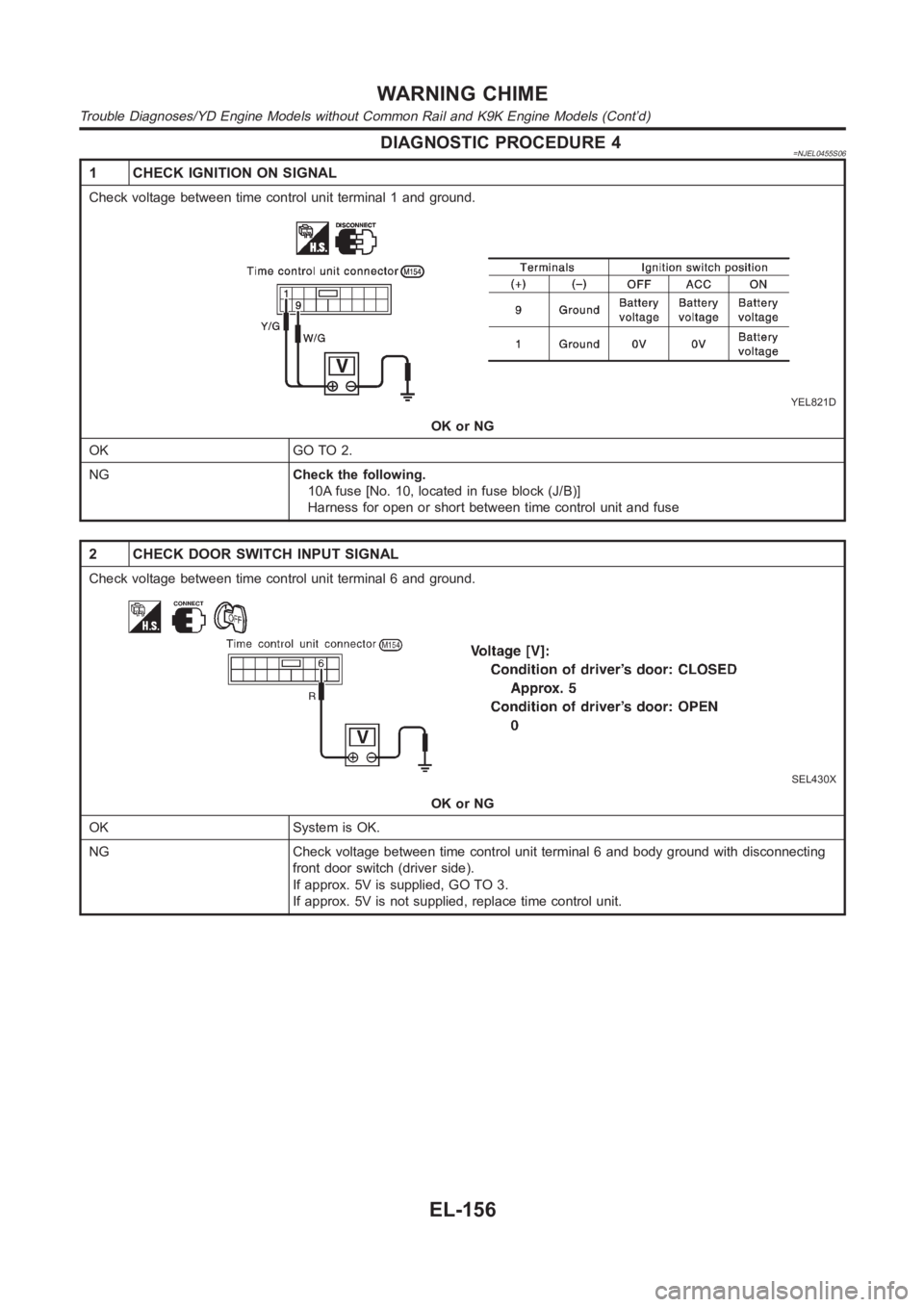
DIAGNOSTIC PROCEDURE 4=NJEL0455S06
1 CHECK IGNITION ON SIGNAL
Check voltage between time control unit terminal 1 and ground.
YEL821D
OK or NG
OK GO TO 2.
NGCheck the following.
10A fuse [No. 10, located in fuse block (J/B)]
Harness for open or short between time control unit and fuse
2 CHECK DOOR SWITCH INPUT SIGNAL
Check voltage between time control unit terminal 6 and ground.
SEL430X
OK or NG
OK System is OK.
NG Check voltage between time control unit terminal 6 and body ground with disconnecting
front door switch (driver side).
If approx. 5V is supplied, GO TO 3.
If approx. 5V is not supplied, replace time control unit.
WARNING CHIME
Trouble Diagnoses/YD Engine Models without Common Rail and K9K Engine Models (Cont’d)
EL-156
Page 2494 of 3189
System DescriptionNJEL0456WIPER OPERATIONNJEL0456S01The wiper switch is controlled by a lever built into the combination switch.
There are three wiper switch positions:
LO speed
HI speed
INT (Intermittent)
With the ignition switch in the ON or START position, power is supplied
through 20A fuse [No. 25, located in the fuse block (J/B)]
to front wiper motor terminal 5.
Low and High Speed Wiper OperationNJEL0456S0101Ground is supplied to wiper and washer switch terminal 17 through body grounds E30 and E73.
When the wiper switch is placed in the LO position, ground is supplied
through terminal 14 of the front wiper and washer switch
to front wiper motor terminal 2.
With power and ground supplied, the wiper motor operates at low speed.
When the wiper switch is placed in the HI position, ground is supplied
through terminal 16 of the front wiper and washer switch
to wiper motor terminal 1.
With power and ground supplied, the wiper motor operates at high speed.
Auto Stop OperationNJEL0456S0102With wiper switch turned OFF, wiper motor will continue to operate until wiper arms reach windshield base.
When wiper arms are not located at base of windshield with wiper switch OFF,ground is provided
from terminal 14 of the front wiper and washer switch
to front wiper motor terminal 2, in order to continue wiper motor operationat low speed.
Ground is also supplied
through terminal 13 of the front wiper and washer switch
to front wiper motor terminal 4
through terminal 3 of front wiper motor
through body grounds E30 and E73.
When wiper arms reach base of windshield, front wiper motor terminals 4 and5 are connected instead of ter-
minals 4 and 3. Wiper motor will then stop wiper arms at the STOP position.
Intermittent OperationNJEL0456S0103The front wiper motor operates the wiper arms one time at low speed at a set interval of approximately 1 to
13 seconds. This feature is controlled by the wiper amplifier (INT SW) combined with front wiper switch.
When the wiper switch is placed in the INT position, ground is supplied to wiper amplifier (WIPER SW INT)
and (ACC).
The desired interval time is input to wiper amplifier (INT VR) from wiper volume switch combined with front
wiper and washer switch.
When the wiper switch is placed in the INT position, intermittent ground issupplied
through wiper amplifier (OUTPUT) and
through terminal 14 of front wiper and washer switch
to front wiper motor terminal 5.
The wiper motor operates at low speed at the desired interval.
When the lever is pulled to the WASH position for one second or more, the wiper motor operates at low speed
for approximately 3 seconds to clean windshield. This feature is controlled by the wiper amplifier in the same
manner as the intermittent operation.
WASHER OPERATIONNJEL0456S02With the ignition switch in the ON or START position, power is supplied
through 10A fuse [No. 27, located in the fuse block (J/B)]
through front wiper switch terminals 15 and 18.
to front washer motor terminal 1.
FRONT WIPER AND WASHER
System Description
EL-158