NISSAN ALMERA N16 2003 Electronic Repair Manual
ALMERA N16 2003
NISSAN
NISSAN
https://www.carmanualsonline.info/img/5/57350/w960_57350-0.png
NISSAN ALMERA N16 2003 Electronic Repair Manual
Trending: maintenance schedule, door motor, fuse, Window Switch, steering, load capacity, tail lamp
Page 3121 of 3189
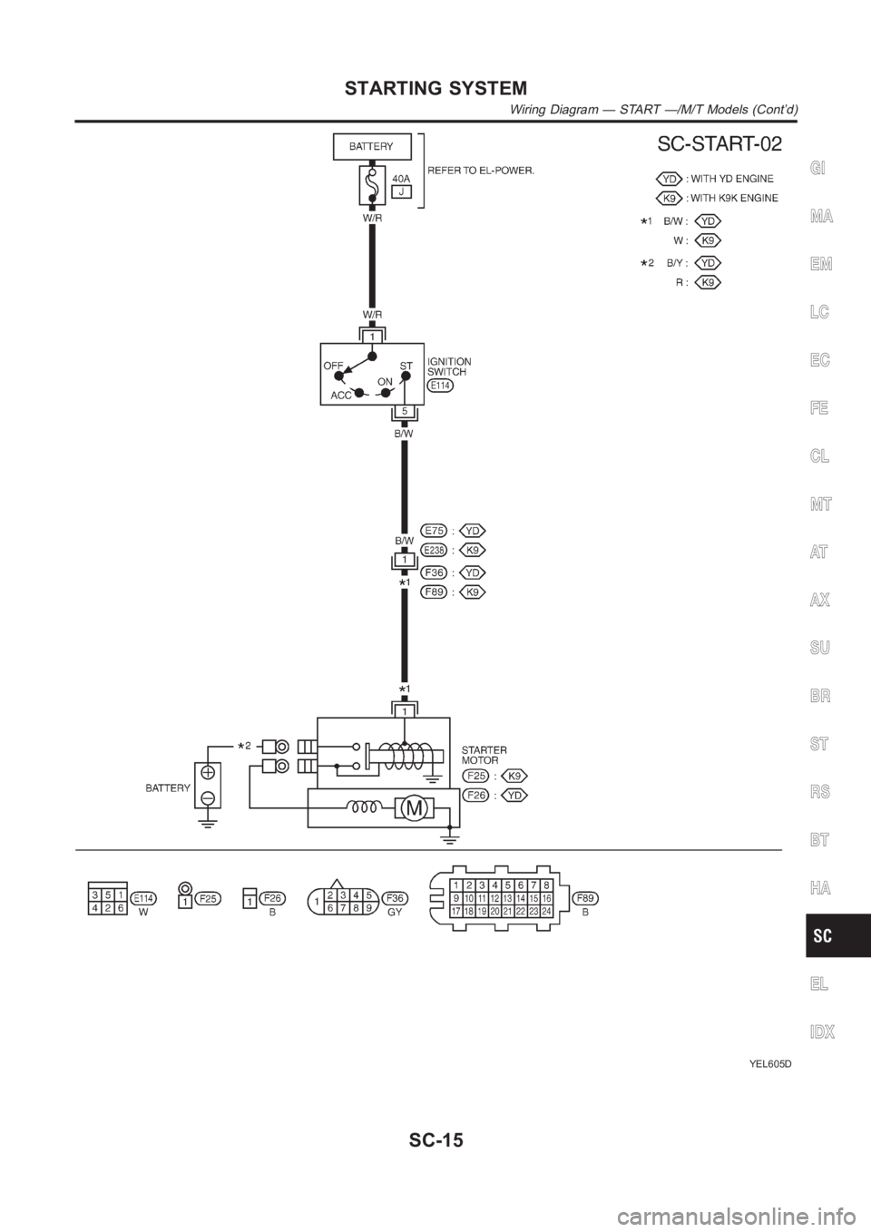
YEL605D
GI
MA
EM
LC
EC
FE
CL
MT
AT
AX
SU
BR
ST
RS
BT
HA
EL
IDX
STARTING SYSTEM
Wiring Diagram — START —/M/T Models (Cont’d)
SC-15
Page 3122 of 3189
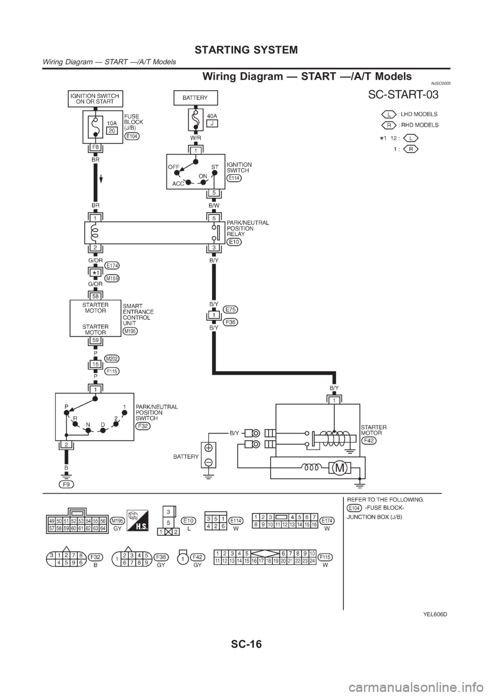
Wiring Diagram — START —/A/T ModelsNJSC0005
YEL606D
STARTING SYSTEM
Wiring Diagram — START —/A/T Models
SC-16
Page 3123 of 3189
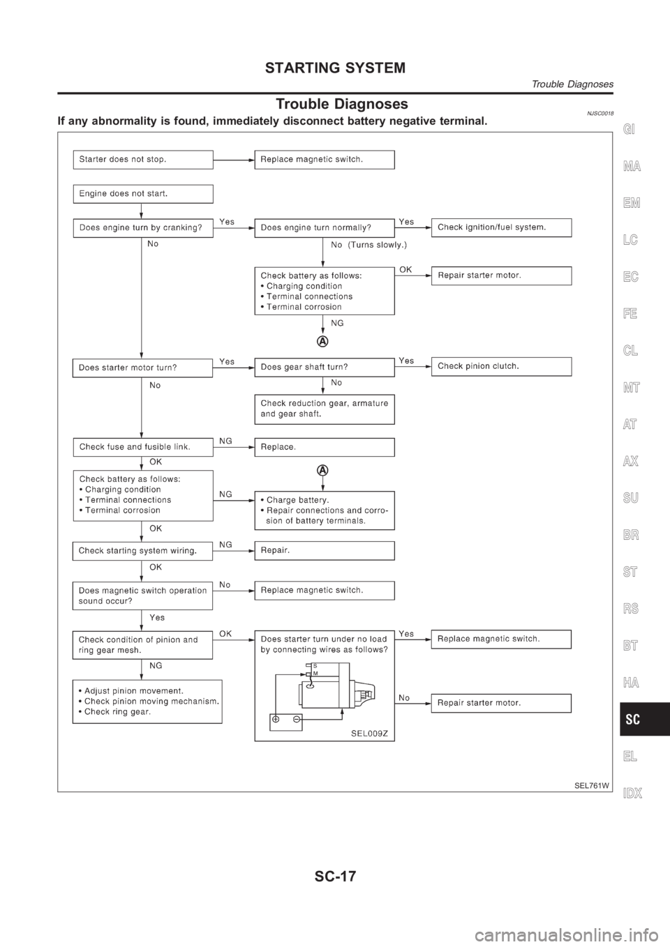
Trouble DiagnosesNJSC0018If any abnormality is found, immediately disconnect battery negative terminal.
SEL761W
GI
MA
EM
LC
EC
FE
CL
MT
AT
AX
SU
BR
ST
RS
BT
HA
EL
IDX
STARTING SYSTEM
Trouble Diagnoses
SC-17
Page 3124 of 3189
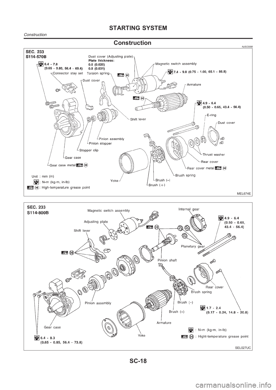
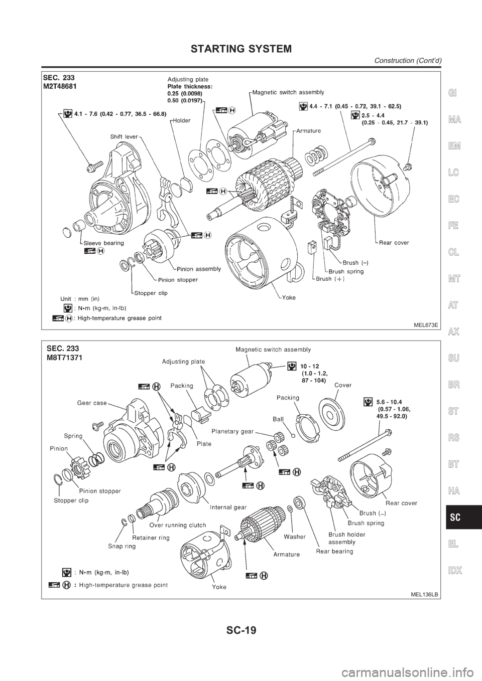
ConstructionNJSC0006
MEL674E
SEL027UC
STARTING SYSTEM
Construction
SC-18
Page 3125 of 3189
MEL673E
MEL136LB
GI
MA
EM
LC
EC
FE
CL
MT
AT
AX
SU
BR
ST
RS
BT
HA
EL
IDX
STARTING SYSTEM
Construction (Cont’d)
SC-19
Page 3126 of 3189
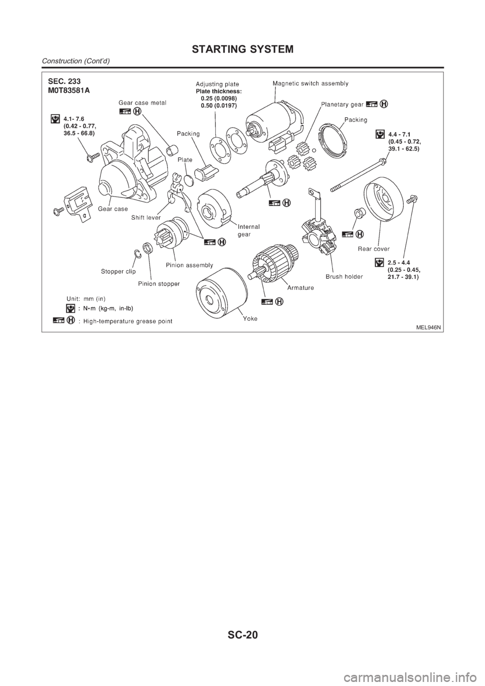
MEL946N
STARTING SYSTEM
Construction (Cont’d)
SC-20
Page 3127 of 3189
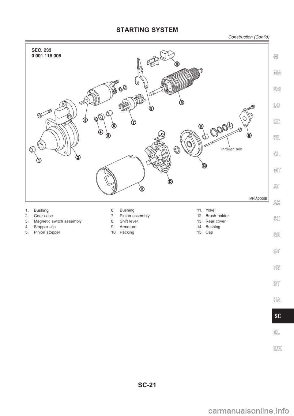
MKIA0009E
1. Bushing
2. Gear case
3. Magnetic switch assembly
4. Stopper clip
5. Pinion stopper6. Bushing
7. Pinion assembly
8. Shift lever
9. Armature
10. Packing11 . Yo k e
12. Brush holder
13. Rear cover
14. Bushing
15. Cap
GI
MA
EM
LC
EC
FE
CL
MT
AT
AX
SU
BR
ST
RS
BT
HA
EL
IDX
STARTING SYSTEM
Construction (Cont’d)
SC-21
Page 3128 of 3189
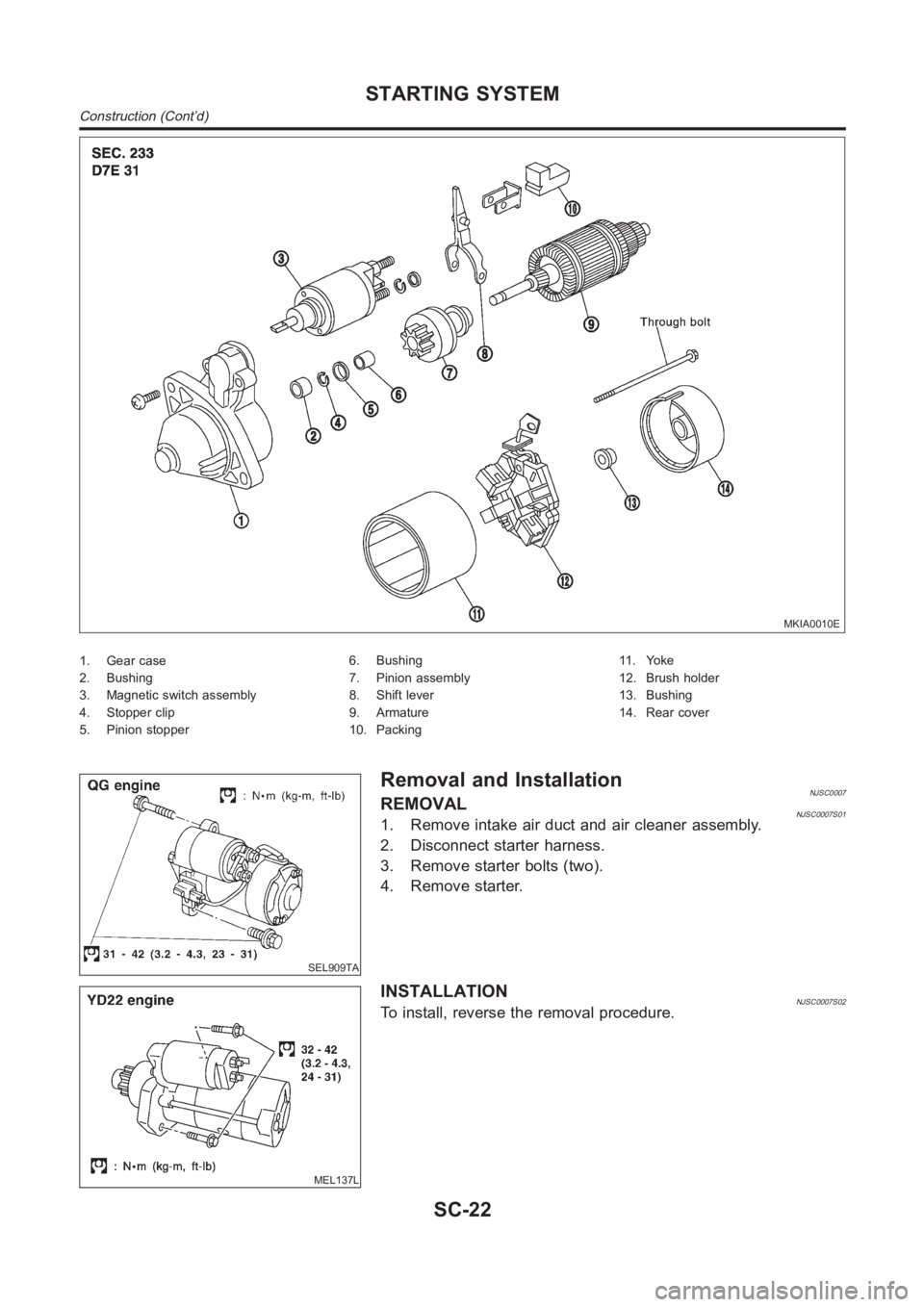
MKIA0010E
1. Gear case
2. Bushing
3. Magnetic switch assembly
4. Stopper clip
5. Pinion stopper6. Bushing
7. Pinion assembly
8. Shift lever
9. Armature
10. Packing11 . Yo k e
12. Brush holder
13. Bushing
14. Rear cover
SEL909TA
Removal and InstallationNJSC0007REMOVALNJSC0007S011. Remove intake air duct and air cleaner assembly.
2. Disconnect starter harness.
3. Remove starter bolts (two).
4. Remove starter.
MEL137L
INSTALLATIONNJSC0007S02To install, reverse the removal procedure.
STARTING SYSTEM
Construction (Cont’d)
SC-22
Page 3129 of 3189
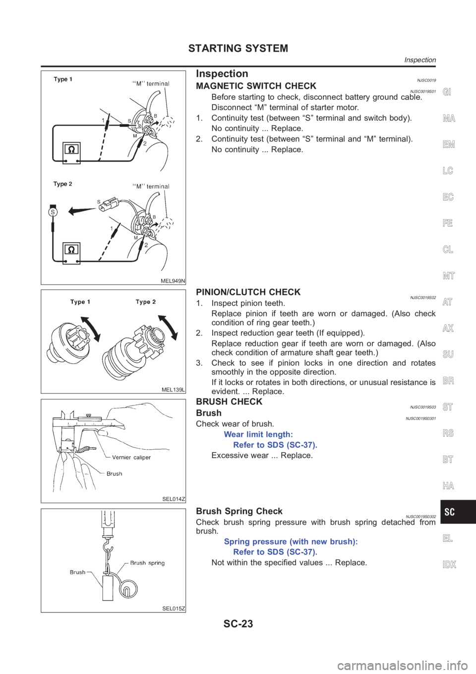
MEL949N
InspectionNJSC0019MAGNETIC SWITCH CHECKNJSC0019S01Before starting to check, disconnect battery ground cable.
Disconnect “M” terminal of starter motor.
1. Continuity test (between “S” terminal and switch body).
No continuity ... Replace.
2. Continuity test (between “S” terminal and “M” terminal).
No continuity ... Replace.
MEL139L
PINION/CLUTCH CHECKNJSC0019S021. Inspect pinion teeth.
Replace pinion if teeth are worn or damaged. (Also check
condition of ring gear teeth.)
2. Inspect reduction gear teeth (If equipped).
Replace reduction gear if teeth are worn or damaged. (Also
check condition of armature shaft gear teeth.)
3. Check to see if pinion locks in one direction and rotates
smoothly in the opposite direction.
If it locks or rotates in both directions, or unusual resistance is
evident. ... Replace.
SEL014Z
BRUSH CHECKNJSC0019S03BrushNJSC0019S0301Check wear of brush.
Wear limit length:
Refer to SDS (SC-37).
Excessive wear ... Replace.
SEL015Z
Brush Spring CheckNJSC0019S0302Check brush spring pressure with brush spring detached from
brush.
Spring pressure (with new brush):
Refer to SDS (SC-37).
Not within the specified values ... Replace.
GI
MA
EM
LC
EC
FE
CL
MT
AT
AX
SU
BR
ST
RS
BT
HA
EL
IDX
STARTING SYSTEM
Inspection
SC-23
Page 3130 of 3189
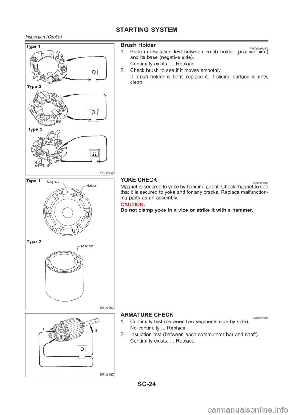
SEL016Z
Brush HolderNJSC0019S03031. Perform insulation test between brush holder (positive side)
and its base (negative side).
Continuity exists. ... Replace.
2. Check brush to see if it moves smoothly.
If brush holder is bent, replace it; if sliding surface is dirty,
clean.
SEL018Z
YOKE CHECKNJSC0019S04Magnet is secured to yoke by bonding agent. Check magnet to see
that it is secured to yoke and for any cracks. Replace malfunction-
ing parts as an assembly.
CAUTION:
Do not clamp yoke in a vice or strike it with a hammer.
SEL019Z
ARMATURE CHECKNJSC0019S051. Continuity test (between two segments side by side).
No continuity ... Replace.
2. Insulation test (between each commutator bar and shaft).
Continuity exists. ... Replace.
STARTING SYSTEM
Inspection (Cont’d)
SC-24
Trending: oil, sensor, Time, language, wheel, trip computer, trailer
