timing chain NISSAN ALMERA N16 2003 Electronic Service Manual
[x] Cancel search | Manufacturer: NISSAN, Model Year: 2003, Model line: ALMERA N16, Model: NISSAN ALMERA N16 2003Pages: 3189, PDF Size: 54.76 MB
Page 777 of 3189

TROUBLE DIAGNOSIS
EC-447
[QG (WITHOUT EURO-OBD)]
C
D
E
F
G
H
I
J
K
L
MA
EC
15.CHECK IGNITION TIMING AGAIN
1. Run engine at idle.
2. Check ignition timing with a timing light.
OK or NG
OK >>INSPECTION END
NG >> GO TO 16.
16.CHECK TIMING CHAIN INSTALLATION
Check timing chain installation. Refer to EM-47, "
TIMING CHAIN" .
OK or NG
OK >> GO TO 17.
NG >> 1. Repair the timing chain installation.
2. GO TO 4.
17.DETECT MALFUNCTIONING PART
Check the following.
●Check camshaft position sensor (PHASE) and circuit. Refer to EC-561 .
●Check crankshaft position sensor (POS) and circuit. Refer to EC-554 .
OK or NG
OK >> GO TO 18.
NG >> 1. Repair or replace.
2. GO TO 4.
18.CHECK ECM FUNCTION
1. Substitute another known-good ECM to check ECM function. (ECM may be the cause of a incident, but
this is the rarely the case.)
2. Perform initialization of NATS system and registration of NATS ignition key IDs. Refer to EC-431, "
NATS
(Nissan Anti-theft System)" .
>> GO TO 4. M/T: 8 ± 5° BTDC
A/T: 10 ± 5° BTDC (in “P” or “N” position)
Page 1018 of 3189

EC-688
[QG (WITHOUT EURO-OBD)]
IVT CONTROL SOLENOID VALVE
6. CHECK CRANKSHAFT POSITION SENSOR (POS)
Refer to EC-559, "
Component Inspection" .
OK or NG
OK >> GO TO 7.
NG >> Replace crankshaft position sensor (POS).
7. CHECK CAMSHAFT POSITION SENSOR (PHASE)
Refer to EC-566, "
Component Inspection" .
OK or NG
OK >> GO TO 8.
NG >> Replace camshaft position sensor (PHASE).
8. CHECK CAMSHAFT (INTAKE)
Check the following.
●Accumulation of debris to the signal plate of camshaft rear end
●Chipping signal plate of camshaft rear end
OK or NG
OK >> GO TO 9.
NG >> Remove debris and clean the signal plate of camshaft
rear end or replace camshaft.
9. CHECK INTERMITTENT INCIDENT
Refer to EC-485, "
TROUBLE DIAGNOSIS FOR INTERMITTENT INCIDENT" .
>>INSPECTION END
Component InspectionEBS00KLP
INTAKE VALVE TIMING CONTROL SOLENOID VALVE
1. Disconnect intake valve timing control solenoid valve harness connector.
2. Check resistance between intake valve timing control solenoid
valve terminals 1 and 2.
Removal and InstallationEBS00KLQ
INTAKE VALVE TIMING CONTROL SOLENOID VALVE
Refer to EM-47, "TIMING CHAIN" .
PBIB0565E
Terminals Resistance
1 and 2 Approximately 8Ω at 20°C (68°F)
1 or 2 and ground∞Ω
(Continuity should not exist)
PBIB0574E
Page 1080 of 3189
JEF351Y
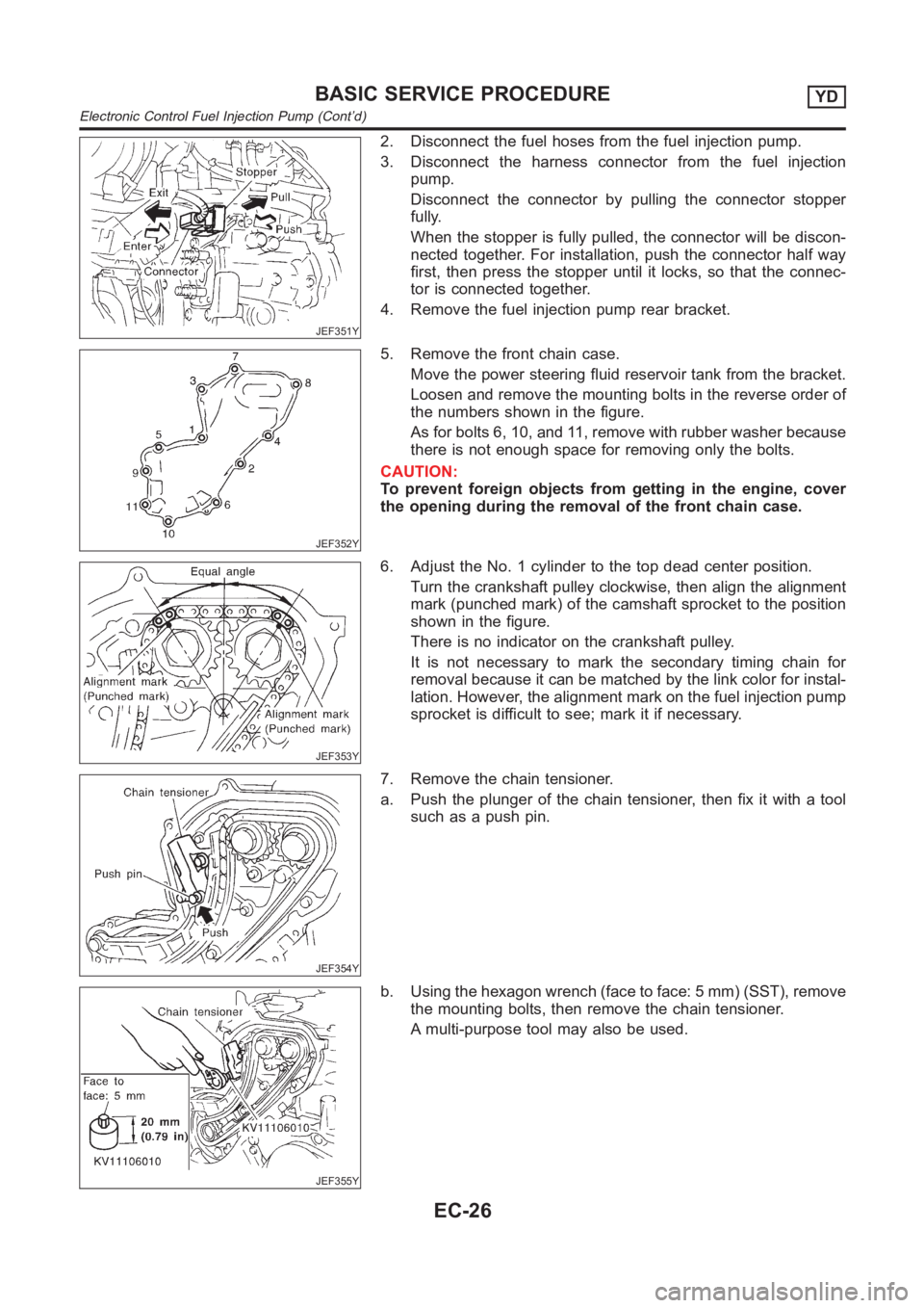
2. Disconnect the fuel hoses from the fuel injection pump.
3. Disconnect the harness connector from the fuel injection
pump.
Disconnect the connector by pulling the connector stopper
fully.
When the stopper is fully pulled, the connector will be discon-
nected together. For installation, push the connector half way
first, then press the stopper until it locks, so that the connec-
tor is connected together.
4. Remove the fuel injection pump rear bracket.
JEF352Y
5. Remove the front chain case.
Move the power steering fluid reservoir tank from the bracket.
Loosen and remove the mounting bolts in the reverse order of
the numbers shown in the figure.
As for bolts 6, 10, and 11, remove with rubber washer because
there is not enough space for removing only the bolts.
CAUTION:
To prevent foreign objects from getting in the engine, cover
the opening during the removal of the front chain case.
JEF353Y
6. Adjust the No. 1 cylinder to the top dead center position.
Turn the crankshaft pulley clockwise, then align the alignment
mark (punched mark) of the camshaft sprocket to the position
shown in the figure.
There is no indicator on the crankshaft pulley.
It is not necessary to mark the secondary timing chain for
removal because it can be matched by the link color for instal-
lation. However, the alignment mark on the fuel injection pump
sprocket is difficult to see; mark it if necessary.
JEF354Y
7. Remove the chain tensioner.
a. Push the plunger of the chain tensioner, then fix it with a tool
such as a push pin.
JEF355Y
b. Using the hexagon wrench (face to face: 5 mm) (SST), remove
the mounting bolts, then remove the chain tensioner.
A multi-purpose tool may also be used.
BASIC SERVICE PROCEDUREYD
Electronic Control Fuel Injection Pump (Cont’d)
EC-26
Page 1081 of 3189

JEF356Y
8. Remove the timing chain slack guide.
Using the hexagon wrench (face to face: 6 mm, short-type)
(SST), remove the mounting bolts, then remove the timing
chain slack guide.
JEF357Y
9. Remove the timing chain tension guide.
10. Remove the secondary timing chain.
Only the timing chain can be removed without removing the
sprockets.
JEF358Y
11. Fix the fuel injection pump sprocket.
a. Insert the positioning stopper pin (SST) in the 6 mm (0.24 in)
dia. hole of the fuel injection pump sprocket.
b. Using the torx wrench (SST), turn the pump shaft gradually to
adjust the hole position of the fuel injection pump sprocket.
c. Insert the positioning stopper pin through the fuel injection
pump body to fix the sprocket.
JEF359Y
Insert the positioning stopper pin until its flange contacts the
fuel injection pump sprocket.
d. Remove the torx wrench (SST).
GI
MA
EM
LC
FE
CL
MT
AT
AX
SU
BR
ST
RS
BT
HA
SC
EL
IDX
BASIC SERVICE PROCEDUREYD
Electronic Control Fuel Injection Pump (Cont’d)
EC-27
Page 1084 of 3189
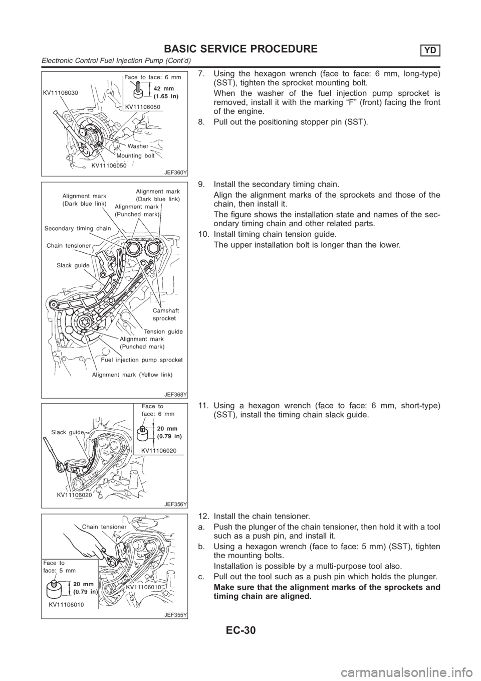
JEF360Y
7. Using the hexagon wrench (face to face: 6 mm, long-type)
(SST), tighten the sprocket mounting bolt.
When the washer of the fuel injection pump sprocket is
removed, install it with the marking “F” (front) facing the front
of the engine.
8. Pull out the positioning stopper pin (SST).
JEF368Y
9. Install the secondary timing chain.
Align the alignment marks of the sprockets and those of the
chain, then install it.
The figure shows the installation state and names of the sec-
ondary timing chain and other related parts.
10. Install timing chain tension guide.
The upper installation bolt is longer than the lower.
JEF356Y
11. Using a hexagon wrench (face to face: 6 mm, short-type)
(SST), install the timing chain slack guide.
JEF355Y
12. Install the chain tensioner.
a. Push the plunger of the chain tensioner, then hold it with a tool
such as a push pin, and install it.
b. Using a hexagon wrench (face to face: 5 mm) (SST), tighten
the mounting bolts.
Installation is possible by a multi-purpose tool also.
c. Pull out the tool such as a push pin which holds the plunger.
Make sure that the alignment marks of the sprockets and
timing chain are aligned.
BASIC SERVICE PROCEDUREYD
Electronic Control Fuel Injection Pump (Cont’d)
EC-30
Page 3183 of 3189
Starting system...............................................SC-13
Steering linkage ..............................................ST-15
Steering switch................................................EL-41
Steering wheel and column ............................ST-10
Steering wheel play ..........................................ST-6
Steering wheel turning force .............................ST-8
Stop lamp switch (QG engine) ......EC-361, EC-630
Stop lamp <0011001100110011001100110011001100110011001100110011001100110011001100110011001100110011001100110011001100110011001100110011001100110011001100110011001100110011001100110011001100110011001100110011001100
110011001100110011[.EL-58
STOP/L - Wiring diagram................................EL-58
Striking rod (M/T) ...............................MT-32, 56, 94
Strut (front) <0011001100110011001100110011001100110011001100110011001100110011001100110011001100110011001100110011001100110011001100110011001100110011001100110011001100110011001100110011001100110011001100110011001100
11[....SU-9
Strut (rear) <0011001100110011001100110011001100110011001100110011001100110011001100110011001100110011001100110011001100110011001100110011001100110011001100110011001100110011001100110011001100110011001100110011001100
110011[..SU-20
Sub-gear (M/T) .........................................MT-31, 55
Sun roof, electric ...........................................EL-249
Sunload sensor...........ATC-106, ATC-108, ATC-118
Sunroof<0011001100110011001100110011001100110011001100110011001100110011001100110011001100110011001100110011001100110011001100110011001100110011001100110011001100110011001100110011001100110011001100110011001100
1100110011001100110011[....BT-60
Super lock <0011001100110011001100110011001100110011001100110011001100110011001100110011001100110011001100110011001100110011001100110011001100110011001100110011001100110011001100110011001100110011001100110011001100
11001100110028[L-301
Supplemental restraint system - Wiring
diagram <0011001100110011001100110011001100110011001100110011001100110011001100110011001100110011001100110011001100110011001100110011001100110011001100110011001100110011001100110011001100110011001100110011001100
1100110011001100110035[S-46
Supplemental Restraint System .....................RS-20
Symbols and abbreviations..............................GI-11
Symptom matrix chart
(QG engine)..................................EC-70, EC-449
Symptom matrix chart (YD engine)................EC-53
Synchronizer (M/T) ............................MT-31, 55, 93
System readiness test (SRT) code
(QG engine) ................................................EC-40
T
Tachometer <0011001100110011001100110011001100110011001100110011001100110011001100110011001100110011001100110011001100110011001100110011001100110011001100110011001100110011001100110011001100110011001100110011001100
1100110028[L-110
Tail lamp <0011001100110011001100110011001100110011001100110011001100110011001100110011001100110011001100110011001100110011001100110011001100110011001100110011001100110011001100110011001100110011001100110011001100
110011001100110011[...EL-55
TCM circuit diagram ........................................AT-15
TCM inspection table .......................AT-107, AT-303
Thermostat................................................LC-15,40
Three way catalyst function
(QG engine) ..............................................EC-247
Three way catalyst precautions.........................GI-6
Throttle body (QG engine) .............................EM-18
Throttle control motor relay
(QG engine)................................EC-286, EC-587
Throttle position sensor (TPS)
(QG engine) ..EC-200, EC-206, EC-336, EC-342,
EC-344, EC-526, EC-532, EC-609,
EC-615, EC-617
Throttle position switch ....................AT-244, AT-340
Throttle valve closed position learning
(QG engine)..................................EC-31, EC-426
Throwout bearing - See Clutch release
bearing ..................................................CL-17,20
Tie-rod ball joints.............................................ST- 1 9
Tie-rod <0011001100110011001100110011001100110011001100110011001100110011001100110011001100110011001100110011001100110011001100110011001100110011001100110011001100110011001100110011001100110011001100110011001100
1100110011001100110011[.....ST-15
Tightening torque of standard bolts.................GI-50
Timing chain (QG engine)..............................EM-47
Timing chain (YD engine) ..............................EM-20
Tire size <0011001100110011001100110011001100110011001100110011001100110011001100110011001100110011001100110011001100110011001100110011001100110011001100110011001100110011001100110011001100110011001100110011001100
110011001100110011[....GI-44
Torque converter installation ............AT-412, AT-509
Tow truck towing ..............................................GI-48
TPS1 - Wiring diagram
(QG engine)................................EC-208, EC-534TPS2 - Wiring diagram
(QG engine) ................................EC-338, EC-611
TPS3 - Wiring diagram
(QG engine)................................EC-202, EC-528
Transmission case (M/T) ...................MT-30, 54, 92
Tread-FR&RR (Dimensions)............................GI-44
Trim <0011001100110011001100110011001100110011001100110011001100110011001100110011001100110011001100110011001100110011001100110011001100110011001100110011001100110011001100110011001100110011001100110011001100
1100110011001100110011001100110011[......BT-31
Trouble diagnoses ...........................................GI-32
Trunk lid finisher..............................................BT- 4 5
Trunk lid opener - See Trunk lid .....................BT-10
Trunk lid trim <0011001100110011001100110011001100110011001100110011001100110011001100110011001100110011001100110011001100110011001100110011001100110011001100110011001100110011001100110011001100110011001100110011001100
11[BT-45
Trunk lid <0011001100110011001100110011001100110011001100110011001100110011001100110011001100110011001100110011001100110011001100110011001100110011001100110011001100110011001100110011001100110011001100110011001100
110011001100110011[...BT-10
Trunk room lamp ...........................................EL-108
Trunk room trim...............................................BT-45
TURN - Wiring diagram ..................................EL-71
Turn signal lamp .............................................EL-67
Two trip detection logic
(QG engine)..................................EC-36, EC-430
Two-pole lift <0011001100110011001100110011001100110011001100110011001100110011001100110011001100110011001100110011001100110011001100110011001100110011001100110011001100110011001100110011001100110011001100110011001100
11[..GI-47
U
Under body <0011001100110011001100110011001100110011001100110011001100110011001100110011001100110011001100110011001100110011001100110011001100110011001100110011001100110011001100110011001100110011001100110011001100
11001100110025[T- 7 7
V
Vacuum hose (brake system).........................BR-22
Vacuum hose drawing (Engine control)
(QG engine)..................................EC-22, EC-417
Vacuum pump.................................................BR-23
Valve clearance (YD engine) .........................EM-59
Valve guide (QG engine) ...............................EM-63
Valve guide (YD engine) ................................EM-50
Valve lifter<0011001100110011001100110011001100110011001100110011001100110011001100110011001100110011001100110011001100110011001100110011001100110011001100110011001100110011001100110011001100110011001100110011001100
110011[...EM-41
Valve seat (QG engine) .................................EM-64
Valve seat (YD engine) ..................................EM-52
Valve spring (QG engine) ..............................EM-66
Valve spring (YD engine) ...............................EM-54
Vehicle speed sensor (VSS)
(QG engine)................................EC-258, EC-679
Vehicle speed sensor (VSS)
(YD engine)...............................................EC-105
Ventilation air filter (manual A/C) ...................HA-95
Ventilation air filter ......................................ATC-129
Viscosity number (SAE) .................................MA-20
Viscous coupling (FF M/T) .............................MT-93
VSS - Wiring diagram (YD engine) ..............EC-105
W
WARN - Wiring diagram ...............................EL-130
Warning chime ..............................................EL-136
Warning lamps ..............................................EL-129
Washer, front .................................................EL-158
Water pump ..............................................LC-14, 38
Water temperature gauge .............................EL-110
Weatherstrip - See Exterior ............................BT-47
GI
MA
EM
LC
EC
FE
CL
MT
AT
AX
SU
BR
ST
RS
BT
HA
SC
EL
ALPHABETICAL INDEX
IDX-9