chain NISSAN ALMERA N16 2003 Electronic Repair Manual
[x] Cancel search | Manufacturer: NISSAN, Model Year: 2003, Model line: ALMERA N16, Model: NISSAN ALMERA N16 2003Pages: 3189, PDF Size: 54.76 MB
Page 6 of 3189
The security indicator is located on the combi meter. The indicator
blinks when the ignition switch is in “OFF” or “ACC” position.
Therefore, NATS warns outsiders that the vehicle is equipped with
the anti-theft system.
When NATS detects trouble, the security indicator lamp lights
up while ignition switch is in “ON” position.
This lighting up indicates that the anti-theft is not functioning,
so prompt service is required.
When servicing NATS (trouble diagnoses, system initialization
and additional registration of other NATS ignition key IDs),
CONSULT-II hardware and CONSULT-II NATS software is
necessary.
Regarding the procedures of NATS initialization and NATS
ignition key ID registration, refer to CONSULT-II operation
manual, NATS.
Therefore, CONSULT-II NATS software (program card and
operation manual) must be kept strictly confidential to main-
tain the integrity of the anti-theft function.
When servicing NATS (trouble diagnoses, system initialization
and additional registration of other NATS ignition key IDs), it
may be necessary to re-register original key identification.
Therefore, be sure to receive all keys from vehicle owner. A
maximum of five key IDs can be registered into NATS.
When failing to start the engine first time using the key of
NATS, start as follows.
a) Leave the ignition key in “ON” position for approximately 5
seconds.
b) Turn ignition key to “OFF” or “LOCK” position and wait approxi-
mately 5 seconds.
c) Repeat step 1 and 2 again.
d) Restart the engine while keeping the key separate from any
others on key-chain.
SGI285
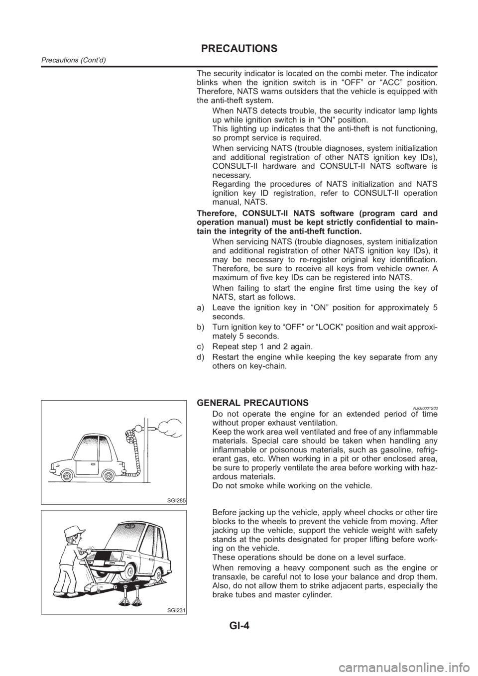
GENERAL PRECAUTIONSNJGI0001S03Do not operate the engine for an extended period of time
without proper exhaust ventilation.
Keep the work area well ventilated and free of any inflammable
materials. Special care should be taken when handling any
inflammable or poisonous materials, such as gasoline, refrig-
erant gas, etc. When working in a pit or other enclosed area,
be sure to properly ventilate the area before working with haz-
ardous materials.
Do not smoke while working on the vehicle.
SGI231
Before jacking up the vehicle, apply wheel chocks or other tire
blocks to the wheels to prevent the vehicle from moving. After
jacking up the vehicle, support the vehicle weight with safety
stands at the points designated for proper lifting before work-
ing on the vehicle.
These operations should be done on a level surface.
When removing a heavy component such as the engine or
transaxle, be careful not to lose your balance and drop them.
Also, do not allow them to strike adjacent parts, especially the
brake tubes and master cylinder.
PRECAUTIONS
Precautions (Cont’d)
GI-4
Page 50 of 3189
SGI805
SGI987
Tow Truck TowingNJGI0009S05CAUTION:
All applicable local laws regarding the towing operation
must be obeyed.
It is necessary to use proper towing equipment to avoid
possible damage to the vehicle during towing operation.
Towing is in accordance with Towing Procedure Manual at
dealer.
Always attach safety chains before towing.
When towing, make sure that the transmission, steering
system and power train are in good order. If any unit is
damaged, dollies must be used.
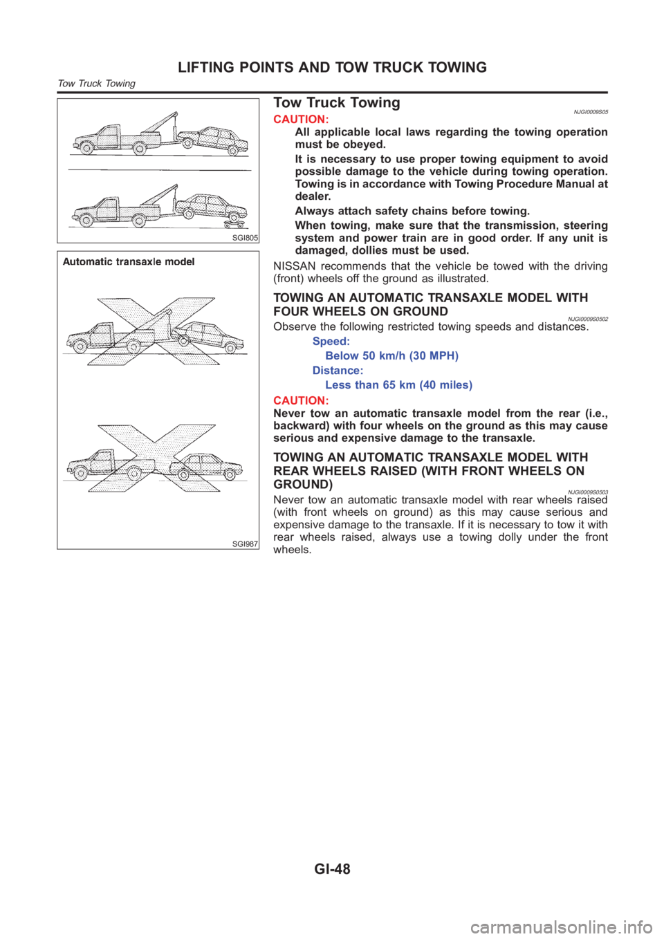
NISSAN recommends that the vehicle be towed with the driving
(front) wheels off the ground as illustrated.
TOWING AN AUTOMATIC TRANSAXLE MODEL WITH
FOUR WHEELS ON GROUND
NJGI0009S0502Observe the following restricted towing speeds and distances.
Speed:
Below 50 km/h (30 MPH)
Distance:
Less than 65 km (40 miles)
CAUTION:
Never tow an automatic transaxle model from the rear (i.e.,
backward) with four wheels on the ground as this may cause
serious and expensive damage to the transaxle.
TOWING AN AUTOMATIC TRANSAXLE MODEL WITH
REAR WHEELS RAISED (WITH FRONT WHEELS ON
GROUND)
NJGI0009S0503Never tow an automatic transaxle model with rear wheels raised
(with front wheels on ground) as this may cause serious and
expensive damage to the transaxle. If it is necessary to tow it with
rear wheels raised, always use a towing dolly under the front
wheels.
LIFTING POINTS AND TOW TRUCK TOWING
Tow Truck Towing
GI-48
Page 88 of 3189
![NISSAN ALMERA N16 2003 Electronic Repair Manual EM-10
[QG]
NOISE, VIBRATION, AND HARSHNESS (NVH) TROUBLESHOOTING
Use the Chart Below to Help You Find the Cause of the Symptom.
EBS00LPX
1. Locate the area where noise occurs.
2. Confirm the type of n](/img/5/57350/w960_57350-87.png "NISSAN ALMERA N16 2003 Electronic Repair Manual EM-10
[QG]
NOISE, VIBRATION, AND HARSHNESS (NVH) TROUBLESHOOTING
Use the Chart Below to Help You Find the Cause of the Symptom.
EBS00LPX
1. Locate the area where noise occurs.
2. Confirm the type of n")
EM-10
[QG]
NOISE, VIBRATION, AND HARSHNESS (NVH) TROUBLESHOOTING
Use the Chart Below to Help You Find the Cause of the Symptom.
EBS00LPX
1. Locate the area where noise occurs.
2. Confirm the type of noise.
3. Specify the operating condition of engine.
4. Check specified noise source.
If necessary, repair or replace these parts.
A: Closely related B: Related C: Sometimes related —: Not relatedLocation
of noiseTy p e o f
noiseOperating condition of engine
Source of
noiseCheck itemRefer-
ence page Before
warm-
upAfter
warm-
upWhen
start-
ingWhen
idlingWhen
racingWhile
driving
Top of
engine
Rocker
cover
Cylinder
headTick in g o r
clickingCA—AB—Tappet
noise
●Valve clearanceEM-42
Rattle C A — A B CCamshaft
bearing
noise
●Camshaft journal
clearance
●Camshaft runoutEM-39EM-39
Crank-
shaft pul-
ley
Cylinder
block
(Side of
engine)
Oil panSlap or
knock—A—B B—Piston pin
noise
●Piston and piston pin
clearance
●Connecting rod
bushing clearanceEM-84EM-87
Slap or
rapA——B B APiston
slap noise
●Piston-to-bore clear-
ance
●Piston ring side
clearance
●Piston ring end gap
●Connecting rod bend
and torsionEM-88
EM-85
EM-86
EM-86
Knock A B C B B BConnect-
ing rod
bearing
noise
●Connecting rod
bushing clearance
(Small end)
●Connecting rod bear-
ing clearance (Big
end)EM-87EM-87
Knock A B — A B CMain
bearing
noise
●Main bearing oil
clearance
●Crankshaft runoutEM-91EM-90
Front of
engine
Timing
chain
coverTapping or
tickingAA—BBBTiming
chain and
chain ten-
sioner
noise●Timing chain cracks
and wear
●Timing chain ten-
sioner operationEM-51EM-47
Front of
engineSqueak-
ing or fizz-
ingAB—B—CDrive belts
(Sticking
or slip-
ping)
●Drive belts deflection
EM-11
CreakingABABABDrive belts
(Slipping)●Idler pulley bearing
operation
Squall
CreakAB—BABWater
pump
noise
●Water pump opera-
tionLC-14
Page 110 of 3189
![NISSAN ALMERA N16 2003 Electronic Repair Manual EM-32
[QG]
CAMSHAFT
CAMSHAFT
PFP:13001
Removal and InstallationEBS00LQB
CAUTION:
Prior to installation, apply engine oil to the parts marked in the figure.
REMOVAL
1. Remove rocker cover. Refer to EM-](/img/5/57350/w960_57350-109.png "NISSAN ALMERA N16 2003 Electronic Repair Manual EM-32
[QG]
CAMSHAFT
CAMSHAFT
PFP:13001
Removal and InstallationEBS00LQB
CAUTION:
Prior to installation, apply engine oil to the parts marked in the figure.
REMOVAL
1. Remove rocker cover. Refer to EM-")
EM-32
[QG]
CAMSHAFT
CAMSHAFT
PFP:13001
Removal and InstallationEBS00LQB
CAUTION:
Prior to installation, apply engine oil to the parts marked in the figure.
REMOVAL
1. Remove rocker cover. Refer to EM-29, "ROCKER COVER" .
2. Remove cylinder head front cover.
●Move harness secured to front surface beforehand.
3. Set No. 1 cylinder at TDC of its compression stroke.
a. Remove RH splash cover (integrated with undercover).
b. Rotate crankshaft pulley clockwise and align yellow paint mark
with timing indicator.
PBIC0965E
1. Camshaft bracket 2. Camshaft sprocket (INT) 3. Camshaft sprocket (EXH)
4. Washer 5. Cylinder head front cover 6. Chain tensioner
7. Valve lifter 8. Adjusting shim (If so equipped) 9. Camshaft (EXH)
10. Camshaft (INT)
MBIB0193E
Page 111 of 3189
![NISSAN ALMERA N16 2003 Electronic Repair Manual CAMSHAFT
EM-33
[QG]
C
D
E
F
G
H
I
J
K
L
MA
EM
c. Confirm mating marks stamped on intake and exhaust sprockets
are located as shown.
●If not, rotate crankshaft pulley as shown and align them.
d. Refe](/img/5/57350/w960_57350-110.png "NISSAN ALMERA N16 2003 Electronic Repair Manual CAMSHAFT
EM-33
[QG]
C
D
E
F
G
H
I
J
K
L
MA
EM
c. Confirm mating marks stamped on intake and exhaust sprockets
are located as shown.
●If not, rotate crankshaft pulley as shown and align them.
d. Refe")
CAMSHAFT
EM-33
[QG]
C
D
E
F
G
H
I
J
K
L
MA
EM
c. Confirm mating marks stamped on intake and exhaust sprockets
are located as shown.
●If not, rotate crankshaft pulley as shown and align them.
d. Referring to mating marks on intake and exhaust camshaft
sprockets, put paint mating marks on timing chain links.
4. Set intake camshaft sprocket to most advanced position.
CAUTION:
Removal/installation of intake camshaft sprocket is required to maintain most advanced position
because of following reasons. Therefore, follow procedure exactly.
●Sprocket and vane (camshaft in front) rotate and become
offset within specific angle range.
●When engine is stationary, vane is located at most
retarded position. Vane is fixed to sprocket by internal
lock pin. Therefore, it does not rotate.
●If camshaft sprocket mounting bolts are turned under
above circumstance, lock pin will be damaged by lateral
load (shear stress). It may cause non-standard operation.
●Set intake camshaft sprocket to most advanced position as
follows.
NOTE:
“Rotating direction” means direction viewed from engine front side.
CAUTION:
Do not remove chain tensioner before performing this step.
a. Using a wrench, hold hexagonal part so that intake camshaft
does not move.
b. Using an air gun, apply air pressure to intake valve timing con-
trol solenoid valve advanced side oil passage on top surface of
No. 1 camshaft bracket.
●Keep applying air pressure until step “d” is completed.
CAUTION:
●Be careful not to damage oil passage from interference of
air gun tip.
●Thoroughly wipe off oil before applying air pressure.
When applying air pressure, cover around air gun using a rag. Wear protective glasses if neces-
sary.
MBIB0194E
MBIB0195E
MBIB0196E
Compression pressure
: 300 kPa (3.00 bar, 3.06 kg/cm
2 , 43.5 psi) or more
MBIB0197E
Page 112 of 3189
![NISSAN ALMERA N16 2003 Electronic Repair Manual EM-34
[QG]
CAMSHAFT
c. Slowly turn intake camshaft in direction A (counterclockwise:
intake manifold side).
●Perform while applying air pressure.
CAUTION:
Be careful not to dislocate camshaft retain](/img/5/57350/w960_57350-111.png "NISSAN ALMERA N16 2003 Electronic Repair Manual EM-34
[QG]
CAMSHAFT
c. Slowly turn intake camshaft in direction A (counterclockwise:
intake manifold side).
●Perform while applying air pressure.
CAUTION:
Be careful not to dislocate camshaft retain")
EM-34
[QG]
CAMSHAFT
c. Slowly turn intake camshaft in direction A (counterclockwise:
intake manifold side).
●Perform while applying air pressure.
CAUTION:
Be careful not to dislocate camshaft retaining spanner.
d. During above step, operating click (a sound indicating internal
lock pin is disengaged) is heard from inside of intake camshaft
sprocket. After hearing it, slowly turn intake camshaft in direction
B (clockwise: exhaust manifold side), and set to most advanced
position.
●Perform while applying air pressure.
●When vane rotates solely against sprocket, lock pin is disengaged even if operating click is not heard.
●If lock pin is not disengaged, apply vibration by jiggling the camshaft with a spanner.
●If lock pin is not disengaged with above step, hit intake camshaft in front by using plastic hammer.
e. The following status indicates that most advanced position is
achieved: vane starts rotating on its own, then sprocket also
starts rotating when camshaft is turned. When above status is
achieved, this step is complete.
●Most advanced position is confirmed when stopper pin groove
and lock pin breathing groove are aligned.
f. Stop air, insert stopper pin [approximately 3 mm (0.12 in) dia.,
length of inserted part is approximately 15 mm (0.59 in)] into
pinhole on camshaft sprocket to fix most advanced position.
NOTE:
In the figure, an Allen wrench [a/f 2.5 mm (0.091 in), short part:
approximately 20 mm (0.79 in), long part: approximately 50 mm
(1.97 in)] is used for stopper pin as an example.
CAUTION:
Load (spring reaction force) is not applied to stopper pin.
Pin is easily detached. Therefore, secure it with vinyl tape to
prevent detachment.
5. Remove chain tensioner.
●Remove in the following order.
a. Press plate down, and release stopper tab.
b. Insert plunger into tensioner body until it stops.
c. Secure plate by passing stopper pin (such as a hard wire)
through plate hole and body hole. (Plunger is also secured.)
d. Remove mounting bolts, and remove chain tensioner.
KBIA1414J
MBIB0198E
PBIC0966E
MBIB0201E
Page 113 of 3189
![NISSAN ALMERA N16 2003 Electronic Repair Manual CAMSHAFT
EM-35
[QG]
C
D
E
F
G
H
I
J
K
L
MA
EM
6. While holding hexagonal part of camshaft with a spanner, loosen
mounting bolts and remove intake and exhaust camshaft
sprockets.
CAUTION:
●Be careful](/img/5/57350/w960_57350-112.png "NISSAN ALMERA N16 2003 Electronic Repair Manual CAMSHAFT
EM-35
[QG]
C
D
E
F
G
H
I
J
K
L
MA
EM
6. While holding hexagonal part of camshaft with a spanner, loosen
mounting bolts and remove intake and exhaust camshaft
sprockets.
CAUTION:
●Be careful")
CAMSHAFT
EM-35
[QG]
C
D
E
F
G
H
I
J
K
L
MA
EM
6. While holding hexagonal part of camshaft with a spanner, loosen
mounting bolts and remove intake and exhaust camshaft
sprockets.
CAUTION:
●Be careful that tool does not interfere with A/C piping.
●Avoid securing camshaft at other than hexagonal part
and loosening mounting bolts by utilizing tension of tim-
ing chain.
●Handle intake camshaft sprocket, taking care of following.
CAUTION:
●Secure stopper pin with vinyl tape to prevent detach-
ment.
●Avoid dropping it or subjecting it to impact.
●Do not disassemble. (Do not loosen 3 bolts on front sur-
face.)
NOTE:
If stopper pin is detached and lock pin is engaged at most retarded position during removal, recover as
follows.
a. Reinstall stopper pin to intake camshaft, and tighten intake camshaft sprocket mounting bolts so that air
does not leak.
CAUTION:
Tightening torque for mounting bolts must be minimum so that air does not leak, preventing dam-
age on internal lock pin.
b. Apply air pressure to disengage lock pin, and turn vane to most advanced position. (This step can be per-
formed with timing chain removed.)
c. Reinstall stopper pin.
d. Remove intakecamshaft sprocket from camshaft.
7. Remove camshaft brackets.
●Loosen mounting bolts in several steps in reverse order
shown in figure.
8. Remove camshaft.
CAUTION:
Be careful not to damage signal plate on rear end of intake
camshaft and crankshaft.
9. Remove adjusting shims and valve lifters.
●Identify installation position of each valve. Arrange removed
valves so they cannot be mixed up.
INSTALLATION
1. Install valve lifters and adjusting shims.
●Install them in their original positions.
●Install adjusting shim with its stamped mark facing downward (valve lifter side).
EMD0826D
MBIB0202E
PBIC0969E
Page 115 of 3189
![NISSAN ALMERA N16 2003 Electronic Repair Manual CAMSHAFT
EM-37
[QG]
C
D
E
F
G
H
I
J
K
L
MA
EM
CAUTION:
Stopper pin is easily detached. Secure it with vinyl tape to prevent detachment.
a. Install timing chain by aligning its mating mark (mar](/img/5/57350/w960_57350-114.png "NISSAN ALMERA N16 2003 Electronic Repair Manual CAMSHAFT
EM-37
[QG]
C
D
E
F
G
H
I
J
K
L
MA
EM
CAUTION:
Stopper pin is easily detached. Secure it with vinyl tape to prevent detachment.
a. Install timing chain by aligning its mating mark (mar")
CAMSHAFT
EM-37
[QG]
C
D
E
F
G
H
I
J
K
L
MA
EM
CAUTION:
Stopper pin is easily detached. Secure it with vinyl tape to prevent detachment.
a. Install timing chain by aligning its mating mark (marked when
timing chain is removed) with mark on camshaft sprocket.
●Align dowel pin on camshaft front surface and pinhole on
sprocket backside, then install.
b. While holding hexagonal part of camshaft with a spanner,
tighten intake camshaft sprocket mounting bolts.
●Make sure that stopper pin is not detached.
6. Install exhaust camshaft sprocket as follows.
a. Install timing chain by aligning its mating mark (marked when
timing chain is removed) with mark on camshaft sprocket.
●Align dowel pin on camshaft front surface and pinhole on
sprocket, then install.
b. While holding hexagonal part of camshaft with a spanner,
tighten exhaust camshaft sprocket mounting bolts.
NOTE:
Tightening torque is different from intake side tightening torque.
c. Make sure that mating marks on intake/exhaust camshaft
sprockets and mating mark on timing chain are aligned.
7. Install chain tensioner.
●Hold plate and plunger with a stopper pin, then install them.
●After installation, remove stopper pin and release plunger.
●Make sure again that mating marks on intake/exhaust cam-
shaft sprockets and mating mark on timing chain are aligned.
MBIB0208E
MBIB0209E
MBIB0210E
MBIB0211E
Page 125 of 3189
![NISSAN ALMERA N16 2003 Electronic Repair Manual TIMING CHAIN
EM-47
[QG]
C
D
E
F
G
H
I
J
K
L
MA
EM
TIMING CHAINPFP:13028
Removal and InstallationEBS00LQD
CAUTION:
Apply new engine oil to parts marked in illustration before installation.
REMOVAL
1. P](/img/5/57350/w960_57350-124.png "NISSAN ALMERA N16 2003 Electronic Repair Manual TIMING CHAIN
EM-47
[QG]
C
D
E
F
G
H
I
J
K
L
MA
EM
TIMING CHAINPFP:13028
Removal and InstallationEBS00LQD
CAUTION:
Apply new engine oil to parts marked in illustration before installation.
REMOVAL
1. P")
TIMING CHAIN
EM-47
[QG]
C
D
E
F
G
H
I
J
K
L
MA
EM
TIMING CHAINPFP:13028
Removal and InstallationEBS00LQD
CAUTION:
Apply new engine oil to parts marked in illustration before installation.
REMOVAL
1. Place vehicle on lift.
PBIC0971E
1. Cylinder head front cover 2. Camshaft sprocket (INT) 3. Washer
4. Camshaft sprocket (EXH) 5. Chain tensioner 6. Chain slack guide
7. O-ring 8. Power steering pump adjusting bar 9. Crankshaft pulley
10. Front oil seal 11. Front cover 12. Chain tension guide
13. Dowel pin 14. Timing chain 15. Oil pump drive spacer
16. Crankshaft sprocket 17. O-ring (with collar) 18. Auxiliary bolt of cylinder head
Page 126 of 3189
![NISSAN ALMERA N16 2003 Electronic Repair Manual EM-48
[QG]
TIMING CHAIN
2. Disconnect battery ground cable.
3. Remove undercover, front RH wheel and RH splash cover.
4. Drain engine coolant from radiator and cylinder block. Refer to LC-17, "Cha](/img/5/57350/w960_57350-125.png "NISSAN ALMERA N16 2003 Electronic Repair Manual EM-48
[QG]
TIMING CHAIN
2. Disconnect battery ground cable.
3. Remove undercover, front RH wheel and RH splash cover.
4. Drain engine coolant from radiator and cylinder block. Refer to LC-17, \"Cha")
EM-48
[QG]
TIMING CHAIN
2. Disconnect battery ground cable.
3. Remove undercover, front RH wheel and RH splash cover.
4. Drain engine coolant from radiator and cylinder block. Refer to LC-17, "Changing Engine Coolant".
5. Drain engine oil from oil pan.
6. Remove drive belt. Refer to EM-13, "
Removal and Installation" .
7. Remove power steering pump from adjusting bar.
8. Remove alternator. SC-33, "Removal and Installation".
9. Remove ignition coils. Refer to EM-24, "
IGNITION COIL" .
10. Remove rocker cover. Refer to EM-29, "
Removal and Installation" .
11. Remove oil level gauge.
12. Remove exhaust front tube. Refer to FE-10, "Removal and Installation".
13. Remove center member.
14. Remove gusset.
15. Remove rear plate (lower) (A/T models).
16. Remove oil pan and oil strainer. Refer to EM-22, "
Removal and Installation" .
17. For safe operation, and to reduce load to mount insulator, install removed center member again.
18. Remove engine front-side (right side of vehicle) engine mount. Refer to EM-67, "
ENGINE ASSEMBLY" .
a. Remove any parts that cause difficulties for operation around mount, or perform transfer.
b. Support cylinder block bottom surface with a transmission jack.
CAUTION:
●When applying jack, use a wooden block to avoid damage to oil pan mounting surface.
●While performing following operations, support engine front-side with jack.
c. Separate engine mounting insulator and bracket.
d. Remove engine mounting bracket.
19. Remove cylinder head front cover.
●Move harness which was previously fixed on front surface.
20. Remove auxiliary bolts of cylinder head.
21. Set the No. 1 cylinder to the compression TDC.
a. Turn the crankshaft pulley clockwise, and align the timing indica-
tor of the gear case to the timing mark of the crankshaft pulley.
PBIC0557E
PBIC0750E