p1251 NISSAN ALMERA N16 2003 Electronic Repair Manual
[x] Cancel search | Manufacturer: NISSAN, Model Year: 2003, Model line: ALMERA N16, Model: NISSAN ALMERA N16 2003Pages: 3189, PDF Size: 54.76 MB
Page 1056 of 3189
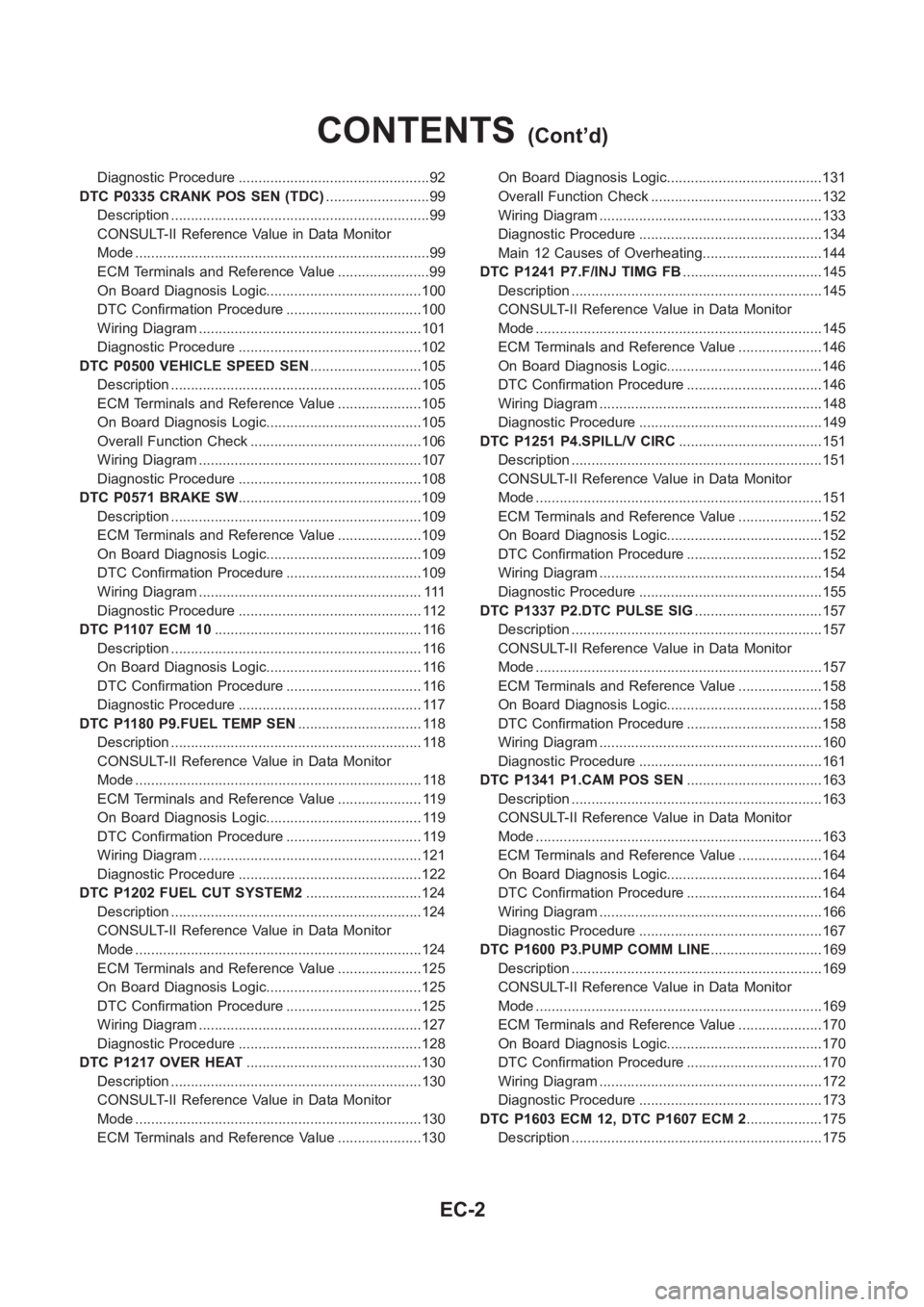
Diagnostic Procedure ................................................92
DTC P0335 CRANK POS SEN (TDC)..........................99
Description <0011001100110011001100110011001100110011001100110011001100110011001100110011001100110011001100110011001100110011001100110011001100110011001100110011001100110011001100110011001100110011001100110011001100
110011[.............99
CONSULT-II Reference Value in Data Monitor
Mode <0011001100110011001100110011001100110011001100110011001100110011001100110011001100110011001100110011001100110011001100110011001100110011001100110011001100110011001100110011001100110011001100110011001100
1100110011001100110011001100110011[...............99
ECM Terminals and Reference Value .......................99
On Board Diagnosis Logic.......................................100
DTC Confirmation Procedure ..................................100
Wiring Diagram ........................................................101
Diagnostic Procedure ..............................................102
DTC P0500 VEHICLE SPEED SEN............................105
Description <0011001100110011001100110011001100110011001100110011001100110011001100110011001100110011001100110011001100110011001100110011001100110011001100110011001100110011001100110011001100110011001100110011001100
110011[...........105
ECM Terminals and Reference Value .....................105
On Board Diagnosis Logic.......................................105
Overall Function Check ...........................................106
Wiring Diagram ........................................................107
Diagnostic Procedure ..............................................108
DTC P0571 BRAKE SW..............................................109
Description <0011001100110011001100110011001100110011001100110011001100110011001100110011001100110011001100110011001100110011001100110011001100110011001100110011001100110011001100110011001100110011001100110011001100
110011[...........109
ECM Terminals and Reference Value .....................109
On Board Diagnosis Logic.......................................109
DTC Confirmation Procedure ..................................109
Wiring Diagram ........................................................ 111
Diagnostic Procedure .............................................. 112
DTC P1107 ECM 10<0011001100110011001100110011001100110011001100110011001100110011001100110011001100110011001100110011001100110011001100110011001100110011001100110011001100110011001100110011001100110011001100110011001100
110011[ 116
Description <0011001100110011001100110011001100110011001100110011001100110011001100110011001100110011001100110011001100110011001100110011001100110011001100110011001100110011001100110011001100110011001100110011001100
110011[........... 116
On Board Diagnosis Logic....................................... 116
DTC Confirmation Procedure .................................. 116
Diagnostic Procedure .............................................. 117
DTC P1180 P9.FUEL TEMP SEN............................... 118
Description <0011001100110011001100110011001100110011001100110011001100110011001100110011001100110011001100110011001100110011001100110011001100110011001100110011001100110011001100110011001100110011001100110011001100
110011[........... 118
CONSULT-II Reference Value in Data Monitor
Mode <0011001100110011001100110011001100110011001100110011001100110011001100110011001100110011001100110011001100110011001100110011001100110011001100110011001100110011001100110011001100110011001100110011001100
1100110011001100110011001100110011[............. 118
ECM Terminals and Reference Value ..................... 119
On Board Diagnosis Logic....................................... 119
DTC Confirmation Procedure .................................. 119
Wiring Diagram ........................................................121
Diagnostic Procedure ..............................................122
DTC P1202 FUEL CUT SYSTEM2.............................124
Description <0011001100110011001100110011001100110011001100110011001100110011001100110011001100110011001100110011001100110011001100110011001100110011001100110011001100110011001100110011001100110011001100110011001100
110011[...........124
CONSULT-II Reference Value in Data Monitor
Mode <0011001100110011001100110011001100110011001100110011001100110011001100110011001100110011001100110011001100110011001100110011001100110011001100110011001100110011001100110011001100110011001100110011001100
1100110011001100110011001100110011[.............124
ECM Terminals and Reference Value .....................125
On Board Diagnosis Logic.......................................125
DTC Confirmation Procedure ..................................125
Wiring Diagram ........................................................127
Diagnostic Procedure ..............................................128
DTC P1217 OVER HEAT............................................130
Description <0011001100110011001100110011001100110011001100110011001100110011001100110011001100110011001100110011001100110011001100110011001100110011001100110011001100110011001100110011001100110011001100110011001100
110011[...........130
CONSULT-II Reference Value in Data Monitor
Mode <0011001100110011001100110011001100110011001100110011001100110011001100110011001100110011001100110011001100110011001100110011001100110011001100110011001100110011001100110011001100110011001100110011001100
1100110011001100110011001100110011[.............130
ECM Terminals and Reference Value .....................130On Board Diagnosis Logic.......................................131
Overall Function Check ...........................................132
Wiring Diagram ........................................................133
Diagnostic Procedure ..............................................134
Main 12 Causes of Overheating..............................144
DTC P1241 P7.F/INJ TIMG FB...................................145
Description <0011001100110011001100110011001100110011001100110011001100110011001100110011001100110011001100110011001100110011001100110011001100110011001100110011001100110011001100110011001100110011001100110011001100
110011[...........145
CONSULT-II Reference Value in Data Monitor
Mode <0011001100110011001100110011001100110011001100110011001100110011001100110011001100110011001100110011001100110011001100110011001100110011001100110011001100110011001100110011001100110011001100110011001100
1100110011001100110011001100110011[.............145
ECM Terminals and Reference Value .....................146
On Board Diagnosis Logic.......................................146
DTC Confirmation Procedure ..................................146
Wiring Diagram ........................................................148
Diagnostic Procedure ..............................................149
DTC P1251 P4.SPILL/V CIRC....................................151
Description <0011001100110011001100110011001100110011001100110011001100110011001100110011001100110011001100110011001100110011001100110011001100110011001100110011001100110011001100110011001100110011001100110011001100
110011[
...........151
CONSULT-II Reference Value in Data Monitor
Mode <0011001100110011001100110011001100110011001100110011001100110011001100110011001100110011001100110011001100110011001100110011001100110011001100110011001100110011001100110011001100110011001100110011001100
1100110011001100110011001100110011[.............151
ECM Terminals and Reference Value .....................152
On Board Diagnosis Logic.......................................152
DTC Confirmation Procedure ..................................152
Wiring Diagram ........................................................154
Diagnostic Procedure ..............................................155
DTC P1337 P2.DTC PULSE SIG................................157
Description <0011001100110011001100110011001100110011001100110011001100110011001100110011001100110011001100110011001100110011001100110011001100110011001100110011001100110011001100110011001100110011001100110011001100
110011[...........157
CONSULT-II Reference Value in Data Monitor
Mode <0011001100110011001100110011001100110011001100110011001100110011001100110011001100110011001100110011001100110011001100110011001100110011001100110011001100110011001100110011001100110011001100110011001100
1100110011001100110011001100110011[.............157
ECM Terminals and Reference Value .....................158
On Board Diagnosis Logic.......................................158
DTC Confirmation Procedure ..................................158
Wiring Diagram ........................................................160
Diagnostic Procedure ..............................................161
DTC P1341 P1.CAM POS SEN..................................163
Description <0011001100110011001100110011001100110011001100110011001100110011001100110011001100110011001100110011001100110011001100110011001100110011001100110011001100110011001100110011001100110011001100110011001100
110011[...........163
CONSULT-II Reference Value in Data Monitor
Mode <0011001100110011001100110011001100110011001100110011001100110011001100110011001100110011001100110011001100110011001100110011001100110011001100110011001100110011001100110011001100110011001100110011001100
1100110011001100110011001100110011[.............163
ECM Terminals and Reference Value .....................164
On Board Diagnosis Logic.......................................164
DTC Confirmation Procedure ..................................164
Wiring Diagram ........................................................166
Diagnostic Procedure ..............................................167
DTC P1600 P3.PUMP COMM LINE............................169
Description <0011001100110011001100110011001100110011001100110011001100110011001100110011001100110011001100110011001100110011001100110011001100110011001100110011001100110011001100110011001100110011001100110011001100
110011[...........169
CONSULT-II Reference Value in Data Monitor
Mode <0011001100110011001100110011001100110011001100110011001100110011001100110011001100110011001100110011001100110011001100110011001100110011001100110011001100110011001100110011001100110011001100110011001100
1100110011001100110011001100110011[.............169
ECM Terminals and Reference Value .....................170
On Board Diagnosis Logic.......................................170
DTC Confirmation Procedure ..................................170
Wiring Diagram ........................................................172
Diagnostic Procedure ..............................................173
DTC P1603 ECM 12, DTC P1607 ECM 2...................175
Description <0011001100110011001100110011001100110011001100110011001100110011001100110011001100110011001100110011001100110011001100110011001100110011001100110011001100110011001100110011001100110011001100110011001100
110011[...........175
CONTENTS(Cont’d)
EC-2
Page 1058 of 3189
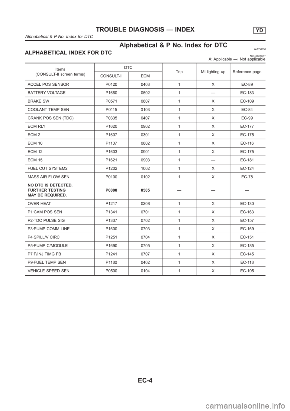
Alphabetical & P No. Index for DTCNJEC0600ALPHABETICAL INDEX FOR DTCNJEC0600S01X: Applicable —: Not applicable
Items
(CONSULT-II screen terms)DTC
Trip MI lighting up Reference page
CONSULT-II ECM
ACCEL POS SENSOR P0120 0403 1 X EC-89
BATTERY VOLTAGE P1660 0502 1 — EC-183
BRAKE SW P0571 0807 1 X EC-109
COOLANT TEMP SEN P0115 0103 1 X EC-84
CRANK POS SEN (TDC) P0335 0407 1 X EC-99
ECM RLY P1620 0902 1 X EC-177
ECM 2 P1607 0301 1 X EC-175
ECM 10 P1107 0802 1 X EC-116
ECM 12 P1603 0901 1 X EC-175
ECM 15 P1621 0903 1 — EC-181
FUEL CUT SYSTEM2 P1202 1002 1 X EC-124
MASS AIR FLOW SEN P0100 0102 1 X EC-78
NO DTC IS DETECTED.
FURTHER TESTING
MAY BE REQUIRED.P0000 0505———
OVER HEAT P1217 0208 1 X EC-130
P1·CAM POS SEN P1341 0701 1 X EC-163
P2·TDC PULSE SIG P1337 0702 1 X EC-157
P3·PUMP COMM LINE P1600 0703 1 X EC-169
P4·SPILL/V CIRC P1251 0704 1 X EC-151
P5·PUMP C/MODULE P1690 0705 1 X EC-185
P7·F/INJ TIMG FB P1241 0707 1 X EC-145
P9·FUEL TEMP SEN P1180 0402 1 X EC-118
VEHICLE SPEED SEN P0500 0104 1 X EC-105
TROUBLE DIAGNOSIS — INDEXYD
Alphabetical & P No. Index for DTC
EC-4
Page 1059 of 3189
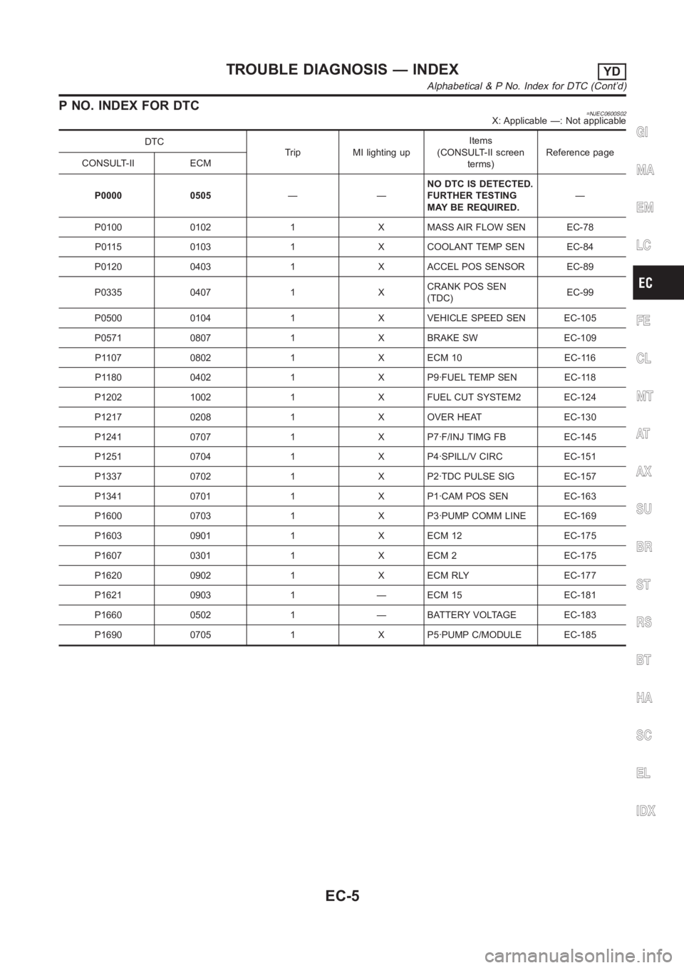
P NO. INDEX FOR DTC=NJEC0600S02X: Applicable —: Not applicable
DTC
Trip MI lighting upItems
(CONSULT-II screen
terms)Reference page
CONSULT-II ECM
P0000 0505——NO DTC IS DETECTED.
FURTHER TESTING
MAY BE REQUIRED.—
P0100 0102 1 X MASS AIR FLOW SEN EC-78
P0115 0103 1 X COOLANT TEMP SEN EC-84
P0120 0403 1 X ACCEL POS SENSOR EC-89
P0335 0407 1 XCRANK POS SEN
(TDC)EC-99
P0500 0104 1 X VEHICLE SPEED SEN EC-105
P0571 0807 1 X BRAKE SW EC-109
P1107 0802 1 X ECM 10 EC-116
P1180 0402 1 X P9·FUEL TEMP SEN EC-118
P1202 1002 1 X FUEL CUT SYSTEM2 EC-124
P1217 0208 1 X OVER HEAT EC-130
P1241 0707 1 X P7·F/INJ TIMG FB EC-145
P1251 0704 1 X P4·SPILL/V CIRC EC-151
P1337 0702 1 X P2·TDC PULSE SIG EC-157
P1341 0701 1 X P1·CAM POS SEN EC-163
P1600 0703 1 X P3·PUMP COMM LINE EC-169
P1603 0901 1 X ECM 12 EC-175
P1607 0301 1 X ECM 2 EC-175
P1620 0902 1 X ECM RLY EC-177
P1621 0903 1 — ECM 15 EC-181
P1660 0502 1 — BATTERY VOLTAGE EC-183
P1690 0705 1 X P5·PUMP C/MODULE EC-185GI
MA
EM
LC
FE
CL
MT
AT
AX
SU
BR
ST
RS
BT
HA
SC
EL
IDX
TROUBLE DIAGNOSIS — INDEXYD
Alphabetical & P No. Index for DTC (Cont’d)
EC-5
Page 1205 of 3189

SEF437Y
DescriptionNJEC0714SYSTEM DESCRIPTIONNJEC0714S01The ECM and the electronic control fuel injection pump control unit
(abbreviated as the injection pump control unit) perform the real
time communication (signal exchange).
The ECM transmits the signals of the target fuel injection amount,
target fuel injection timing, and engine speed, etc., and receives
the signals of the pump speed and fuel temperature, etc. from the
injection pump control unit.
By those signals, the injection pump controls the optimum fuel
injection amount and injection timing of the spill valve and timing
control valve.
Injection pump control unit has an on board diagnostic system,
which detects malfunctions related to sensors or actuators built-into
electronic control fuel injection pump. These malfunction informa-
tion are transferred through the line (circuit) from injection pump
control unit to ECM.
FUEL INJECTION AMOUNT CONTROLNJEC0714S02In accordance with the target fuel injection amount signal from the
ECM, the injection amount is controlled by controlling the spill valve
in the injection pump and by changing the needle opening time.
FUEL INJECTION TIMING CONTROLNJEC0714S03Based on the target fuel injection timing signal from the ECM, the
injection timing is controlled in accordance with the timer spring by
performing the duty control of the timing control valve in the injec-
tion pump and by adjusting the pressure of the timer piston high
pressure chamber.
FUEL TEMPERATURE SENSORNJEC0714S04The sensor detects the fuel temperature in the injection pump and
calibrates the injection amount change by the fuel temperature.
CAM RING POSITION SENSORNJEC0714S05The sensor detects the passing of the protrusion on the sensor
wheel in the injection pump by the semiconductor magnetic resis-
tance element sensor. The cam ring position sensor synchronizes
with the cam ring, and detects the actual advance amount. The
injection pump control unit measures the injection pump revolution
by the signal of the cam ring position sensor.
CONSULT-II Reference Value in Data Monitor
Mode
NJEC0715Remarks: Specification data are reference values.
MONITOR ITEM CONDITION SPECIFICATION
FUEL TEMP SEN Engine: After warming up More than 40°C (104°F)
SPILL/V Engine: After warming up, idle the engine. Approx. 12 - 13°CA
INT/A VOLUME Engine: After warming up, idle the engine. Approx. 150 - 450 mg/st
F/CUT SIGNAL Engine: After warming up Idle ON
GI
MA
EM
LC
FE
CL
MT
AT
AX
SU
BR
ST
RS
BT
HA
SC
EL
IDX
DTC P1251 P4·SPILL/V CIRCYD
Description
EC-151
Page 1206 of 3189
MONITOR ITEM CONDITION SPECIFICATION
BARO SEN Ignition switch: ONAltitude
Approx. 0 m (0 ft): Approx. 100.62
kPa (1.0062 bar, 1.026 kg/cm
2,
14.59 psi)
Approx. 1,000 m (3,281 ft): Approx.
88.95 kPa (0.8895 bar, 0.907
kg/cm
2, 12.90 psi)
Approx. 1,500 m (4,922 ft): Approx.
83.16 kPa (0.8316 bar, 0.848
kg/cm
2, 12.06 psi)
Approx. 2,000 m (6,562 ft): Approx.
78.36 kPa (0.7836 bar, 0.799
kg/cm
2, 11.36 psi)
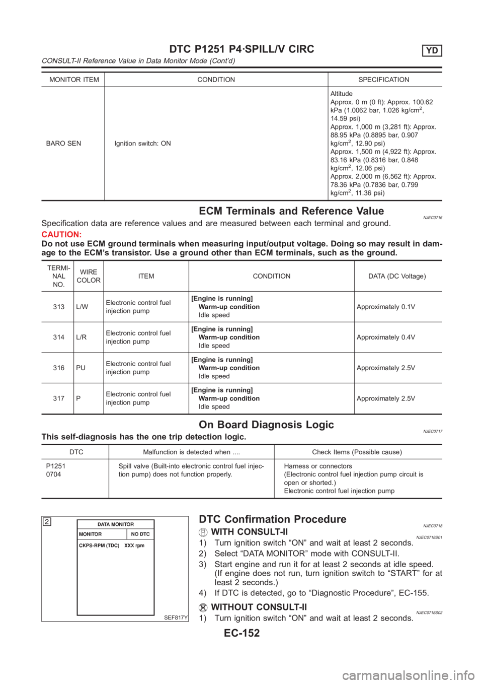
ECM Terminals and Reference ValueNJEC0716Specification data are reference values and are measured between each terminal and ground.
CAUTION:
Do not use ECM ground terminals when measuring input/output voltage. Doing so may result in dam-
age to the ECM’s transistor. Use a ground other than ECM terminals, such as the ground.
TERMI-
NAL
NO.WIRE
COLORITEM CONDITION DATA (DC Voltage)
313 L/WElectronic control fuel
injection pump[Engine is running]
Warm-up condition
Idle speedApproximately 0.1V
314 L/RElectronic control fuel
injection pump[Engine is running]
Warm-up condition
Idle speedApproximately 0.4V
316 PUElectronic control fuel
injection pump[Engine is running]
Warm-up condition
Idle speedApproximately 2.5V
317 PElectronic control fuel
injection pump[Engine is running]
Warm-up condition
Idle speedApproximately 2.5V
On Board Diagnosis LogicNJEC0717This self-diagnosis has the one trip detection logic.
DTC Malfunction is detected when .... Check Items (Possible cause)
P1251
0704Spill valve (Built-into electronic control fuel injec-
tion pump) does not function properly.Harness or connectors
(Electronic control fuel injection pump circuit is
open or shorted.)
Electronic control fuel injection pump
SEF817Y
DTC Confirmation ProcedureNJEC0718WITH CONSULT-IINJEC0718S011) Turn ignition switch “ON” and wait at least 2 seconds.
2) Select “DATA MONITOR” mode with CONSULT-II.
3) Start engine and run it for at least 2 seconds at idle speed.
(If engine does not run, turn ignition switch to “START” for at
least 2 seconds.)
4) If DTC is detected, go to “Diagnostic Procedure”, EC-155.
WITHOUT CONSULT-IINJEC0718S021) Turn ignition switch “ON” and wait at least 2 seconds.
DTC P1251 P4·SPILL/V CIRCYD
CONSULT-II Reference Value in Data Monitor Mode (Cont’d)
EC-152
Page 1207 of 3189
2) Start engine and run it for at least 2 seconds at idle speed.
(If engine does not run, turn ignition switch to “START” for at
least 2 seconds.)
3) Turn ignition switch “OFF”, wait at least 5 seconds and then
turn “ON”.
4) Perform “Diagnostic Test Mode II (Self-diagnostic results)” with
ECM.
5) If DTC is detected, go to “Diagnostic Procedure”, EC-155.
GI
MA
EM
LC
FE
CL
MT
AT
AX
SU
BR
ST
RS
BT
HA
SC
EL
IDX
DTC P1251 P4·SPILL/V CIRCYD
DTC Confirmation Procedure (Cont’d)
EC-153
Page 1208 of 3189
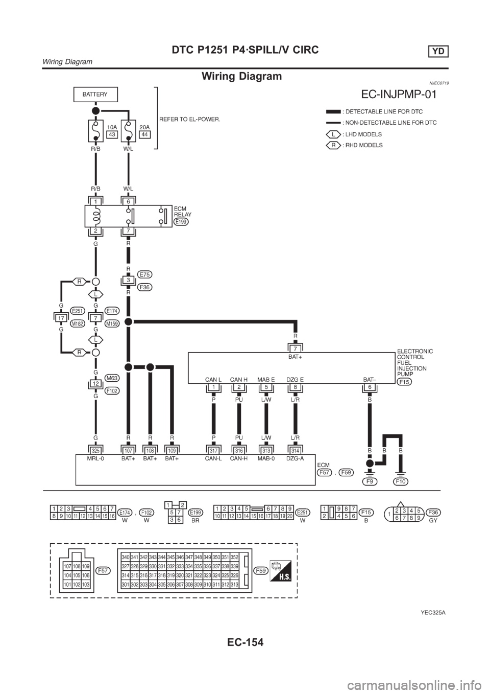
Wiring DiagramNJEC0719
YEC325A
DTC P1251 P4·SPILL/V CIRCYD
Wiring Diagram
EC-154
Page 1209 of 3189
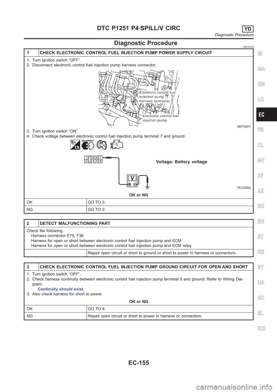
Diagnostic ProcedureNJEC0720
1 CHECK ELECTRONIC CONTROL FUEL INJECTION PUMP POWER SUPPLY CIRCUIT
1. Turn ignition switch “OFF”.
2. Disconnect electronic control fuel injection pump harness connector.
SEF390Y
3. Turn ignition switch “ON”.
4. Check voltage between electronic control fuel injection pump terminal7 and ground.
YEC058A
OK or NG
OK GO TO 3.
NG GO TO 2.
2 DETECT MALFUNCTIONING PART
Check the following.
Harness connector E75, F36
Harness for open or short between electronic control fuel injection pump and ECM
Harness for open or short between electronic control fuel injection pump and ECM relay
Repair open circuit or short to ground or short to power in harness or connectors.
3 CHECK ELECTRONIC CONTROL FUEL INJECTION PUMP GROUND CIRCUIT FOR OPEN ANDSHORT
1. Turn ignition switch “OFF”.
2. Check harness continuity between electronic control fuel injection pump terminal 6 and ground. Refer to Wiring Dia-
gram.
Continuity should exist.
3. Also check harness for short to power.
OK or NG
OK GO TO 4.
NG Repair open circuit or short to power in harness or connectors.
GI
MA
EM
LC
FE
CL
MT
AT
AX
SU
BR
ST
RS
BT
HA
SC
EL
IDX
DTC P1251 P4·SPILL/V CIRCYD
Diagnostic Procedure
EC-155
Page 1210 of 3189
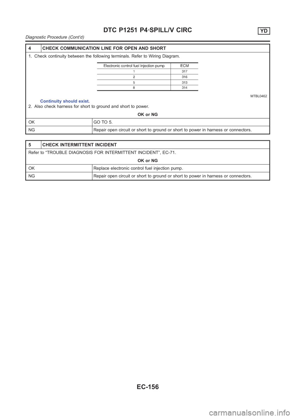
4 CHECK COMMUNICATION LINE FOR OPEN AND SHORT
1. Check continuity between the following terminals. Refer to Wiring Diagram.
MTBL0462
Continuity should exist.
2. Also check harness for short to ground and short to power.
OK or NG
OK GO TO 5.
NG Repair open circuit or short to ground or short to power in harness or connectors.
5 CHECK INTERMITTENT INCIDENT
Refer to “TROUBLE DIAGNOSIS FOR INTERMITTENT INCIDENT”, EC-71.
OK or NG
OK Replace electronic control fuel injection pump.
NG Repair open circuit or short to ground or short to power in harness or connectors.
DTC P1251 P4·SPILL/V CIRCYD
Diagnostic Procedure (Cont’d)
EC-156