position sensor NISSAN ALMERA N16 2003 Electronic Repair Manual
[x] Cancel search | Manufacturer: NISSAN, Model Year: 2003, Model line: ALMERA N16, Model: NISSAN ALMERA N16 2003Pages: 3189, PDF Size: 54.76 MB
Page 5 of 3189

PrecautionsNJGI0001Observe the following precautions to ensure safe and proper
servicing. These precautions are not described in each indi-
vidual section.
SGI646
PRECAUTIONS FOR SUPPLEMENTAL RESTRAINT
SYSTEM (SRS) “AIR BAG” AND “SEAT BELT
PRE-TENSIONER”
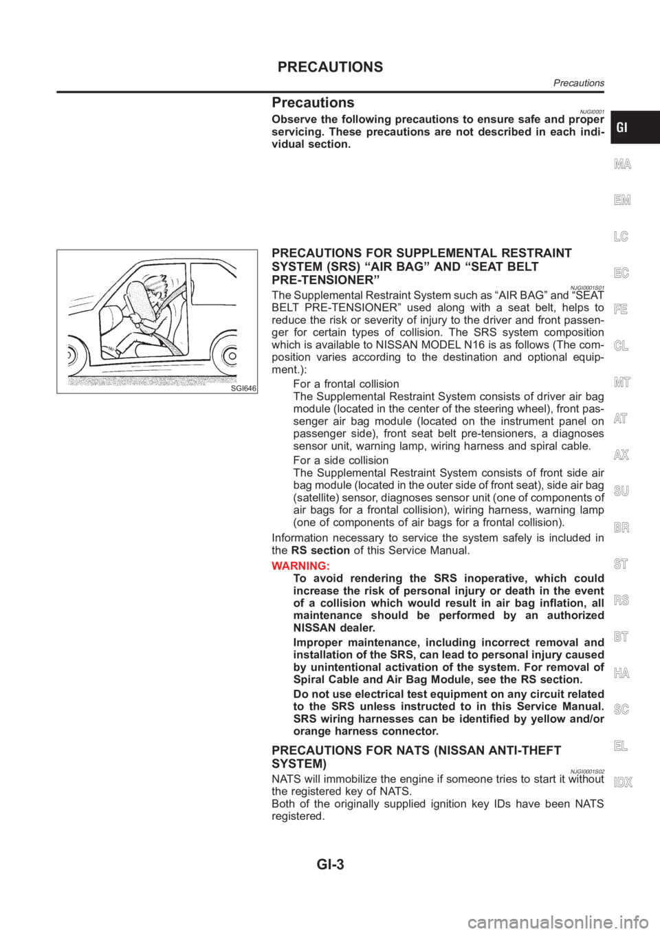
NJGI0001S01The Supplemental Restraint System such as “AIR BAG” and “SEAT
BELT PRE-TENSIONER” used along with a seat belt, helps to
reduce the risk or severity of injury to the driver and front passen-
ger for certain types of collision. The SRS system composition
which is available to NISSAN MODEL N16 is as follows (The com-
position varies according to the destination and optional equip-
ment.):
For a frontal collision
The Supplemental Restraint System consists of driver air bag
module (located in the center of the steering wheel), front pas-
senger air bag module (located on the instrument panel on
passenger side), front seat belt pre-tensioners, a diagnoses
sensor unit, warning lamp, wiring harness and spiral cable.
For a side collision
The Supplemental Restraint System consists of front side air
bag module (located in the outer side of front seat), side air bag
(satellite) sensor, diagnoses sensor unit (one of components of
air bags for a frontal collision), wiring harness, warning lamp
(one of components of air bags for a frontal collision).
Information necessary to service the system safely is included in
theRS sectionof this Service Manual.
WARNING:
To avoid rendering the SRS inoperative, which could
increase the risk of personal injury or death in the event
of a collision which would result in air bag inflation, all
maintenance should be performed by an authorized
NISSAN dealer.
Improper maintenance, including incorrect removal and
installation of the SRS, can lead to personal injury caused
by unintentional activation of the system. For removal of
Spiral Cable and Air Bag Module, see the RS section.
Do not use electrical test equipment on any circuit related
to the SRS unless instructed to in this Service Manual.
SRS wiring harnesses can be identified by yellow and/or
orange harness connector.
PRECAUTIONS FOR NATS (NISSAN ANTI-THEFT
SYSTEM)
NJGI0001S02NATS will immobilize the engine if someone tries to start it without
the registered key of NATS.
Both of the originally supplied ignition key IDs have been NATS
registered.
MA
EM
LC
EC
FE
CL
MT
AT
AX
SU
BR
ST
RS
BT
HA
SC
EL
IDX
PRECAUTIONS
Precautions
GI-3
Page 8 of 3189

Do not attempt to top off the fuel tank after the fuel pump nozzle
shuts off automatically. Continued refueling may cause fuel
overflow, resulting in fuel spray and possibly a fire.
WARNING:
To prevent ECM from storing the diagnostic trouble codes, do
not carelessly disconnect the harness connectors which are
related to the engine control system and TCM (Transmission
Control Module) system. The connectors should be discon-
nected only when working according to the WORK FLOW of
TROUBLE DIAGNOSES in EC and AT sections.
SGI787
PRECAUTIONS FOR MULTIPORT FUEL INJECTION
SYSTEM OR ENGINE CONTROL SYSTEM
NJGI0001S04Before connecting or disconnecting any harness connector for
the multiport fuel injection system or ECM:
Turn ignition switch to “OFF” position.
Disconnect negative battery terminal.
Otherwise, there may be damage to ECM.
Before disconnecting pressurized fuel line from fuel pump to
injectors, be sure to release fuel pressure.
Be careful not to jar components such as ECM and mass air
flow sensor.
PRECAUTIONS FOR THREE WAY CATALYSTNJGI0001S05If a large amount of unburned fuel flows into the catalyst, the cata-
lyst temperature will be excessively high. To prevent this, follow the
instructions below:
Use unleaded gasoline only. Leaded gasoline will seriously
damage the three way catalyst.
When checking for ignition spark or measuring engine
compression, make tests quickly and only when necessary.
Do not run engine when the fuel tank level is low, otherwise the
engine may misfire, causing damage to the catalyst.
Do not place the vehicle on flammable material. Keep flammable
material off the exhaust pipe and the three way catalyst.
SMA019D
PRECAUTIONS FOR HOSESNJGI0001S06Hose Removal and InstallationNJGI0001S0601To prevent damage to rubber hose, do not pry off rubber hose
with tapered tool or screwdriver.
PRECAUTIONS
Precautions (Cont’d)
GI-6
Page 53 of 3189

NJGI0011
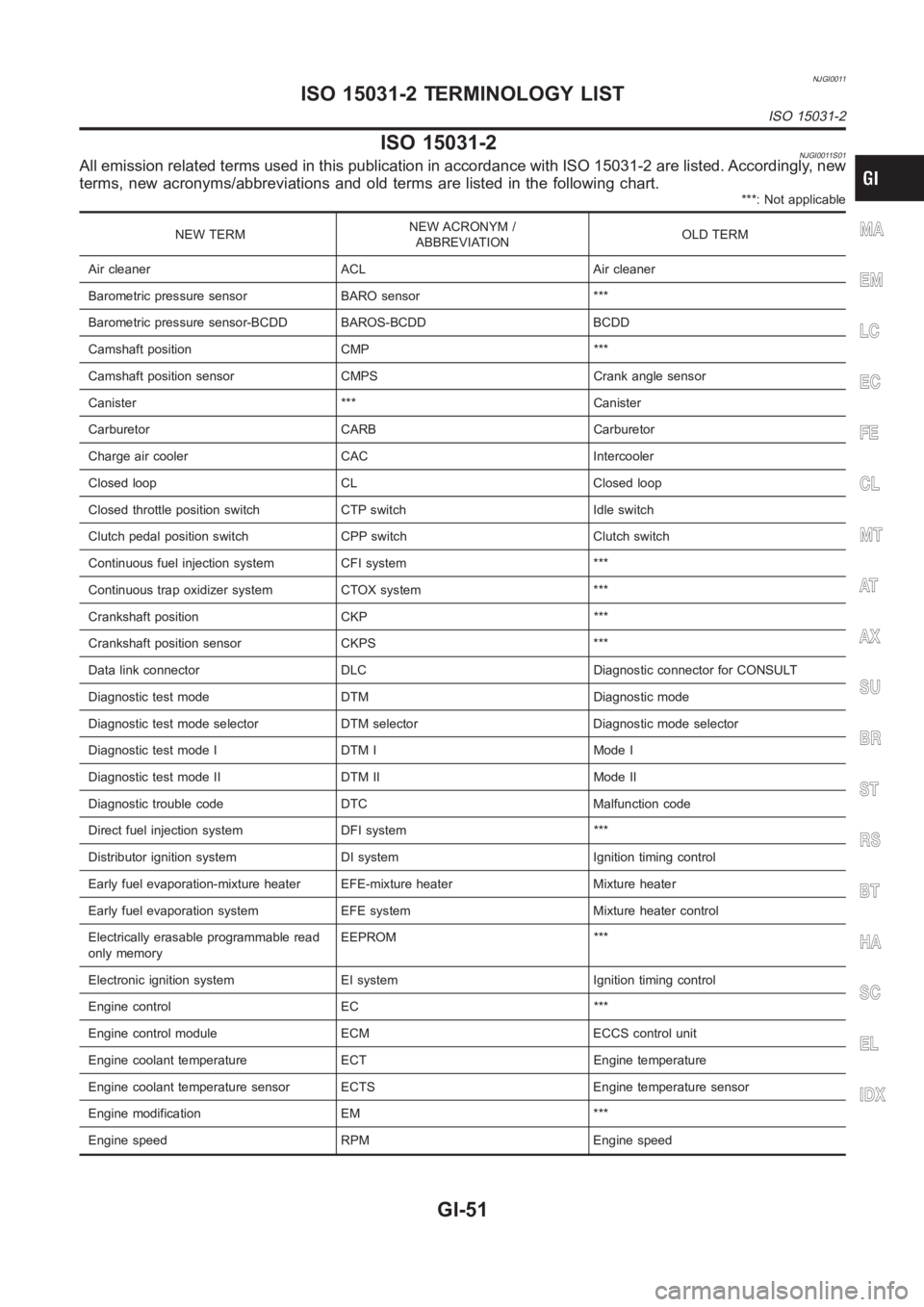
ISO 15031-2NJGI0011S01All emission related terms used in this publication in accordance with ISO15031-2 are listed. Accordingly, new
terms, new acronyms/abbreviations and old terms are listed in the following chart.
***: Not applicable
NEW TERMNEW ACRONYM /
ABBREVIATIONOLD TERM
Air cleaner ACL Air cleaner
Barometric pressure sensor BARO sensor ***
Barometric pressure sensor-BCDD BAROS-BCDD BCDD
Camshaft position CMP ***
Camshaft position sensor CMPS Crank angle sensor
Canister *** Canister
Carburetor CARB Carburetor
Charge air cooler CAC Intercooler
Closed loop CL Closed loop
Closed throttle position switch CTP switch Idle switch
Clutch pedal position switch CPP switch Clutch switch
Continuous fuel injection system CFI system ***
Continuous trap oxidizer system CTOX system ***
Crankshaft position CKP ***
Crankshaft position sensor CKPS ***
Data link connector DLC Diagnostic connector for CONSULT
Diagnostic test mode DTM Diagnostic mode
Diagnostic test mode selector DTM selector Diagnostic mode selector
Diagnostic test mode I DTM I Mode I
Diagnostic test mode II DTM II Mode II
Diagnostic trouble code DTC Malfunction code
Direct fuel injection system DFI system ***
Distributor ignition system DI system Ignition timing control
Early fuel evaporation-mixture heater EFE-mixture heater Mixture heater
Early fuel evaporation system EFE system Mixture heater control
Electrically erasable programmable read
only memoryEEPROM ***
Electronic ignition system EI system Ignition timing control
Engine control EC ***
Engine control module ECM ECCS control unit
Engine coolant temperature ECT Engine temperature
Engine coolant temperature sensor ECTS Engine temperature sensor
Engine modification EM ***
Engine speed RPM Engine speedMA
EM
LC
EC
FE
CL
MT
AT
AX
SU
BR
ST
RS
BT
HA
SC
EL
IDX
ISO 15031-2 TERMINOLOGY LIST
ISO 15031-2
GI-51
Page 55 of 3189

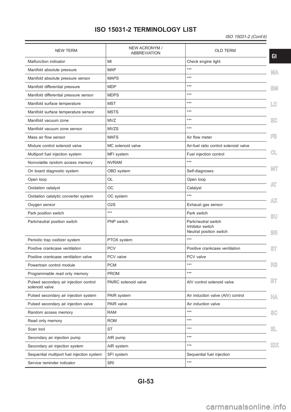
NEW TERMNEW ACRONYM /
ABBREVIATIONOLD TERM
Malfunction indicator MI Check engine light
Manifold absolute pressure MAP ***
Manifold absolute pressure sensor MAPS ***
Manifold differential pressure MDP ***
Manifold differential pressure sensor MDPS ***
Manifold surface temperature MST ***
Manifold surface temperature sensor MSTS ***
Manifold vacuum zone MVZ ***
Manifold vacuum zone sensor MVZS ***
Mass air flow sensor MAFS Air flow meter
Mixture control solenoid valve MC solenoid valve Air-fuel ratio control solenoid valve
Multiport fuel injection system MFI system Fuel injection control
Nonvolatile random access memory NVRAM ***
On board diagnostic system OBD system Self-diagnoses
Open loop OL Open loop
Oxidation catalyst OC Catalyst
Oxidation catalytic converter system OC system ***
Oxygen sensor O2S Exhaust gas sensor
Park position switch *** Park switch
Park/neutral position switch PNP switch Park/neutral switch
Inhibitor switch
Neutral position switch
Periodic trap oxidizer system PTOX system ***
Positive crankcase ventilation PCV Positive crankcase ventilation
Positive crankcase ventilation valve PCV valve PCV valve
Powertrain control module PCM ***
Programmable read only memory PROM ***
Pulsed secondary air injection control
solenoid valvePAIRC solenoid valve AIV control solenoid valve
Pulsed secondary air injection system PAIR system Air induction valve (AIV) control
Pulsed secondary air injection valve PAIR valve Air induction valve
Random access memory RAM ***
Read only memory ROM ***
Scan tool ST ***
Secondary air injection pump AIR pump ***
Secondary air injection system AIR system ***
Sequential multiport fuel injection system SFI system Sequential fuel injection
Service reminder indicator SRI ***
MA
EM
LC
EC
FE
CL
MT
AT
AX
SU
BR
ST
RS
BT
HA
SC
EL
IDX
ISO 15031-2 TERMINOLOGY LIST
ISO 15031-2 (Cont’d)
GI-53
Page 56 of 3189

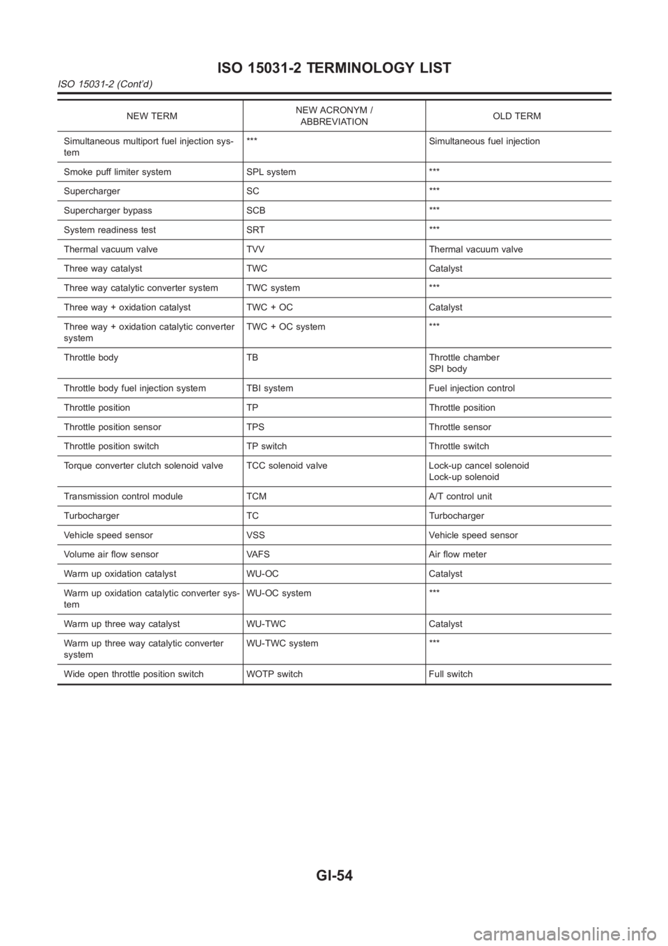
NEW TERMNEW ACRONYM /
ABBREVIATIONOLD TERM
Simultaneous multiport fuel injection sys-
tem*** Simultaneous fuel injection
Smoke puff limiter system SPL system ***
Supercharger SC ***
Supercharger bypass SCB ***
System readiness test SRT ***
Thermal vacuum valve TVV Thermal vacuum valve
Three way catalyst TWC Catalyst
Three way catalytic converter system TWC system ***
Three way + oxidation catalyst TWC + OC Catalyst
Three way + oxidation catalytic converter
systemTWC + OC system ***
Throttle body TB Throttle chamber
SPI body
Throttle body fuel injection system TBI system Fuel injection control
Throttle position TP Throttle position
Throttle position sensor TPS Throttle sensor
Throttle position switch TP switch Throttle switch
Torque converter clutch solenoid valve TCC solenoid valve Lock-up cancelsolenoid
Lock-up solenoid
Transmission control module TCM A/T control unit
Turbocharger TC Turbocharger
Vehicle speed sensor VSS Vehicle speed sensor
Volume air flow sensor VAFS Air flow meter
Warm up oxidation catalyst WU-OC Catalyst
Warm up oxidation catalytic converter sys-
temWU-OC system ***
Warm up three way catalyst WU-TWC Catalyst
Warm up three way catalytic converter
systemWU-TWC system ***
Wide open throttle position switch WOTP switch Full switch
ISO 15031-2 TERMINOLOGY LIST
ISO 15031-2 (Cont’d)
GI-54
Page 107 of 3189
![NISSAN ALMERA N16 2003 Electronic Repair Manual ROCKER COVER
EM-29
[QG]
C
D
E
F
G
H
I
J
K
L
MA
EM
ROCKER COVERPFP:13264
Removal and InstallationEBS00LQA
CAUTION:
Apply new engine oil when installing the parts that specified to do so in the figure.
NISSAN ALMERA N16 2003 Electronic Repair Manual ROCKER COVER
EM-29
[QG]
C
D
E
F
G
H
I
J
K
L
MA
EM
ROCKER COVERPFP:13264
Removal and InstallationEBS00LQA
CAUTION:
Apply new engine oil when installing the parts that specified to do so in the figure.](/img/5/57350/w960_57350-106.png)
ROCKER COVER
EM-29
[QG]
C
D
E
F
G
H
I
J
K
L
MA
EM
ROCKER COVERPFP:13264
Removal and InstallationEBS00LQA
CAUTION:
Apply new engine oil when installing the parts that specified to do so in the figure.
REMOVAL
1. Move harnesses on top surface and right side of rocker cover, and move them aside.
2. Remove ignition coil. Refer to EM-24, "
Removal and Installation" .
3. Disconnect PCV hoses on rocker cover side.
4. If necessary, remove PCV control valve.
5. If necessary, remove intake valve timing control solenoid valve and camshaft position sensor (PHASE).
CAUTION:
●Do not shock it.
●Do not disassemble it.
●Tip of camshaft position sensor (PHASE) generates strong magnetic fields. Keep it away from
metal particles or objects affected by magnetic fields.
KBIA1375E
1. PCV hose 2. Rocker cover 3. Grommet
4. PCV control valve 5. PCV hose 6.Intake valve timing control solenoid
valve
7. O-ring 8. Oil filter cap 9. Gasket
10. Gasket 11. Rocker cover oil seal 12. Gasket
13. O-ring 14. Camshaft position sensor (PHASE)
Page 109 of 3189
![NISSAN ALMERA N16 2003 Electronic Repair Manual ROCKER COVER
EM-31
[QG]
C
D
E
F
G
H
I
J
K
L
MA
EM
d. Tighten mounting screws to specified torque in 2 or more steps
in numerical order shown in figure.
3. Install intake valve timing control NISSAN ALMERA N16 2003 Electronic Repair Manual ROCKER COVER
EM-31
[QG]
C
D
E
F
G
H
I
J
K
L
MA
EM
d. Tighten mounting screws to specified torque in 2 or more steps
in numerical order shown in figure.
3. Install intake valve timing control](/img/5/57350/w960_57350-108.png)
ROCKER COVER
EM-31
[QG]
C
D
E
F
G
H
I
J
K
L
MA
EM
d. Tighten mounting screws to specified torque in 2 or more steps
in numerical order shown in figure.
3. Install intake valve timing control solenoid valve and camshaft position sensor (PHASE).
●Tighten bolt after fully inserting it into rocker cover.
4. Install PCV valve.
●Insert until flange contacts grommet tightly.
5. Install remaining parts in the reverse order of removal.Bolt length: Bolt position
25 mm (0.98 in) : 1
65 mm (2.56 in) : 2
20 mm (0.79 in) : Except the above (all circumference)
KBIA1376E
Page 146 of 3189
![NISSAN ALMERA N16 2003 Electronic Repair Manual EM-68
[QG]
ENGINE ASSEMBLY
WARNING:
●Position vehicle on a flat and solid surface.
●Place chocks at front and back of rear wheels.
●Do not remove engine until exhaust system has complete NISSAN ALMERA N16 2003 Electronic Repair Manual EM-68
[QG]
ENGINE ASSEMBLY
WARNING:
●Position vehicle on a flat and solid surface.
●Place chocks at front and back of rear wheels.
●Do not remove engine until exhaust system has complete](/img/5/57350/w960_57350-145.png)
EM-68
[QG]
ENGINE ASSEMBLY
WARNING:
●Position vehicle on a flat and solid surface.
●Place chocks at front and back of rear wheels.
●Do not remove engine until exhaust system has completely cooled off, otherwise, you may burn
yourself and/or fire may break out in fuel line.
●Before disconnecting fuel hose, release pressure.
Refer to EC-34 (WITH EURO-OBD), EC-428 (WITHOUT EURO-OBD).
●Be sure to lift engine and transaxle in a safe manner.
●For engines not equipped with engine slingers, attach proper slingers and bolts described in
PARTS CATALOG.
CAUTION:
●When lifting engine, be sure to clear surrounding parts. Use special care near accelerator wire
casing, brake lines and brake master cylinder.
●When lifting the engine, always use engine slingers in a safe manner.
●When removing drive shaft, be careful not to damage grease seal of transaxle.
●Before separating engine and transaxle, remove crankshaft position sensor (POS) from the cylin-
der block assembly.
●Always be extra careful not to damage edge of crankshaft position sensor (POS), or signal plate
teeth.
Engine cannot be removed separately from transaxle. Remove engine with transaxle as an assembly.
REMOVAL
1. Drain coolant from radiator and cylinder block. Refer to LC-17, "Chacking Engine Coolant".
2. Remove coolant reservoir tank and bracket.
3. Drain engine oil.
4. Remove battery and battery tray.
5. Remove air cleaner and air duct.
6. Remove drive belts.
7. Remove alternator and air conditioner compressor from engine.
8. Remove power steering oil pump from engine and position aside.
Power steering oil pump does not need to be disconnected from power steering tubes.
9. Remove the following parts:
●RH and LH front tires
●Splash covers
●RH and LH brake caliper assemblies
Refer to BR-28,"Removal".
Brake hose does not need to be disconnected from brake
caliper assembly. Never depress brake pedal.
●RH & LH drive shaft. Refer to AX-11, "Removal".
When removing drive shaft, be careful not to damage
transaxle side grease seal.
●Disconnect control rod and support rod from transaxle. (M/T
models.)
Refer to MT-26, "Removal".
●Disconnect control cable from transaxle. (A/T models.)
Refer to AT-411, "Removal".
SEM174D
SEM109G
Page 149 of 3189
![NISSAN ALMERA N16 2003 Electronic Repair Manual CYLINDER BLOCK
EM-71
[QG]
C
D
E
F
G
H
I
J
K
L
MA
EM
CAUTION:
Apply new engine oil to parts marked in illustration before installation.
DISASSEMBLY
1. Remove engine and transaxle assembly from vehicle, NISSAN ALMERA N16 2003 Electronic Repair Manual CYLINDER BLOCK
EM-71
[QG]
C
D
E
F
G
H
I
J
K
L
MA
EM
CAUTION:
Apply new engine oil to parts marked in illustration before installation.
DISASSEMBLY
1. Remove engine and transaxle assembly from vehicle,](/img/5/57350/w960_57350-148.png)
CYLINDER BLOCK
EM-71
[QG]
C
D
E
F
G
H
I
J
K
L
MA
EM
CAUTION:
Apply new engine oil to parts marked in illustration before installation.
DISASSEMBLY
1. Remove engine and transaxle assembly from vehicle, and separate transaxle from engine. Refer to EM-
67, "ENGINE ASSEMBLY" .
2. Mount engine on an engine stand with the following procedure.
a. Remove exhaust manifold and catalytic converter. Refer to EM-19, "
EXHAUST MANIFOLD AND CATA-
LYTIC CONVERTER" .
b. Remove engine front mounting bracket, alternator and air compressor bracket.
c. Install engine sub-attachment to left side of cylinder block.
d. Lift engine, and mount it onto the engine stand.
1. Rear oil seal 2. Rear oil seal retainer 3. Crankshaft position sensor (POS)
4. O-ring 5. Knock sensor 6. Oil level gauge guide
7. Cylinder block 8. Thrust bearing 9. Main bearing
10. Crankshaft 11. Key 12. Top ring
13. 2nd ring 14. Oil ring 15. Main bearing
16. Piston 17. Snap ring 18. Piston pin
19. Connecting rod 20. Connecting rod bearing 21. Connecting rod cap
22. Connecting rod nut 23. Main bearing cap bolt 24. Baffle plate
25. Main bearing cap 26. Signal plate 27. Rear plate
28. Coolant drain plug 29. Flywheel (M/T models) 30. Drive plate (A/T models)
PBIC0585E
PBIC1017E
Page 150 of 3189
![NISSAN ALMERA N16 2003 Electronic Repair Manual EM-72
[QG]
CYLINDER BLOCK
●A commercial engine stand can be used.
NOTE:
●This example is an engine stand for holding at transaxle
mounting side with the flywheel or drive plate removed.
3 NISSAN ALMERA N16 2003 Electronic Repair Manual EM-72
[QG]
CYLINDER BLOCK
●A commercial engine stand can be used.
NOTE:
●This example is an engine stand for holding at transaxle
mounting side with the flywheel or drive plate removed.
3](/img/5/57350/w960_57350-149.png)
EM-72
[QG]
CYLINDER BLOCK
●A commercial engine stand can be used.
NOTE:
●This example is an engine stand for holding at transaxle
mounting side with the flywheel or drive plate removed.
3. Drain engine oil and coolant from inside of engine.
4. Remove the following components and associated parts.
●Fuel tube and injector assembly; Refer to EM-26, "Removal and Installation" .
●Intake manifold and intake manifold collector assembly; Refer to EM-16, "Removal and Installation" .
●Ignition coil; Refer to EM-24, "Removal and Installation" .
●Rocker cover; Refer to EM-29, "Removal and Installation" .
●Oil pan and oil strainer; Refer to EM-22, "Removal and Installation" .
●Front cover and timing chain; Refer to EM-47, "Removal and Installation" .
●Camshaft; Refer to EM-32, "Removal and Installation" .
●Cylinder head assembly; Refer to EM-58, "Removal and Installation" .
●Auxiliary brackets and oil filter
5. Remove knock sensor.
CAUTION:
Avoid impacts such as a dropping.
6. Remove crankshaft position sensor (POS).
CAUTION:
●Avoid impacts such as a dropping.
●Do not disassemble.
●Keep it away from metal particles.
●Do not place sensor close to magnetic materials.
7. Remove flywheel (M/T models) or drive plate (A/T models). Fix
crankshaft with a ring gear stopper (special service tool), and
remove mounting bolts.
8. Remove rear plate.
9. Remove rear oil seal retainer.
●Insert a flat-bladed screwdriver between main bearing cap
and rear oil seal retainer to remove retainer.
10. Remove rear oil seal from rear oil seal retainer.
●Punch out with a flat-bladed screwdriver.
CAUTION:
●Be careful not to damage rear oil seal retainer.
PBIC0085E
PBIC0586E
SEM880F