oil pressure NISSAN ALMERA TINO 2001 Service Owners Manual
[x] Cancel search | Manufacturer: NISSAN, Model Year: 2001, Model line: ALMERA TINO, Model: NISSAN ALMERA TINO 2001Pages: 3051, PDF Size: 46.38 MB
Page 2713 of 3051

Service Data and Specifications (SDS)
OIL PRESSURE CHECKNLLC0011
Engine speed
rpmApproximate discharge pressure
kPa (bar, kg/cm2, psi)
600 More than 98 (0.98, 1.0, 14)
2,000 More than 294 (2.94, 3.0, 43)
6,000 More than 392 (3.92, 4.0, 57)
OIL PUMP INSPECTIONNLLC0013Unit: mm (in)
Body to outer rotor radial clearance 0.250 - 0.325 (0.0098 - 0.0128)
Inner rotor to outer rotor tip clearance Below 0.18 (0.0071)
Body to inner rotor clearance 0.030 - 0.085 (0.0012 - 0.0033)
Body to outer rotor axial clearance 0.030 - 0.090 (0.0012 - 0.0035)
Inner rotor to brazed portion of housing clearance 0.045 - 0.091 (0.0018 - 0.0036)
REGULATOR VALVE INSPECTIONNLLC0012Unit: mm (in)
Regulator valve to oil pump cover clearance 0.052 - 0.088 (0.0020 - 0.0035)
OIL CAPACITYNLLC0036Unit:!(Imp qt)
With oil filter change2.7 (2-3/8)
Without oil filter change2.5 (2-1/4)
Dry engine (engine overhaul)3.1 (2-3/4)
ENGINE LUBRICATION SYSTEMQG
Service Data and Specifications (SDS)
LC-10
Page 2726 of 3051
SEM164F
AEM080
Precautions
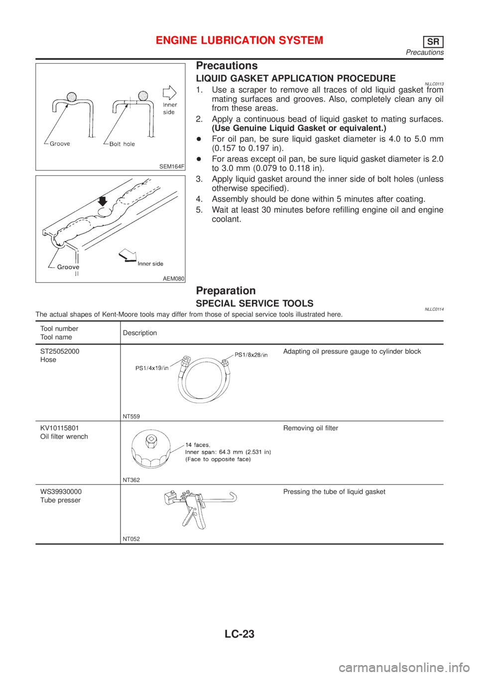
LIQUID GASKET APPLICATION PROCEDURENLLC01131. Use a scraper to remove all traces of old liquid gasket from
mating surfaces and grooves. Also, completely clean any oil
from these areas.
2. Apply a continuous bead of liquid gasket to mating surfaces.
(Use Genuine Liquid Gasket or equivalent.)
+For oil pan, be sure liquid gasket diameter is 4.0 to 5.0 mm
(0.157 to 0.197 in).
+For areas except oil pan, be sure liquid gasket diameter is 2.0
to 3.0 mm (0.079 to 0.118 in).
3. Apply liquid gasket around the inner side of bolt holes (unless
otherwise specified).
4. Assembly should be done within 5 minutes after coating.
5. Wait at least 30 minutes before refilling engine oil and engine
coolant.
Preparation
SPECIAL SERVICE TOOLSNLLC0114The actual shapes of Kent-Moore tools may differ from those of special service tools illustrated here.
Tool number
Tool nameDescription
ST25052000
Hose
NT559
Adapting oil pressure gauge to cylinder block
KV10115801
Oil filter wrench
NT362
Removing oil filter
WS39930000
Tube presser
NT052
Pressing the tube of liquid gasket
ENGINE LUBRICATION SYSTEMSR
Precautions
LC-23
Page 2728 of 3051
NLC045
Oil Pressure CheckNLLC0116WARNING:
+Be careful not to burn yourself, as the engine and oil may
be hot.
+For A/T models, put selector lever in Park ªPº position.
1. Check oil level.
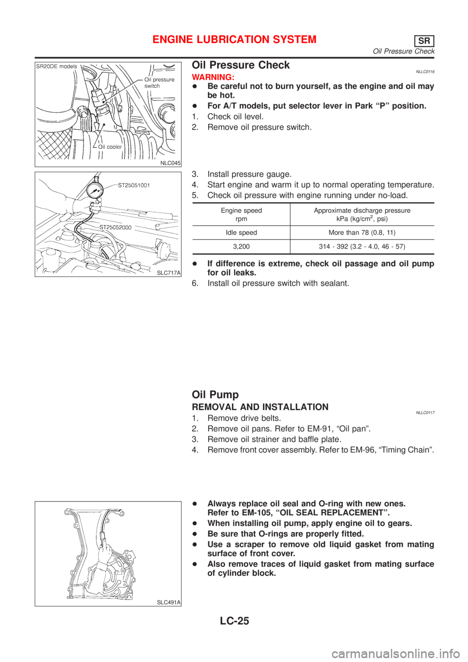
2. Remove oil pressure switch.
SLC717A
3. Install pressure gauge.
4. Start engine and warm it up to normal operating temperature.
5. Check oil pressure with engine running under no-load.
Engine speed
rpmApproximate discharge pressure
kPa (kg/cm2, psi)
Idle speed More than 78 (0.8, 11)
3,200 314 - 392 (3.2 - 4.0, 46 - 57)
+If difference is extreme, check oil passage and oil pump
for oil leaks.
6. Install oil pressure switch with sealant.
Oil Pump
REMOVAL AND INSTALLATIONNLLC01171. Remove drive belts.
2. Remove oil pans. Refer to EM-91, ªOil panº.
3. Remove oil strainer and baffle plate.
4. Remove front cover assembly. Refer to EM-96, ªTiming Chainº.
SLC491A
+Always replace oil seal and O-ring with new ones.
Refer to EM-105, ªOIL SEAL REPLACEMENTº.
+When installing oil pump, apply engine oil to gears.
+Be sure that O-rings are properly fitted.
+Use a scraper to remove old liquid gasket from mating
surface of front cover.
+Also remove traces of liquid gasket from mating surface
of cylinder block.
ENGINE LUBRICATION SYSTEMSR
Oil Pressure Check
LC-25
Page 2730 of 3051
SLC854A
SLC049B
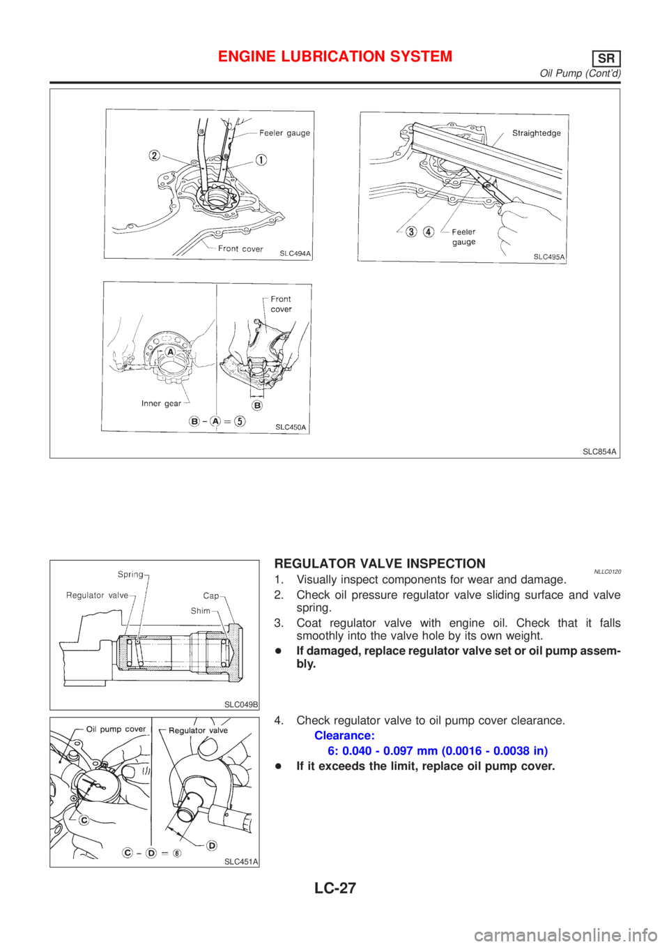
REGULATOR VALVE INSPECTIONNLLC01201. Visually inspect components for wear and damage.
2. Check oil pressure regulator valve sliding surface and valve
spring.
3. Coat regulator valve with engine oil. Check that it falls
smoothly into the valve hole by its own weight.
+If damaged, replace regulator valve set or oil pump assem-
bly.
SLC451A
4. Check regulator valve to oil pump cover clearance.
Clearance:
6: 0.040 - 0.097 mm (0.0016 - 0.0038 in)
+If it exceeds the limit, replace oil pump cover.
ENGINE LUBRICATION SYSTEMSR
Oil Pump (Cont'd)
LC-27
Page 2733 of 3051

1. Drain engine oil and coolant.
2. Remove oil cooler.
3. Installation is in reverse order of removal.
+Be careful not to burn yourself as engine oil is hot.
+After installation, run engine for a few minutes and check
for oil leaks.
+Do not spill coolant on drive belts.
INSPECTIONNLLC01241. Check oil cooler for cracks.
2. Check oil cooler for clogging by blowing through coolant inlet.
If necessary, replace oil cooler assembly.
Service Data and Specifications (SDS)
OIL PRESSURE CHECKNLLC0094
Engine speed
rpmApproximate discharge pressure
kPa (bar, kg/cm2, psi)
Idle speed More than 78 (0.78, 0.80, 11)
3,200 314 - 392 (3.2 - 4.0, 46 - 57)
REGULATOR VALVE INSPECTIONNLLC0096Unit: mm (in)
Regulator valve to oil pump cover clearance 0.040 - 0.097 (0.0016 - 0.0038)
OIL PUMP INSPECTIONNLLC0095Unit: mm (in)
Body to outer rotor radial clearance 0.114 - 0.200 (0.0045 - 0.0079)
Inner gear to outer gear tip clearance Below 0.18 (0.0071)
Body to inner gear clearance 0.05 - 0.09 (0.0020 - 0.0035)
Body to outer gear axial clearance 0.05 - 0.11 (0.0020 - 0.0043)
Inner gear to brazed portion of housing clearance 0.045 - 0.091 (0.0018 - 0.0036)
OIL CAPACITYNLLC0097Unit:!(Imp qt)
With oil filter change3.7 (3-1/4)
Without oil filter change3.5 (3-1/8)
Dry engine (engine overhaul)3.9 (3-3/8)
ENGINE LUBRICATION SYSTEMSR
Oil Cooler (Cont'd)
LC-30
Page 2745 of 3051

SEM164F
AEM080
Precautions
LIQUID GASKET APPLICATION PROCEDURENLLC00391. Use a scraper to remove all traces of old liquid gasket from
mating surfaces and grooves. Also, completely clean any oil
from these areas.
2. Apply a continuous bead of liquid gasket to mating surfaces.
(Use Genuine Liquid Gasket or equivalent.)
+For oil pan, be sure liquid gasket diameter is 4.0 to 5.0 mm
(0.157 to 0.197 in).
+For areas except oil pan, be sure liquid gasket diameter is 2.0
to 3.0 mm (0.079 to 0.118 in).
3. Apply liquid gasket around the inner side of bolt holes (unless
otherwise specified).
4. Assembly should be done within 5 minutes after coating.
5. Wait at least 30 minutes before refilling engine oil and engine
coolant.
Preparation
SPECIAL SERVICE TOOLSNLLC0040
Tool number
Tool nameDescription
ST25051001
Oil pressure gauge
NT050
ST25052000
Hose
NT559
Adapting oil pressure gauge to upper oil pan
WS39930000
Tube presser
NT052
Pressing the tube of liquid gasket
ENGINE LUBRICATION SYSTEMYD
Precautions
LC-42
Page 2747 of 3051
SLC283B
JLC284B
SLC926-A
Oil Pressure CheckNLLC0042WARNING:
+Be careful not to burn yourself, as the engine and oil may
be hot.
+Oil pressure check should be done in ªNeutral positionº.
1. Check oil level.
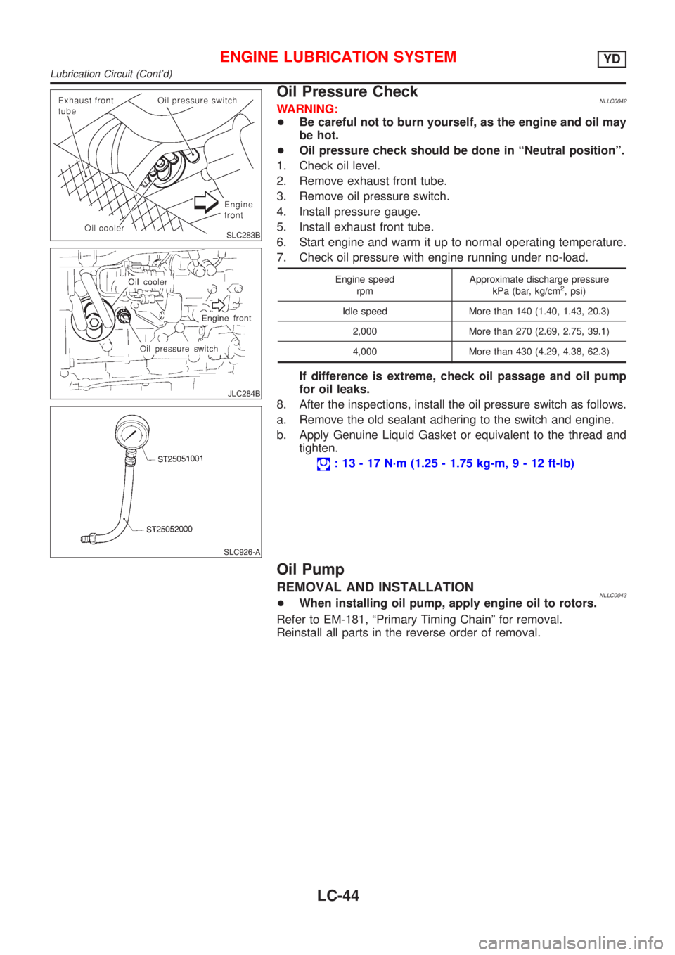
2. Remove exhaust front tube.
3. Remove oil pressure switch.
4. Install pressure gauge.
5. Install exhaust front tube.
6. Start engine and warm it up to normal operating temperature.
7. Check oil pressure with engine running under no-load.
Engine speed
rpmApproximate discharge pressure
kPa (bar, kg/cm2, psi)
Idle speed More than 140 (1.40, 1.43, 20.3)
2,000 More than 270 (2.69, 2.75, 39.1)
4,000 More than 430 (4.29, 4.38, 62.3)
If difference is extreme, check oil passage and oil pump
for oil leaks.
8. After the inspections, install the oil pressure switch as follows.
a. Remove the old sealant adhering to the switch and engine.
b. Apply Genuine Liquid Gasket or equivalent to the thread and
tighten.
: 13 - 17 N´m (1.25 - 1.75 kg-m,9-12ft-lb)
Oil Pump
REMOVAL AND INSTALLATIONNLLC0043+When installing oil pump, apply engine oil to rotors.
Refer to EM-181, ªPrimary Timing Chainº for removal.
Reinstall all parts in the reverse order of removal.
ENGINE LUBRICATION SYSTEMYD
Lubrication Circuit (Cont'd)
LC-44
Page 2749 of 3051

JLC356B
JLC338B
REGULATOR VALVE INSPECTIONNLLC00461. Visually inspect components for wear and damage.
2. Check oil pressure regulator valve sliding surface and valve
spring.
3. Coat regulator valve with engine oil. Check that it falls
smoothly into the valve hole by its own weight.
If damaged, replace regulator valve set or oil pump body.
JLC358B
4. Check regulator valve to oil pump body clearance.
Clearance 6:
6 : 0.040 - 0.097 mm (0.0016 - 0.0038 in)
If it exceeds the limit, replace oil pump body.
ENGINE LUBRICATION SYSTEMYD
Oil Pump (Cont'd)
LC-46
Page 2754 of 3051

Service Data and Specifications (SDS)
OIL PRESSURE CHECK=NLLC0048
Engine speed
rpmApproximate discharge pressure
kPa (bar, kg/cm2, psi)
Idle speed More than 140 (1.40, 1.43, 20.3)
2,000 More than 270 (2.69, 2.75, 39.1)
4,000 More than 430 (4.29, 4.38, 62.3)
REGULATOR VALVE INSPECTIONNLLC0049Unit: mm (in)
Regulator valve to oil pump cover clearance 0.040 - 0.097 (0.0016 - 0.0038)
OIL PUMP INSPECTIONNLLC0050Unit: mm (in)
Body to outer rotor radial clearance 0.114 - 0.260 (0.0045 - 0.0102)
Inner rotor to outer rotor tip clearance Below 0.18 (0.0071)
Body to inner rotor axial clearance 0.050 - 0.090 (0.0020 - 0.0035)
Body to outer rotor axial clearance 0.030 - 0.190 (0.0012 - 0.0075)
Inner rotor to brazed portion of housing clearance 0.045 - 0.091 (0.0018 - 0.0036)
ENGINE OIL CAPACITYNLLC0078Unit:!(Imp qt)
Drain and refill (Approximately)Without oil filter change 4.9 (4-3/8)
With oil filter change 5.2 (4-5/8)
Dry engine (engine overhaul)6.3 (5-1/2)
ENGINE LUBRICATION SYSTEMYD
Service Data and Specifications (SDS)
LC-51
Page 2769 of 3051
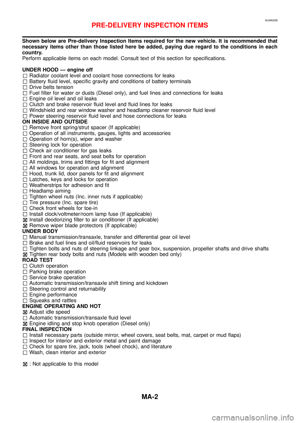
NLMA0036
Shown below are Pre-delivery Inspection Items required for the new vehicle. It is recommended that
necessary items other than those listed here be added, paying due regard to the conditions in each
country.
Perform applicable items on each model. Consult text of this section for specifications.
UNDER HOOD — engine off
Radiator coolant level and coolant hose connections for leaks
Battery fluid level, specific gravity and conditions of battery terminals
Drive belts tension
Fuel filter for water or dusts (Diesel only), and fuel lines and connections for leaks
Engine oil level and oil leaks
Clutch and brake reservoir fluid level and fluid lines for leaks
Windshield and rear window washer and headlamp cleaner reservoir fluid level
Power steering reservoir fluid level and hose connections for leaks
ON INSIDE AND OUTSIDE
Remove front spring/strut spacer (If applicable)
Operation of all instruments, gauges, lights and accessories
Operation of horn(s), wiper and washer
Steering lock for operation
Check air conditioner for gas leaks
Front and rear seats, and seat belts for operation
All moldings, trims and fittings for fit and alignment
All windows for operation and alignment
Hood, trunk lid, door panels for fit and alignment
Latches, keys and locks for operation
Weatherstrips for adhesion and fit
Headlamp aiming
Tighten wheel nuts (Inc. inner nuts if applicable)
Tire pressure (Inc. spare tire)
Check front wheels for toe-in
Install clock/voltmeter/room lamp fuse (If applicable)
Install deodorizing filter to air conditioner (If applicable)
Remove wiper blade protectors (If applicable)
UNDER BODY
Manual transmission/transaxle, transfer and differential gear oil level
Brake and fuel lines and oil/fluid reservoirs for leaks
Tighten bolts and nuts of steering linkage and gear box, suspension, propeller shafts and drive shafts
Tighten rear body bolts and nuts (Models with wooden bed only)
ROAD TEST
Clutch operation
Parking brake operation
Service brake operation
Automatic transmission/transaxle shift timing and kickdown
Steering control and returnability
Engine performance
Squeaks and rattles
ENGINE OPERATING AND HOT
Adjust idle speed
Automatic transmission/transaxle fluid level
Engine idling and stop knob operation (Diesel only)
FINAL INSPECTION
Install necessary parts (outside mirror, wheel covers, seat belts, mat, carpet or mud flaps)
Inspect for interior and exterior metal and paint damage
Check for spare tire, jack, tools (wheel chock), and literature
Wash, clean interior and exterior
: Not applicable to this model
PRE-DELIVERY INSPECTION ITEMS
MA-2