NISSAN ALMERA TINO 2001 Service Repair Manual
Manufacturer: NISSAN, Model Year: 2001, Model line: ALMERA TINO, Model: NISSAN ALMERA TINO 2001Pages: 3051, PDF Size: 46.38 MB
Page 2481 of 3051
+Store the removed parts in sets by the cylinder No. to avoid
mixing them up.
JEM196G
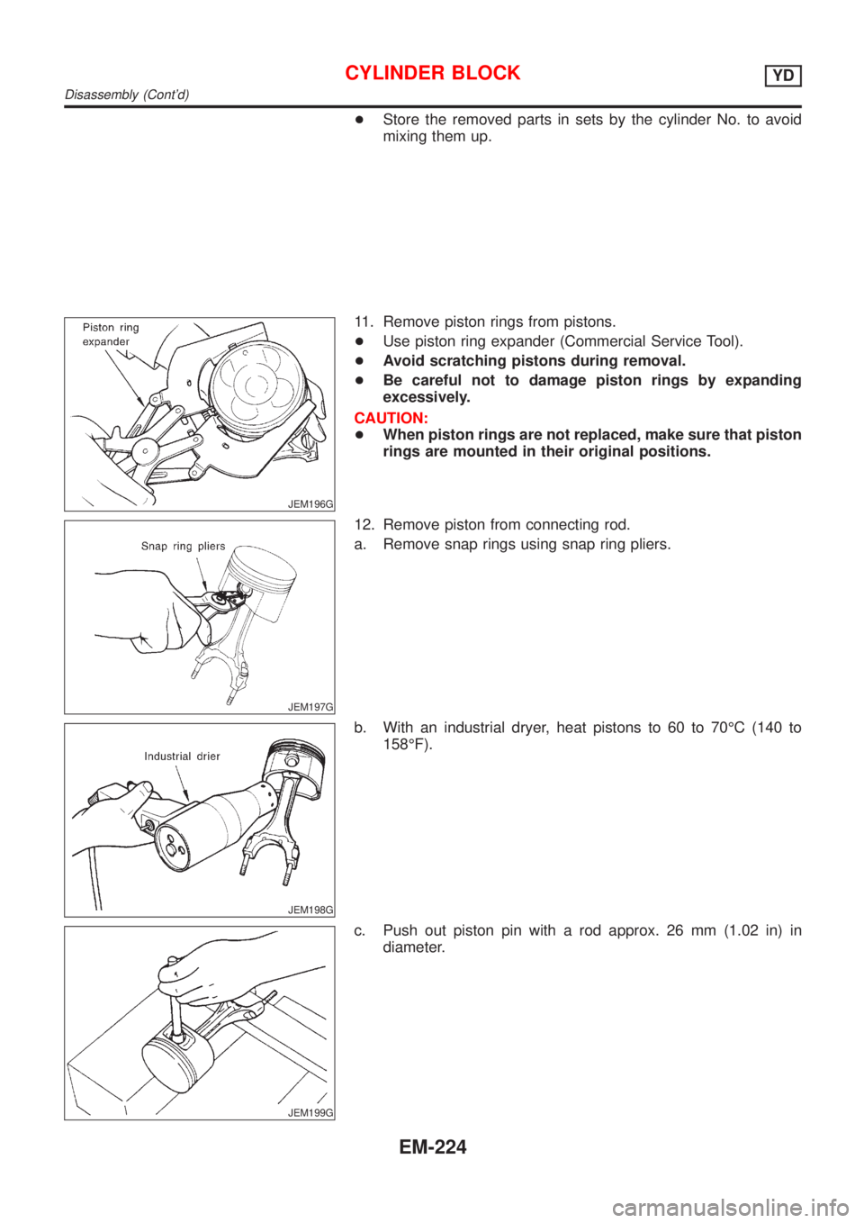
11. Remove piston rings from pistons.
+Use piston ring expander (Commercial Service Tool).
+Avoid scratching pistons during removal.
+Be careful not to damage piston rings by expanding
excessively.
CAUTION:
+When piston rings are not replaced, make sure that piston
rings are mounted in their original positions.
JEM197G
12. Remove piston from connecting rod.
a. Remove snap rings using snap ring pliers.
JEM198G
b. With an industrial dryer, heat pistons to 60 to 70ÉC (140 to
158ÉF).
JEM199G
c. Push out piston pin with a rod approx. 26 mm (1.02 in) in
diameter.
CYLINDER BLOCKYD
Disassembly (Cont'd)
EM-224
Page 2482 of 3051
JEM200G
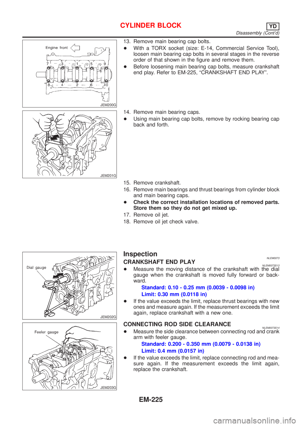
13. Remove main bearing cap bolts.
+With a TORX socket (size: E-14, Commercial Service Tool),
loosen main bearing cap bolts in several stages in the reverse
order of that shown in the figure and remove them.
+Before loosening main bearing cap bolts, measure crankshaft
end play. Refer to EM-225, ªCRANKSHAFT END PLAYº.
JEM201G
14. Remove main bearing caps.
+Using main bearing cap bolts, remove by rocking bearing cap
back and forth.
15. Remove crankshaft.
16. Remove main bearings and thrust bearings from cylinder block
and main bearing caps.
+Check the correct installation locations of removed parts.
Store them so they do not get mixed up.
17. Remove oil jet.
18. Remove oil jet check valve.
JEM202G
InspectionNLEM0073CRANKSHAFT END PLAYNLEM0073S13+Measure the moving distance of the crankshaft with the dial
gauge when the crankshaft is moved fully forward or back-
ward.
Standard: 0.10 - 0.25 mm (0.0039 - 0.0098 in)
Limit: 0.30 mm (0.0118 in)
+If the value exceeds the limit, replace thrust bearings with new
ones and measure again. If the measurement exceeds the limit
again, replace crankshaft with a new one.
JEM203G
CONNECTING ROD SIDE CLEARANCENLEM0073S14+Measure the side clearance between connecting rod and crank
arm with feeler gauge.
Standard: 0.200 - 0.350 mm (0.0079 - 0.0138 in)
Limit: 0.4 mm (0.0157 in)
+If the value exceeds the limit, replace connecting rod and mea-
sure again. If the measurement exceeds the limit again,
replace the crankshaft.
CYLINDER BLOCKYD
Disassembly (Cont'd)
EM-225
Page 2483 of 3051
AEM023
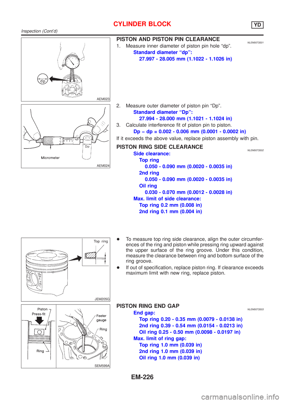
PISTON AND PISTON PIN CLEARANCENLEM0073S011. Measure inner diameter of piston pin hole ªdpº.
Standard diameter ªdpº:
27.997 - 28.005 mm (1.1022 - 1.1026 in)
AEM024
2. Measure outer diameter of piston pin ªDpº.
Standard diameter ªDpº:
27.994 - 28.000 mm (1.1021 - 1.1024 in)
3. Calculate interference fit of piston pin to piston.
Dp þ dp = 0.002 - 0.006 mm (0.0001 - 0.0002 in)
If it exceeds the above value, replace piston assembly with pin.
PISTON RING SIDE CLEARANCENLEM0073S02Side clearance:
Top ring
0.050 - 0.090 mm (0.0020 - 0.0035 in)
2nd ring
0.050 - 0.090 mm (0.0020 - 0.0035 in)
Oil ring
0.030 - 0.070 mm (0.0012 - 0.0028 in)
Max. limit of side clearance:
Top ring 0.2 mm (0.008 in)
2nd ring 0.1 mm (0.004 in)
JEM205G
+To measure top ring side clearance, align the outer circumfer-
ences of the ring and piston while pressing ring upward against
the upper surface of the ring groove. Under this condition,
measure the clearance between ring and bottom surface of the
ring groove.
+If out of specification, replace piston ring. If clearance exceeds
maximum limit with new ring, replace piston.
SEM599A
PISTON RING END GAPNLEM0073S03End gap:
Top ring 0.20 - 0.35 mm (0.0079 - 0.0138 in)
2nd ring 0.39 - 0.54 mm (0.0154 - 0.0213 in)
Oil ring 0.25 - 0.50 mm (0.0098 - 0.0197 in)
Max. limit of ring gap:
Top ring 1.0 mm (0.039 in)
2nd ring 1.0 mm (0.039 in)
Oil ring 1.0 mm (0.039 in)
CYLINDER BLOCKYD
Inspection (Cont'd)
EM-226
Page 2484 of 3051
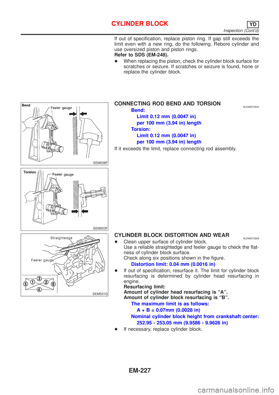
If out of specification, replace piston ring. If gap still exceeds the
limit even with a new ring, do the following. Rebore cylinder and
use oversized piston and piston rings.
Refer to SDS (EM-248).
+When replacing the piston, check the cylinder block surface for
scratches or seizure. If scratches or seizure is found, hone or
replace the cylinder block.
SEM038F
SEM003F
CONNECTING ROD BEND AND TORSIONNLEM0073S04Bend:
Limit 0.12 mm (0.0047 in)
per 100 mm (3.94 in) length
Torsion:
Limit 0.12 mm (0.0047 in)
per 100 mm (3.94 in) length
If it exceeds the limit, replace connecting rod assembly.
SEM501G
CYLINDER BLOCK DISTORTION AND WEARNLEM0073S05+Clean upper surface of cylinder block.
Use a reliable straightedge and feeler gauge to check the flat-
ness of cylinder block surface.
Check along six positions shown in the figure.
Distortion limit: 0.04 mm (0.0016 in)
+If out of specification, resurface it. The limit for cylinder block
resurfacing is determined by cylinder head resurfacing in
engine.
Resurfacing limit:
Amount of cylinder head resurfacing is ªAº.
Amount of cylinder block resurfacing is ªBº.
The maximum limit is as follows:
A + B = 0.07mm (0.0028 in)
Nominal cylinder block height from crankshaft center:
252.95 - 253.05 mm (9.9586 - 9.9626 in)
+If necessary, replace cylinder block.
CYLINDER BLOCKYD
Inspection (Cont'd)
EM-227
Page 2485 of 3051
JEM206G
JEM207G
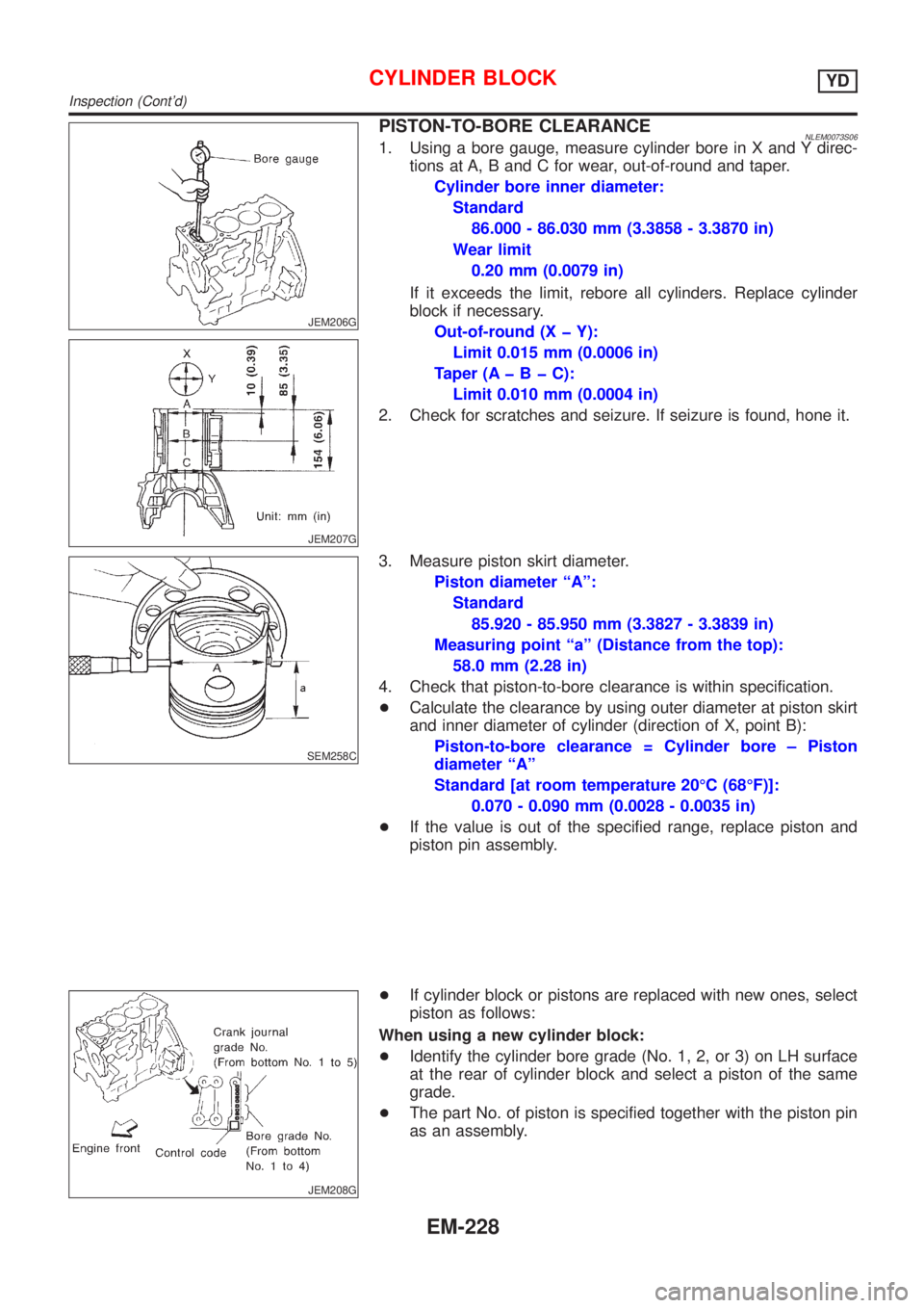
PISTON-TO-BORE CLEARANCENLEM0073S061. Using a bore gauge, measure cylinder bore in X and Y direc-
tions at A, B and C for wear, out-of-round and taper.
Cylinder bore inner diameter:
Standard
86.000 - 86.030 mm (3.3858 - 3.3870 in)
Wear limit
0.20 mm (0.0079 in)
If it exceeds the limit, rebore all cylinders. Replace cylinder
block if necessary.
Out-of-round (X þ Y):
Limit 0.015 mm (0.0006 in)
Taper (AþBþC):
Limit 0.010 mm (0.0004 in)
2. Check for scratches and seizure. If seizure is found, hone it.
SEM258C
3. Measure piston skirt diameter.
Piston diameter ªAº:
Standard
85.920 - 85.950 mm (3.3827 - 3.3839 in)
Measuring point ªaº (Distance from the top):
58.0 mm (2.28 in)
4. Check that piston-to-bore clearance is within specification.
+Calculate the clearance by using outer diameter at piston skirt
and inner diameter of cylinder (direction of X, point B):
Piston-to-bore clearance = Cylinder bore ± Piston
diameter ªAº
Standard [at room temperature 20ÉC (68ÉF)]:
0.070 - 0.090 mm (0.0028 - 0.0035 in)
+If the value is out of the specified range, replace piston and
piston pin assembly.
JEM208G
+If cylinder block or pistons are replaced with new ones, select
piston as follows:
When using a new cylinder block:
+Identify the cylinder bore grade (No. 1, 2, or 3) on LH surface
at the rear of cylinder block and select a piston of the same
grade.
+The part No. of piston is specified together with the piston pin
as an assembly.
CYLINDER BLOCKYD
Inspection (Cont'd)
EM-228
Page 2486 of 3051
SEM509G
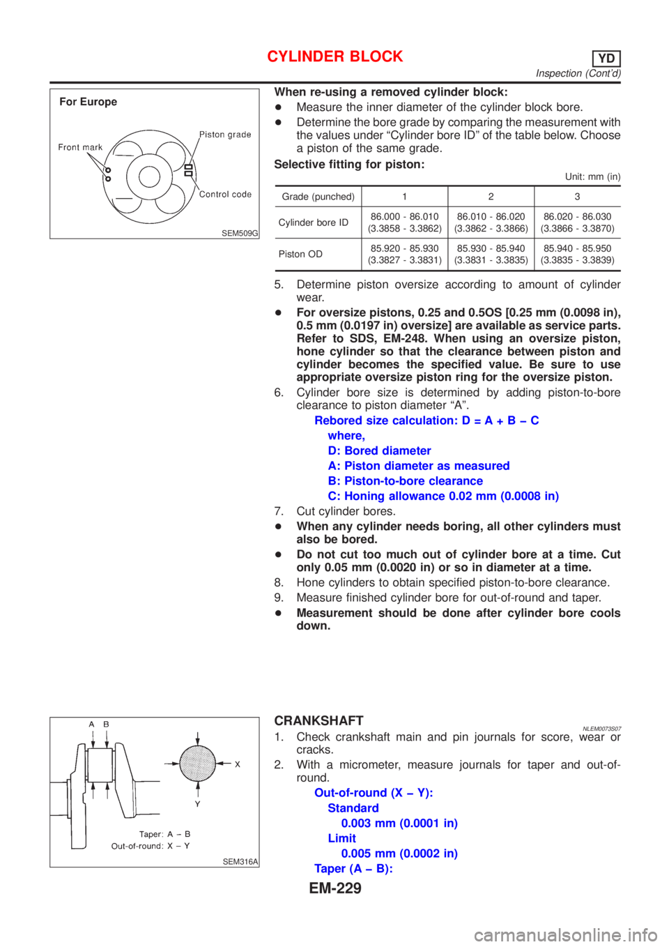
When re-using a removed cylinder block:
+Measure the inner diameter of the cylinder block bore.
+Determine the bore grade by comparing the measurement with
the values under ªCylinder bore IDº of the table below. Choose
a piston of the same grade.
Selective fitting for piston:
Unit: mm (in)
Grade (punched) 1 2 3
Cylinder bore ID86.000 - 86.010
(3.3858 - 3.3862)86.010 - 86.020
(3.3862 - 3.3866)86.020 - 86.030
(3.3866 - 3.3870)
Piston OD85.920 - 85.930
(3.3827 - 3.3831)85.930 - 85.940
(3.3831 - 3.3835)85.940 - 85.950
(3.3835 - 3.3839)
5. Determine piston oversize according to amount of cylinder
wear.
+For oversize pistons, 0.25 and 0.5OS [0.25 mm (0.0098 in),
0.5 mm (0.0197 in) oversize] are available as service parts.
Refer to SDS, EM-248. When using an oversize piston,
hone cylinder so that the clearance between piston and
cylinder becomes the specified value. Be sure to use
appropriate oversize piston ring for the oversize piston.
6. Cylinder bore size is determined by adding piston-to-bore
clearance to piston diameter ªAº.
Rebored size calculation: D = A+BþC
where,
D: Bored diameter
A: Piston diameter as measured
B: Piston-to-bore clearance
C: Honing allowance 0.02 mm (0.0008 in)
7. Cut cylinder bores.
+When any cylinder needs boring, all other cylinders must
also be bored.
+Do not cut too much out of cylinder bore at a time. Cut
only 0.05 mm (0.0020 in) or so in diameter at a time.
8. Hone cylinders to obtain specified piston-to-bore clearance.
9. Measure finished cylinder bore for out-of-round and taper.
+Measurement should be done after cylinder bore cools
down.
SEM316A
CRANKSHAFTNLEM0073S071. Check crankshaft main and pin journals for score, wear or
cracks.
2. With a micrometer, measure journals for taper and out-of-
round.
Out-of-round (X þ Y):
Standard
0.003 mm (0.0001 in)
Limit
0.005 mm (0.0002 in)
Taper (A þ B):
CYLINDER BLOCKYD
Inspection (Cont'd)
EM-229
Page 2487 of 3051
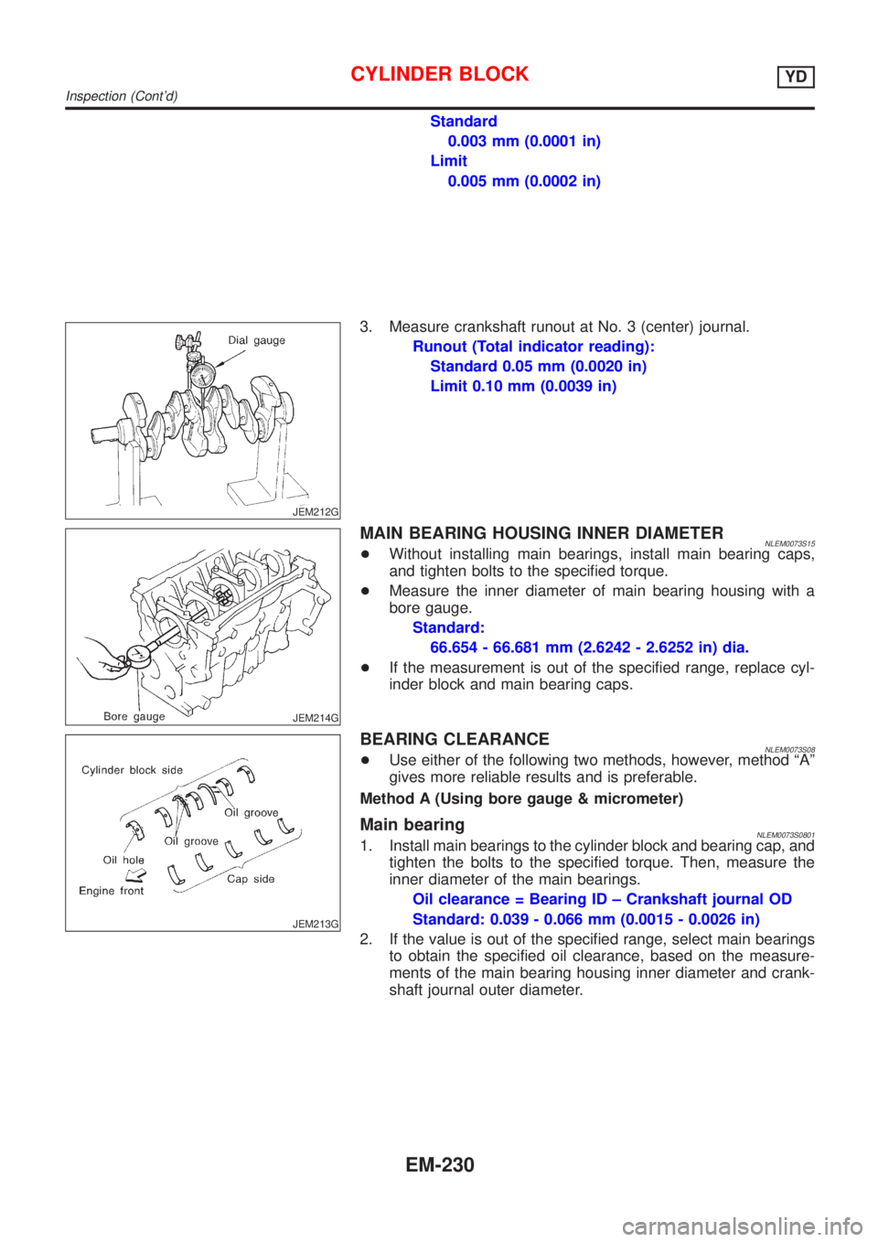
Standard
0.003 mm (0.0001 in)
Limit
0.005 mm (0.0002 in)
JEM212G
3. Measure crankshaft runout at No. 3 (center) journal.
Runout (Total indicator reading):
Standard 0.05 mm (0.0020 in)
Limit 0.10 mm (0.0039 in)
JEM214G
MAIN BEARING HOUSING INNER DIAMETERNLEM0073S15+Without installing main bearings, install main bearing caps,
and tighten bolts to the specified torque.
+Measure the inner diameter of main bearing housing with a
bore gauge.
Standard:
66.654 - 66.681 mm (2.6242 - 2.6252 in) dia.
+If the measurement is out of the specified range, replace cyl-
inder block and main bearing caps.
JEM213G
BEARING CLEARANCENLEM0073S08+Use either of the following two methods, however, method ªAº
gives more reliable results and is preferable.
Method A (Using bore gauge & micrometer)
Main bearingNLEM0073S08011. Install main bearings to the cylinder block and bearing cap, and
tighten the bolts to the specified torque. Then, measure the
inner diameter of the main bearings.
Oil clearance = Bearing ID ± Crankshaft journal OD
Standard: 0.039 - 0.066 mm (0.0015 - 0.0026 in)
2. If the value is out of the specified range, select main bearings
to obtain the specified oil clearance, based on the measure-
ments of the main bearing housing inner diameter and crank-
shaft journal outer diameter.
CYLINDER BLOCKYD
Inspection (Cont'd)
EM-230
Page 2488 of 3051
JEM208G
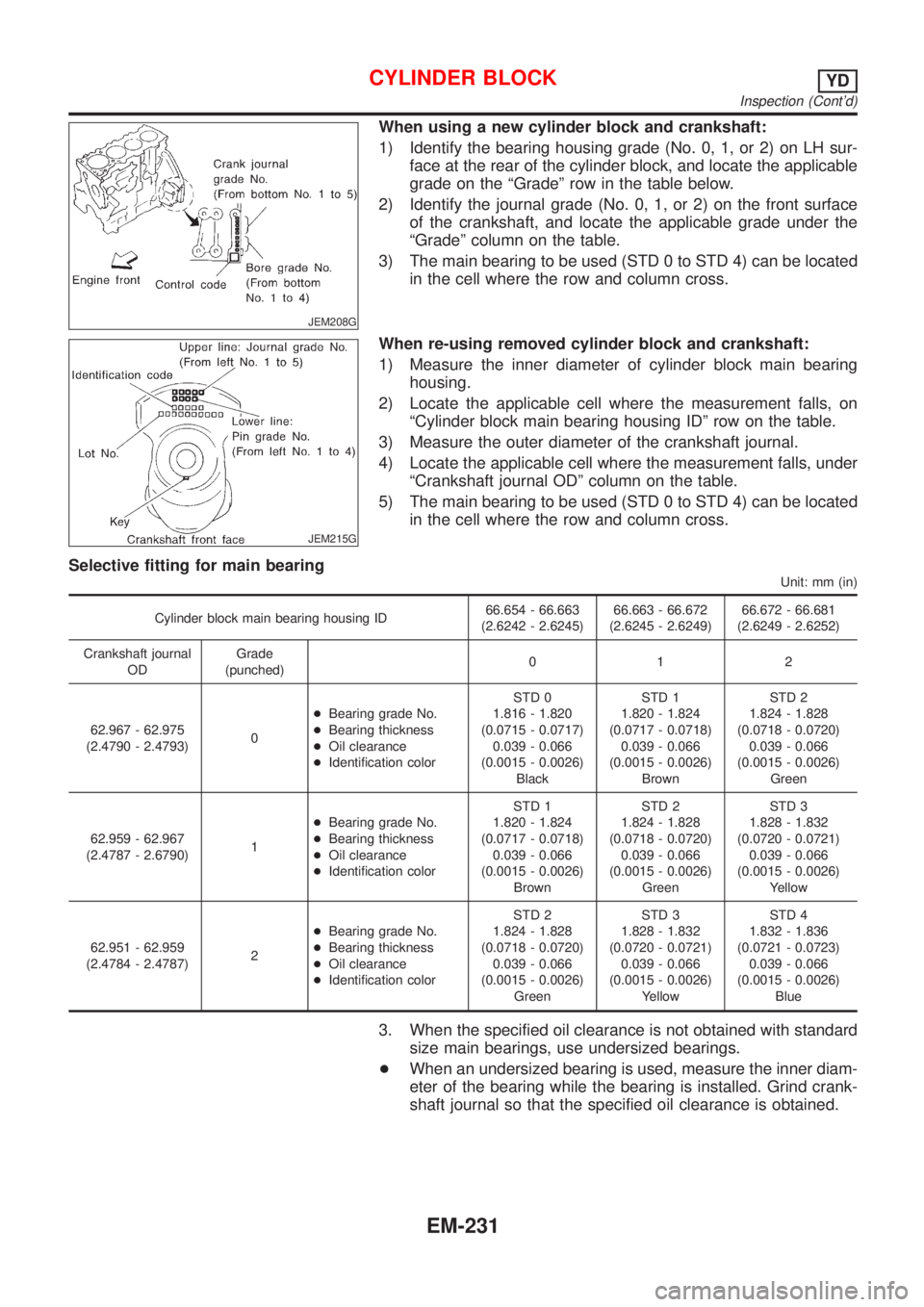
When using a new cylinder block and crankshaft:
1) Identify the bearing housing grade (No. 0, 1, or 2) on LH sur-
face at the rear of the cylinder block, and locate the applicable
grade on the ªGradeº row in the table below.
2) Identify the journal grade (No. 0, 1, or 2) on the front surface
of the crankshaft, and locate the applicable grade under the
ªGradeº column on the table.
3) The main bearing to be used (STD 0 to STD 4) can be located
in the cell where the row and column cross.
JEM215G
When re-using removed cylinder block and crankshaft:
1) Measure the inner diameter of cylinder block main bearing
housing.
2) Locate the applicable cell where the measurement falls, on
ªCylinder block main bearing housing IDº row on the table.
3) Measure the outer diameter of the crankshaft journal.
4) Locate the applicable cell where the measurement falls, under
ªCrankshaft journal ODº column on the table.
5) The main bearing to be used (STD 0 to STD 4) can be located
in the cell where the row and column cross.
Selective fitting for main bearing
Unit: mm (in)
Cylinder block main bearing housing ID66.654 - 66.663
(2.6242 - 2.6245)66.663 - 66.672
(2.6245 - 2.6249)66.672 - 66.681
(2.6249 - 2.6252)
Crankshaft journal
ODGrade
(punched)012
62.967 - 62.975
(2.4790 - 2.4793)0+Bearing grade No.
+Bearing thickness
+Oil clearance
+Identification colorSTD 0
1.816 - 1.820
(0.0715 - 0.0717)
0.039 - 0.066
(0.0015 - 0.0026)
BlackSTD 1
1.820 - 1.824
(0.0717 - 0.0718)
0.039 - 0.066
(0.0015 - 0.0026)
BrownSTD 2
1.824 - 1.828
(0.0718 - 0.0720)
0.039 - 0.066
(0.0015 - 0.0026)
Green
62.959 - 62.967
(2.4787 - 2.6790)1+Bearing grade No.
+Bearing thickness
+Oil clearance
+Identification colorSTD 1
1.820 - 1.824
(0.0717 - 0.0718)
0.039 - 0.066
(0.0015 - 0.0026)
BrownSTD 2
1.824 - 1.828
(0.0718 - 0.0720)
0.039 - 0.066
(0.0015 - 0.0026)
GreenSTD 3
1.828 - 1.832
(0.0720 - 0.0721)
0.039 - 0.066
(0.0015 - 0.0026)
Yellow
62.951 - 62.959
(2.4784 - 2.4787)2+Bearing grade No.
+Bearing thickness
+Oil clearance
+Identification colorSTD 2
1.824 - 1.828
(0.0718 - 0.0720)
0.039 - 0.066
(0.0015 - 0.0026)
GreenSTD 3
1.828 - 1.832
(0.0720 - 0.0721)
0.039 - 0.066
(0.0015 - 0.0026)
YellowSTD 4
1.832 - 1.836
(0.0721 - 0.0723)
0.039 - 0.066
(0.0015 - 0.0026)
Blue
3. When the specified oil clearance is not obtained with standard
size main bearings, use undersized bearings.
+When an undersized bearing is used, measure the inner diam-
eter of the bearing while the bearing is installed. Grind crank-
shaft journal so that the specified oil clearance is obtained.
CYLINDER BLOCKYD
Inspection (Cont'd)
EM-231
Page 2489 of 3051
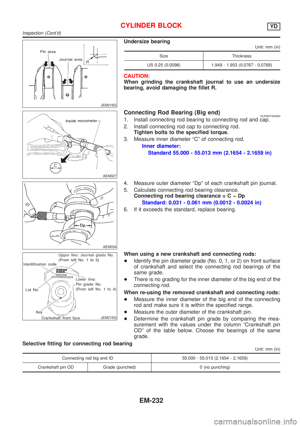
JEM216G
Undersize bearing
Unit: mm (in)
Size Thickness
US 0.25 (0.0098) 1.949 - 1.953 (0.0767 - 0.0769)
CAUTION:
When grinding the crankshaft journal to use an undersize
bearing, avoid damaging the fillet R.
AEM027
Connecting Rod Bearing (Big end)NLEM0073S08021. Install connecting rod bearing to connecting rod and cap.
2. Install connecting rod cap to connecting rod.
Tighten bolts to the specified torque.
3. Measure inner diameter ªCº of connecting rod.
Inner diameter:
Standard 55.000 - 55.013 mm (2.1654 - 2.1659 in)
AEM034
4. Measure outer diameter ªDpº of each crankshaft pin journal.
5. Calculate connecting rod bearing clearance.
Connecting rod bearing clearance=CþDp
Standard: 0.031 - 0.061 mm (0.0012 - 0.0024 in)
6. If it exceeds the standard, replace bearing.
JEM215G
When using a new crankshaft and connecting rods:
+Identify the pin diameter grade (No. 0, 1, or 2) on front surface
of crankshaft and select the connecting rod bearings of the
same grade.
+There is no grading for the inner diameter of the big end of the
connecting rod.
When re-using the removed crankshaft and connecting rods:
+Measure the inner diameter of the big end of the connecting
rod and make sure it is within the specified range.
+Measure the outer diameter of the crankshaft pin.
+Determine the crankshaft pin grade by comparing the mea-
surement with the values under the column ªCrankshaft pin
ODº of the table below. Choose the bearings of the same
grade.
Selective fitting for connecting rod bearing
Unit: mm (in)
Connecting rod big end ID 55.000 - 55.013 (2.1654 - 2.1659)
Crankshaft pin OD Grade (punched) 0 (no punching)
CYLINDER BLOCKYD
Inspection (Cont'd)
EM-232
Page 2490 of 3051
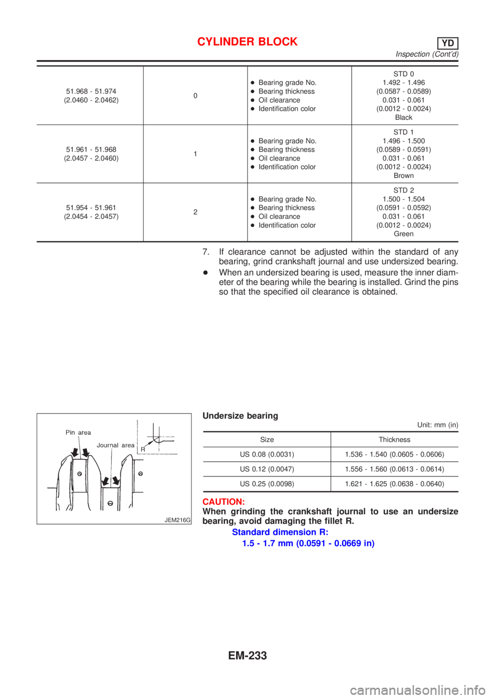
51.968 - 51.974
(2.0460 - 2.0462)0+Bearing grade No.
+Bearing thickness
+Oil clearance
+Identification colorSTD 0
1.492 - 1.496
(0.0587 - 0.0589)
0.031 - 0.061
(0.0012 - 0.0024)
Black
51.961 - 51.968
(2.0457 - 2.0460)1+Bearing grade No.
+Bearing thickness
+Oil clearance
+Identification colorSTD 1
1.496 - 1.500
(0.0589 - 0.0591)
0.031 - 0.061
(0.0012 - 0.0024)
Brown
51.954 - 51.961
(2.0454 - 2.0457)2+Bearing grade No.
+Bearing thickness
+Oil clearance
+Identification colorSTD 2
1.500 - 1.504
(0.0591 - 0.0592)
0.031 - 0.061
(0.0012 - 0.0024)
Green
7. If clearance cannot be adjusted within the standard of any
bearing, grind crankshaft journal and use undersized bearing.
+When an undersized bearing is used, measure the inner diam-
eter of the bearing while the bearing is installed. Grind the pins
so that the specified oil clearance is obtained.
JEM216G
Undersize bearing
Unit: mm (in)
Size Thickness
US 0.08 (0.0031) 1.536 - 1.540 (0.0605 - 0.0606)
US 0.12 (0.0047) 1.556 - 1.560 (0.0613 - 0.0614)
US 0.25 (0.0098) 1.621 - 1.625 (0.0638 - 0.0640)
CAUTION:
When grinding the crankshaft journal to use an undersize
bearing, avoid damaging the fillet R.
Standard dimension R:
1.5 - 1.7 mm (0.0591 - 0.0669 in)
CYLINDER BLOCKYD
Inspection (Cont'd)
EM-233