NISSAN ALMERA TINO 2001 Service Repair Manual
Manufacturer: NISSAN, Model Year: 2001, Model line: ALMERA TINO, Model: NISSAN ALMERA TINO 2001Pages: 3051, PDF Size: 46.38 MB
Page 471 of 3051
SEF058Y
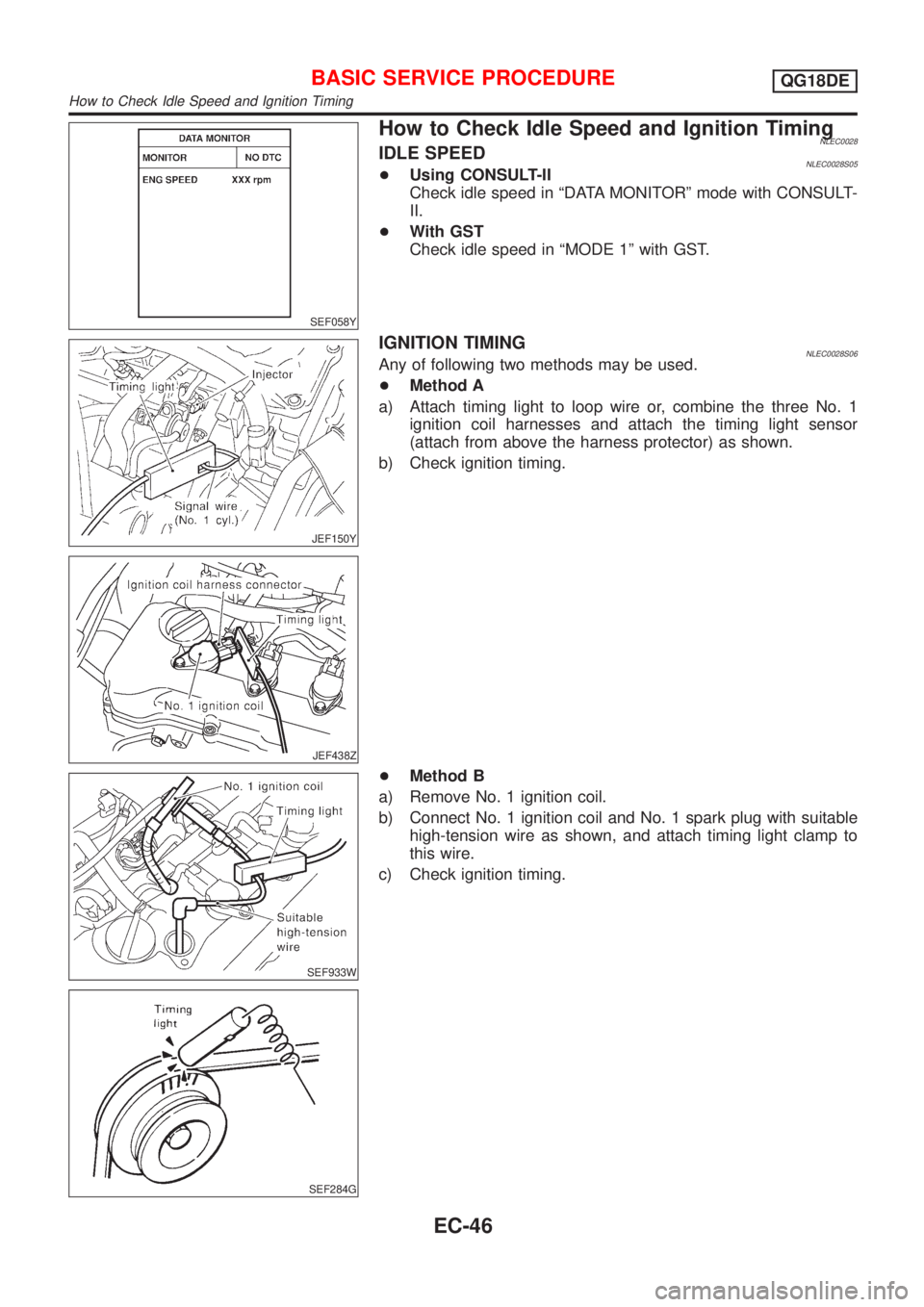
How to Check Idle Speed and Ignition TimingNLEC0028IDLE SPEEDNLEC0028S05+Using CONSULT-II
Check idle speed in ªDATA MONITORº mode with CONSULT-
II.
+With GST
Check idle speed in ªMODE 1º with GST.
JEF150Y
JEF438Z
IGNITION TIMINGNLEC0028S06Any of following two methods may be used.
+Method A
a) Attach timing light to loop wire or, combine the three No. 1
ignition coil harnesses and attach the timing light sensor
(attach from above the harness protector) as shown.
b) Check ignition timing.
SEF933W
SEF284G
+Method B
a) Remove No. 1 ignition coil.
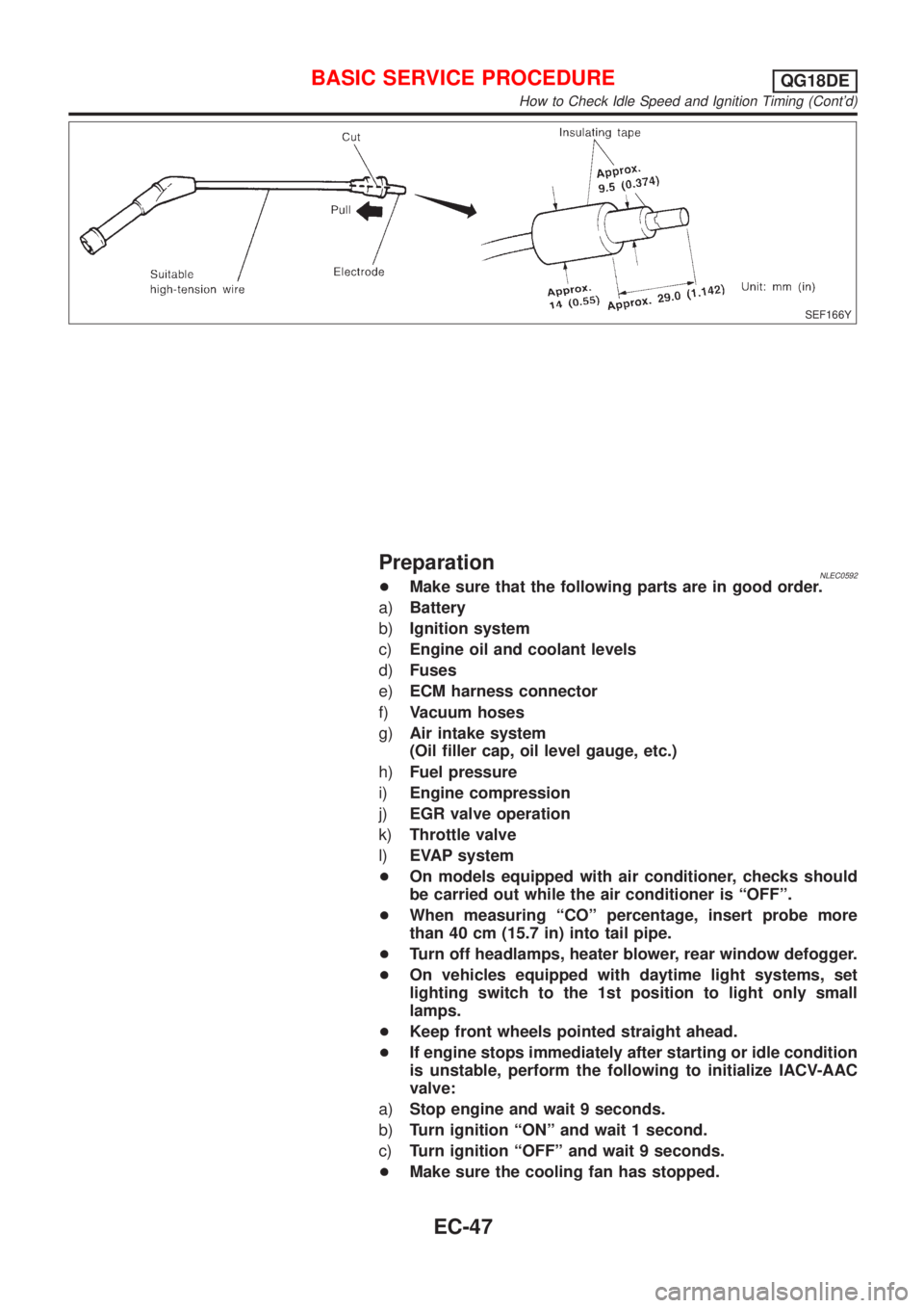
b) Connect No. 1 ignition coil and No. 1 spark plug with suitable
high-tension wire as shown, and attach timing light clamp to
this wire.
c) Check ignition timing.
BASIC SERVICE PROCEDUREQG18DE
How to Check Idle Speed and Ignition Timing
EC-46
Page 472 of 3051
SEF166Y
PreparationNLEC0592+Make sure that the following parts are in good order.
a)Battery
b)Ignition system
c)Engine oil and coolant levels
d)Fuses
e)ECM harness connector
f)Vacuum hoses
g)Air intake system
(Oil filler cap, oil level gauge, etc.)
h)Fuel pressure
i)Engine compression
j)EGR valve operation
k)Throttle valve
l)EVAP system
+On models equipped with air conditioner, checks should
be carried out while the air conditioner is ªOFFº.
+When measuring ªCOº percentage, insert probe more
than 40 cm (15.7 in) into tail pipe.
+Turn off headlamps, heater blower, rear window defogger.
+On vehicles equipped with daytime light systems, set
lighting switch to the 1st position to light only small
lamps.
+Keep front wheels pointed straight ahead.
+If engine stops immediately after starting or idle condition
is unstable, perform the following to initialize IACV-AAC
valve:
a)Stop engine and wait 9 seconds.
b)Turn ignition ªONº and wait 1 second.
c)Turn ignition ªOFFº and wait 9 seconds.
+Make sure the cooling fan has stopped.
BASIC SERVICE PROCEDUREQG18DE
How to Check Idle Speed and Ignition Timing (Cont'd)
EC-47
Page 473 of 3051
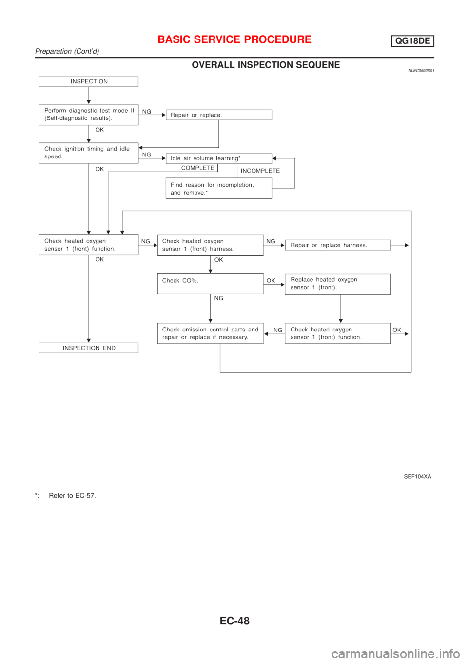
OVERALL INSPECTION SEQUENENLEC0592S01
SEF104XA
*: Refer to EC-57.
BASIC SERVICE PROCEDUREQG18DE
Preparation (Cont'd)
EC-48
Page 474 of 3051
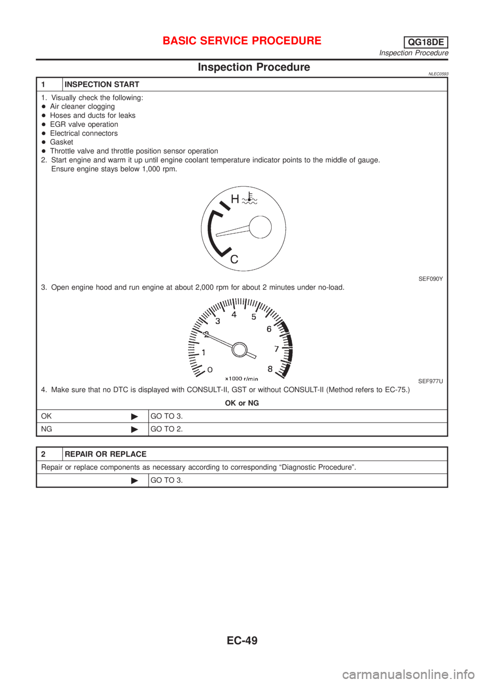
Inspection ProcedureNLEC0593
1 INSPECTION START
1. Visually check the following:
+Air cleaner clogging
+Hoses and ducts for leaks
+EGR valve operation
+Electrical connectors
+Gasket
+Throttle valve and throttle position sensor operation
2. Start engine and warm it up until engine coolant temperature indicator points to the middle of gauge.
Ensure engine stays below 1,000 rpm.
SEF090Y
3. Open engine hood and run engine at about 2,000 rpm for about 2 minutes under no-load.
SEF977U
4. Make sure that no DTC is displayed with CONSULT-II, GST or without CONSULT-II (Method refers to EC-75.)
OK or NG
OK©GO TO 3.
NG©GO TO 2.
2 REPAIR OR REPLACE
Repair or replace components as necessary according to corresponding ªDiagnostic Procedureº.
©GO TO 3.
BASIC SERVICE PROCEDUREQG18DE
Inspection Procedure
EC-49
Page 475 of 3051
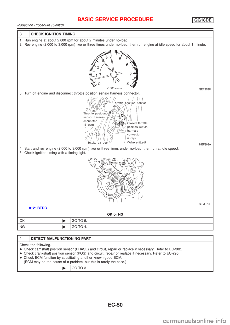
3 CHECK IGNITION TIMING
1. Run engine at about 2,000 rpm for about 2 minutes under no-load.
2. Rev engine (2,000 to 3,000 rpm) two or three times under no-load, then run engine at idle speed for about 1 minute.
SEF978U
3. Turn off engine and disconnect throttle position sensor harness connector.
NEF309A
4. Start and rev engine (2,000 to 3,000 rpm) two or three times under no-load, then run at idle speed.
5. Check ignition timing with a timing light.
SEM872F
8±2É BTDC
OK or NG
OK©GO TO 5.
NG©GO TO 4.
4 DETECT MALFUNCTIONING PART
Check the following.
+Check camshaft position sensor (PHASE) and circuit, repair or replace if necessary. Refer to EC-302.
+Check crankshaft position sensor (POS) and circuit, repair or replace if necessary. Refer to EC-295.
+Check ECM function by substituting another known-good ECM.
(ECM may be the cause of a problem, but this is rarely the case.)
©GO TO 3.
BASIC SERVICE PROCEDUREQG18DE
Inspection Procedure (Cont'd)
EC-50
Page 476 of 3051
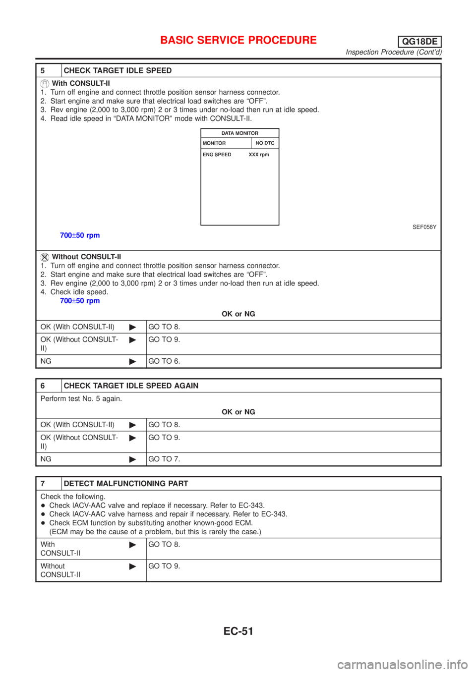
5 CHECK TARGET IDLE SPEED
With CONSULT-II
1. Turn off engine and connect throttle position sensor harness connector.
2. Start engine and make sure that electrical load switches are ªOFFº.
3. Rev engine (2,000 to 3,000 rpm) 2 or 3 times under no-load then run at idle speed.
4. Read idle speed in ªDATA MONITORº mode with CONSULT-II.
SEF058Y
700±50 rpm
Without CONSULT-II
1. Turn off engine and connect throttle position sensor harness connector.
2. Start engine and make sure that electrical load switches are ªOFFº.
3. Rev engine (2,000 to 3,000 rpm) 2 or 3 times under no-load then run at idle speed.
4. Check idle speed.
700±50 rpm
OK or NG
OK (With CONSULT-II)©GO TO 8.
OK (Without CONSULT-
II)©GO TO 9.
NG©GO TO 6.
6 CHECK TARGET IDLE SPEED AGAIN
Perform test No. 5 again.
OK or NG
OK (With CONSULT-II)©GO TO 8.
OK (Without CONSULT-
II)©GO TO 9.
NG©GO TO 7.
7 DETECT MALFUNCTIONING PART
Check the following.
+Check IACV-AAC valve and replace if necessary. Refer to EC-343.
+Check IACV-AAC valve harness and repair if necessary. Refer to EC-343.
+Check ECM function by substituting another known-good ECM.
(ECM may be the cause of a problem, but this is rarely the case.)
With
CONSULT-II©GO TO 8.
Without
CONSULT-II©GO TO 9.
BASIC SERVICE PROCEDUREQG18DE
Inspection Procedure (Cont'd)
EC-51
Page 477 of 3051
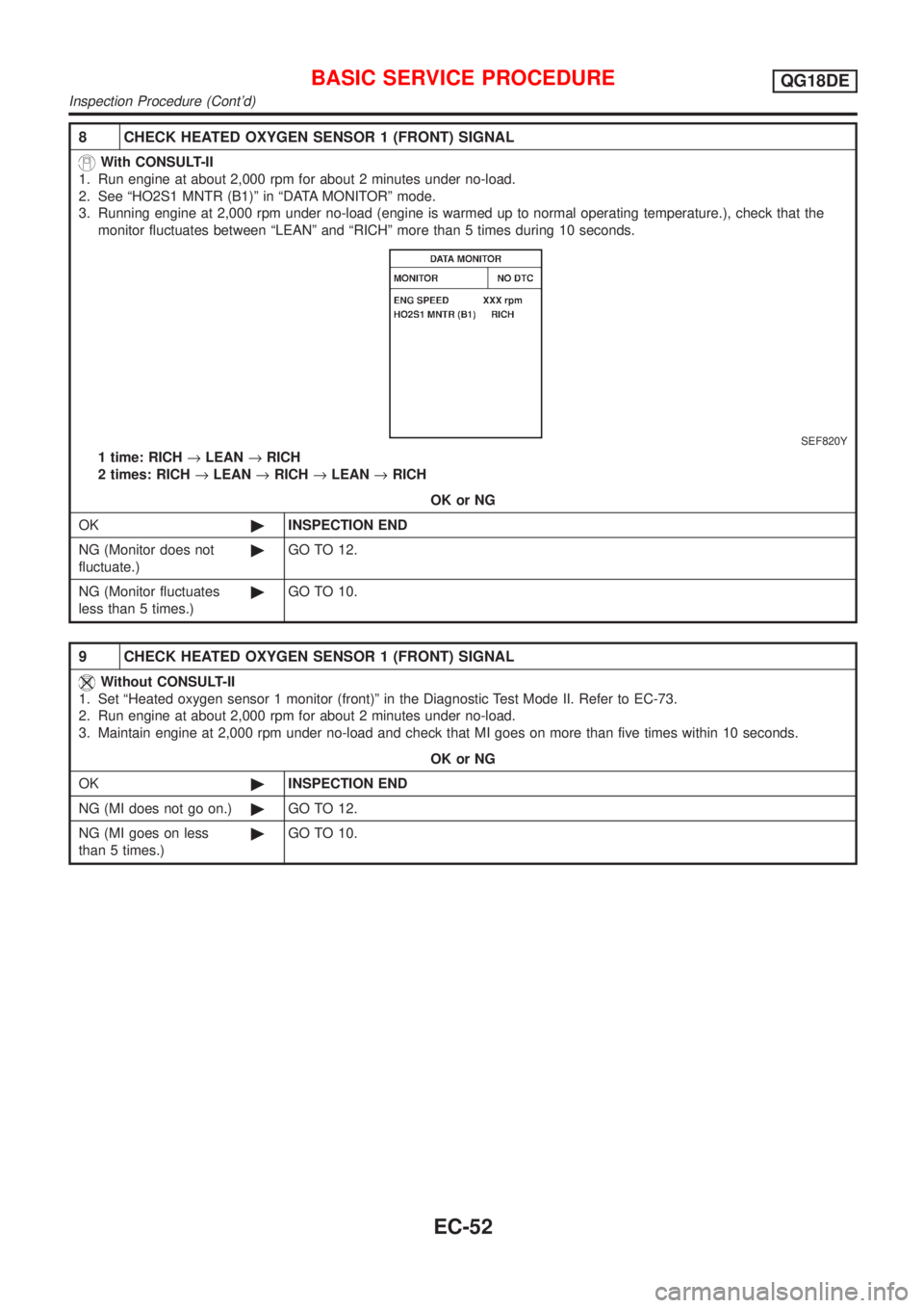
8 CHECK HEATED OXYGEN SENSOR 1 (FRONT) SIGNAL
With CONSULT-II
1. Run engine at about 2,000 rpm for about 2 minutes under no-load.
2. See ªHO2S1 MNTR (B1)º in ªDATA MONITORº mode.
3. Running engine at 2,000 rpm under no-load (engine is warmed up to normal operating temperature.), check that the
monitor fluctuates between ªLEANº and ªRICHº more than 5 times during 10 seconds.
SEF820Y
1 time: RICH®LEAN®RICH
2 times: RICH®LEAN®RICH®LEAN®RICH
OK or NG
OK©INSPECTION END
NG (Monitor does not
fluctuate.)©GO TO 12.
NG (Monitor fluctuates
less than 5 times.)©GO TO 10.
9 CHECK HEATED OXYGEN SENSOR 1 (FRONT) SIGNAL
Without CONSULT-II
1. Set ªHeated oxygen sensor 1 monitor (front)º in the Diagnostic Test Mode II. Refer to EC-73.
2. Run engine at about 2,000 rpm for about 2 minutes under no-load.
3. Maintain engine at 2,000 rpm under no-load and check that MI goes on more than five times within 10 seconds.
OK or NG
OK©INSPECTION END
NG (MI does not go on.)©GO TO 12.
NG (MI goes on less
than 5 times.)©GO TO 10.
BASIC SERVICE PROCEDUREQG18DE
Inspection Procedure (Cont'd)
EC-52
Page 478 of 3051
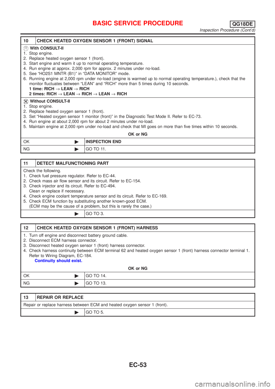
10 CHECK HEATED OXYGEN SENSOR 1 (FRONT) SIGNAL
With CONSULT-II
1. Stop engine.
2. Replace heated oxygen sensor 1 (front).
3. Start engine and warm it up to normal operating temperature.
4. Run engine at approx. 2,000 rpm for approx. 2 minutes under no-load.
5. See ªHO2S1 MNTR (B1)º in ªDATA MONITORº mode.
6. Running engine at 2,000 rpm under no-load (engine is warmed up to normal operating temperature.), check that the
monitor fluctuates between ªLEANº and ªRICHº more than 5 times during 10 seconds.
1 time: RICH®LEAN®RICH
2 times: RICH®LEAN®RICH®LEAN®RICH
Without CONSULT-II
1. Stop engine.
2. Replace heated oxygen sensor 1 (front).
3. Set ªHeated oxygen sensor 1 monitor (front)º in the Diagnostic Test Mode II. Refer to EC-73.
4. Run engine at about 2,000 rpm for about 2 minutes under no-load.
5. Maintain engine at 2,000 rpm under no-load and check that MI goes on more than five times within 10 seconds.
OK or NG
OK©INSPECTION END
NG©GO TO 11.
11 DETECT MALFUNCTIONING PART
Check the following.
1. Check fuel pressure regulator. Refer to EC-44.
2. Check mass air flow sensor and its circuit. Refer to EC-154.
3. Check injector and its circuit. Refer to EC-494.
Clean or replace if necessary.
4. Check engine coolant temperature sensor and its circuit. Refer to EC-169.
5. Check ECM function by substituting another known-good ECM.
(ECM may be the cause of a problem, but this is rarely the case.)
©GO TO 3.
12 CHECK HEATED OXYGEN SENSOR 1 (FRONT) HARNESS
1. Turn off engine and disconnect battery ground cable.
2. Disconnect ECM harness connector.
3. Disconnect heated oxygen sensor 1 (front) harness connector.
4. Check harness continuity between ECM terminal 62 and heated oxygen sensor 1 (front) harness connector terminal 1.
Refer to Wiring Diagram, EC-184.
Continuity should exist.
OK or NG
OK©GO TO 14.
NG©GO TO 13.
13 REPAIR OR REPLACE
Repair or replace harness between ECM and heated oxygen sensor 1 (front).
©GO TO 5.
BASIC SERVICE PROCEDUREQG18DE
Inspection Procedure (Cont'd)
EC-53
Page 479 of 3051
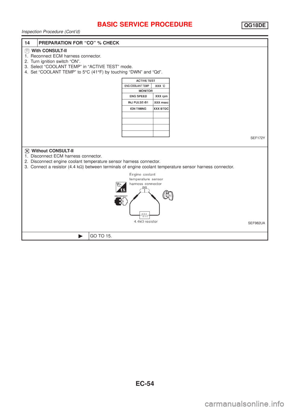
14 PREPARATION FOR ªCOº % CHECK
With CONSULT-II
1. Reconnect ECM harness connector.
2. Turn ignition switch ªONº.
3. Select ªCOOLANT TEMPº in ªACTIVE TESTº mode.
4. Set ªCOOLANT TEMPº to 5ÉC (41ÉF) by touching ªDWNº and ªQdº.
SEF172Y
Without CONSULT-II
1. Disconnect ECM harness connector.
2. Disconnect engine coolant temperature sensor harness connector.
3. Connect a resistor (4.4 kW) between terminals of engine coolant temperature sensor harness connector.
SEF982UA
©GO TO 15.
BASIC SERVICE PROCEDUREQG18DE
Inspection Procedure (Cont'd)
EC-54
Page 480 of 3051
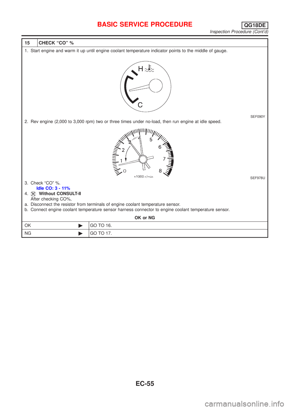
15 CHECK ªCOº %
1. Start engine and warm it up until engine coolant temperature indicator points to the middle of gauge.
SEF090Y
2. Rev engine (2,000 to 3,000 rpm) two or three times under no-load, then run engine at idle speed.
SEF978U
3. Check ªCOº %.
Idle CO:3-11%
4.
Without CONSULT-II
After checking CO%,
a. Disconnect the resistor from terminals of engine coolant temperature sensor.
b. Connect engine coolant temperature sensor harness connector to engine coolant temperature sensor.
OK or NG
OK©GO TO 16.
NG©GO TO 17.
BASIC SERVICE PROCEDUREQG18DE
Inspection Procedure (Cont'd)
EC-55