NISSAN ALMERA TINO 2001 Service Repair Manual
Manufacturer: NISSAN, Model Year: 2001, Model line: ALMERA TINO, Model: NISSAN ALMERA TINO 2001Pages: 3051, PDF Size: 46.38 MB
Page 431 of 3051
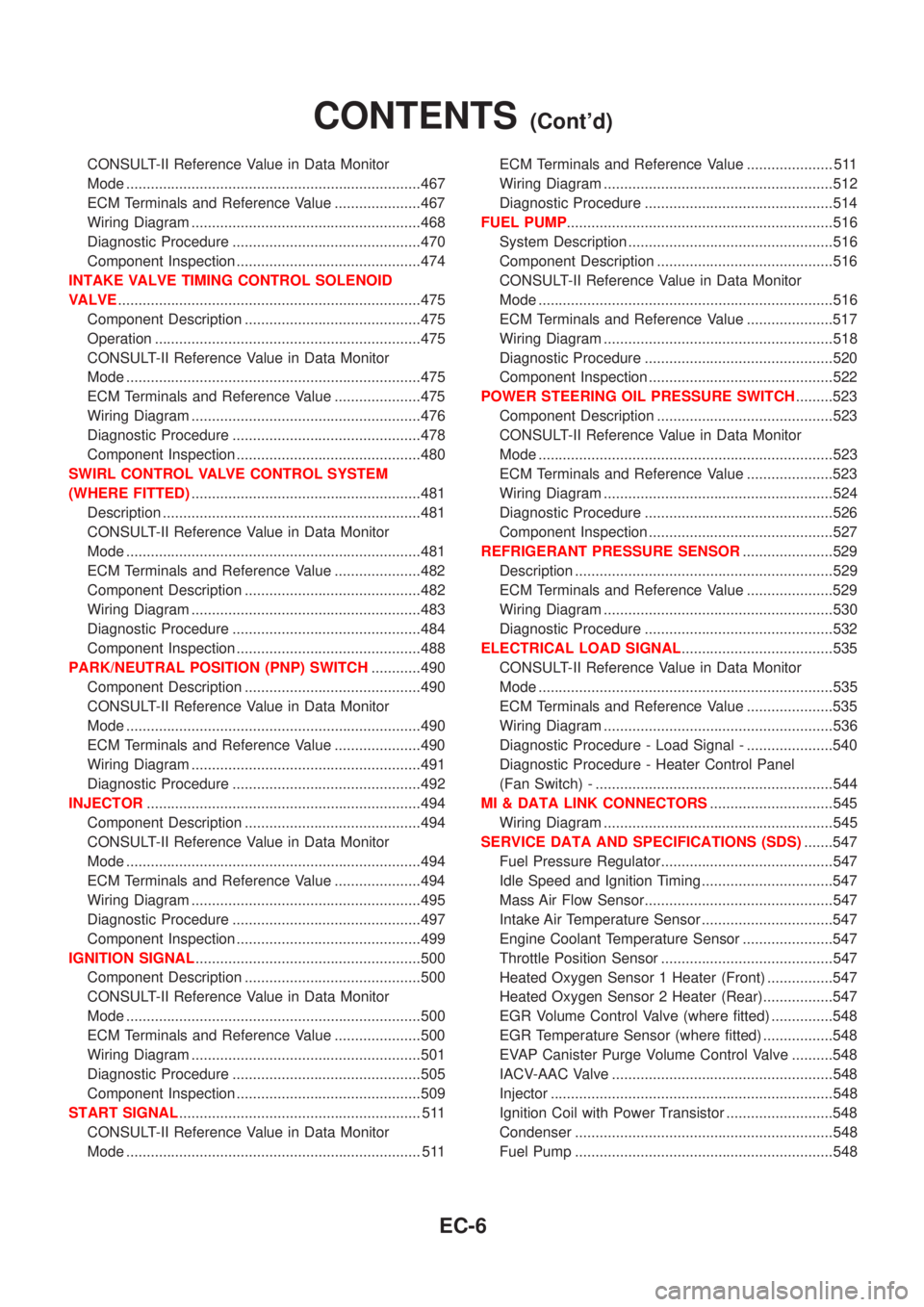
CONSULT-II Reference Value in Data Monitor
Mode ........................................................................467
ECM Terminals and Reference Value .....................467
Wiring Diagram ........................................................468
Diagnostic Procedure ..............................................470
Component Inspection .............................................474
INTAKE VALVE TIMING CONTROL SOLENOID
VALVE..........................................................................475
Component Description ...........................................475
Operation .................................................................475
CONSULT-II Reference Value in Data Monitor
Mode ........................................................................475
ECM Terminals and Reference Value .....................475
Wiring Diagram ........................................................476
Diagnostic Procedure ..............................................478
Component Inspection .............................................480
SWIRL CONTROL VALVE CONTROL SYSTEM
(WHERE FITTED)........................................................481
Description ...............................................................481
CONSULT-II Reference Value in Data Monitor
Mode ........................................................................481
ECM Terminals and Reference Value .....................482
Component Description ...........................................482
Wiring Diagram ........................................................483
Diagnostic Procedure ..............................................484
Component Inspection .............................................488
PARK/NEUTRAL POSITION (PNP) SWITCH............490
Component Description ...........................................490
CONSULT-II Reference Value in Data Monitor
Mode ........................................................................490
ECM Terminals and Reference Value .....................490
Wiring Diagram ........................................................491
Diagnostic Procedure ..............................................492
INJECTOR...................................................................494
Component Description ...........................................494
CONSULT-II Reference Value in Data Monitor
Mode ........................................................................494
ECM Terminals and Reference Value .....................494
Wiring Diagram ........................................................495
Diagnostic Procedure ..............................................497
Component Inspection .............................................499
IGNITION SIGNAL.......................................................500
Component Description ...........................................500
CONSULT-II Reference Value in Data Monitor
Mode ........................................................................500
ECM Terminals and Reference Value .....................500
Wiring Diagram ........................................................501
Diagnostic Procedure ..............................................505
Component Inspection .............................................509
START SIGNAL........................................................... 511
CONSULT-II Reference Value in Data Monitor
Mode ........................................................................ 511ECM Terminals and Reference Value ..................... 511
Wiring Diagram ........................................................512
Diagnostic Procedure ..............................................514
FUEL PUMP.................................................................516
System Description ..................................................516
Component Description ...........................................516
CONSULT-II Reference Value in Data Monitor
Mode ........................................................................516
ECM Terminals and Reference Value .....................517
Wiring Diagram ........................................................518
Diagnostic Procedure ..............................................520
Component Inspection .............................................522
POWER STEERING OIL PRESSURE SWITCH.........523
Component Description ...........................................523
CONSULT-II Reference Value in Data Monitor
Mode ........................................................................523
ECM Terminals and Reference Value .....................523
Wiring Diagram ........................................................524
Diagnostic Procedure ..............................................526
Component Inspection .............................................527
REFRIGERANT PRESSURE SENSOR......................529
Description ...............................................................529
ECM Terminals and Reference Value .....................529
Wiring Diagram ........................................................530
Diagnostic Procedure ..............................................532
ELECTRICAL LOAD SIGNAL.....................................535
CONSULT-II Reference Value in Data Monitor
Mode ........................................................................535
ECM Terminals and Reference Value .....................535
Wiring Diagram ........................................................536
Diagnostic Procedure - Load Signal - .....................540
Diagnostic Procedure - Heater Control Panel
(Fan Switch) - ..........................................................544
MI & DATA LINK CONNECTORS..............................545
Wiring Diagram ........................................................545
SERVICE DATA AND SPECIFICATIONS (SDS).......547
Fuel Pressure Regulator..........................................547
Idle Speed and Ignition Timing ................................547
Mass Air Flow Sensor..............................................547
Intake Air Temperature Sensor ................................547
Engine Coolant Temperature Sensor ......................547
Throttle Position Sensor ..........................................547
Heated Oxygen Sensor 1 Heater (Front) ................547
Heated Oxygen Sensor 2 Heater (Rear).................547
EGR Volume Control Valve (where fitted) ...............548
EGR Temperature Sensor (where fitted) .................548
EVAP Canister Purge Volume Control Valve ..........548
IACV-AAC Valve ......................................................548
Injector .....................................................................548
Ignition Coil with Power Transistor ..........................548
Condenser ...............................................................548
Fuel Pump ...............................................................548
CONTENTS(Cont'd)
EC-6
Page 432 of 3051
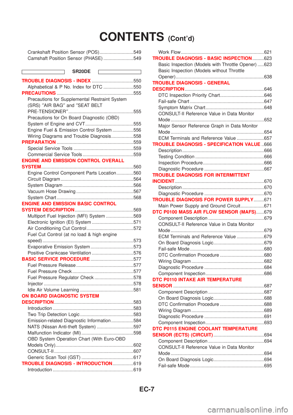
Crankshaft Position Sensor (POS) ..........................549
Camshaft Position Sensor (PHASE) .......................549
SR20DE
TROUBLE DIAGNOSIS - INDEX................................550
Alphabetical & P No. Index for DTC .......................550
PRECAUTIONS...........................................................555
Precautions for Supplemental Restraint System
(SRS)²AIR BAG²and²SEAT BELT
PRE-TENSIONER²..................................................555
Precautions for On Board Diagnostic (OBD)
System of Engine and CVT .....................................555
Engine Fuel & Emission Control System ................556
Wiring Diagrams and Trouble Diagnosis .................558
PREPARATION...........................................................559
Special Service Tools ..............................................559
Commercial Service Tools .......................................559
ENGINE AND EMISSION CONTROL OVERALL
SYSTEM.......................................................................560
Engine Control Component Parts Location .............560
Circuit Diagram ........................................................564
System Diagram ......................................................566
Vacuum Hose Drawing ............................................567
System Chart ...........................................................568
ENGINE AND EMISSION BASIC CONTROL
SYSTEM DESCRIPTION.............................................569
Multiport Fuel Injection (MFI) System .....................569
Electronic Ignition (EI) System ................................571
Air Conditioning Cut Control ....................................572
Fuel Cut Control (at no load & high engine
speed) ......................................................................573
Evaporative Emission System .................................573
Positive Crankcase Ventilation ................................576
BASIC SERVICE PROCEDURE.................................577
Fuel Pressure Release ............................................577
Fuel Pressure Check ...............................................577
Fuel Pressure Regulator Check ..............................578
Injector .....................................................................578
Idle Air Volume Learning .........................................581
ON BOARD DIAGNOSTIC SYSTEM
DESCRIPTION.............................................................583
Introduction ..............................................................583
Two Trip Detection Logic .........................................583
Emission-related Diagnostic Information .................584
NATS (Nissan Anti-theft System) ............................597
Malfunction Indicator (MI) ........................................598
OBD System Operation Chart (With Euro-OBD
Models Only)............................................................602
CONSULT-II .............................................................607
Generic Scan Tool (GST) ........................................617
TROUBLE DIAGNOSIS - INTRODUCTION................619
Introduction ..............................................................619Work Flow ................................................................621
TROUBLE DIAGNOSIS - BASIC INSPECTION.........623
Basic Inspection (Models with Throttle Opener) .....623
Basic Inspection (Models without Throttle
Opener) ....................................................................638
TROUBLE DIAGNOSIS - GENERAL
DESCRIPTION.............................................................646
DTC Inspection Priority Chart..................................646
Fail-safe Chart .........................................................647
Symptom Matrix Chart .............................................648
CONSULT-II Reference Value in Data Monitor
Mode ........................................................................652
Major Sensor Reference Graph in Data Monitor
Mode ........................................................................654
ECM Terminals and Reference Value .....................657
TROUBLE DIAGNOSIS - SPECIFICATION VALUE..666
Description ...............................................................666
Testing Condition .....................................................666
Inspection Procedure ...............................................666
Diagnostic Procedure ..............................................667
TROUBLE DIAGNOSIS FOR INTERMITTENT
INCIDENT.....................................................................670
Description ...............................................................670
Diagnostic Procedure ..............................................670
TROUBLE DIAGNOSIS FOR POWER SUPPLY........671
Main Power Supply and Ground Circuit ..................671
DTC P0100 MASS AIR FLOW SENSOR (MAFS)......679
Component Description ...........................................679
CONSULT-II Reference Value in Data Monitor
Mode ........................................................................679
ECM Terminals and Reference Value .....................679
On Board Diagnosis Logic.......................................679
Fail-safe Mode .........................................................680
DTC Confirmation Procedure ..................................680
Wiring Diagram ........................................................682
Diagnostic Procedure ..............................................684
Component Inspection .............................................686
DTC P0110 INTAKE AIR TEMPERATURE
SENSOR......................................................................687
Component Description ...........................................687
On Board Diagnosis Logic.......................................688
DTC Confirmation Procedure ..................................688
Wiring Diagram ........................................................689
Diagnostic Procedure ..............................................691
Component Inspection .............................................693
DTC P0115 ENGINE COOLANT TEMPERATURE
SENSOR (ECTS) (CIRCUIT).......................................694
Component Description ...........................................694
CONSULT-II Reference Value in Data Monitor
Mode ........................................................................694
On Board Diagnosis Logic.......................................694
Fail-safe Mode .........................................................695
CONTENTS(Cont'd)
EC-7
Page 433 of 3051
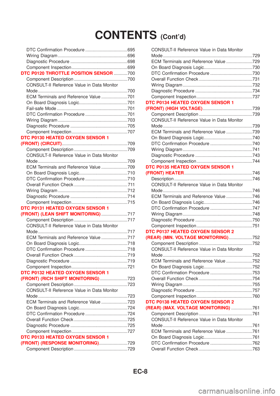
DTC Confirmation Procedure ..................................695
Wiring Diagram ........................................................696
Diagnostic Procedure ..............................................698
Component Inspection .............................................699
DTC P0120 THROTTLE POSITION SENSOR...........700
Component Description ...........................................700
CONSULT-II Reference Value in Data Monitor
Mode ........................................................................700
ECM Terminals and Reference Value .....................701
On Board Diagnosis Logic.......................................701
Fail-safe Mode .........................................................701
DTC Confirmation Procedure ..................................701
Wiring Diagram ........................................................703
Diagnostic Procedure ..............................................705
Component Inspection .............................................707
DTC P0130 HEATED OXYGEN SENSOR 1
(FRONT) (CIRCUIT).....................................................709
Component Description ...........................................709
CONSULT-II Reference Value in Data Monitor
Mode ........................................................................709
ECM Terminals and Reference Value .....................709
On Board Diagnosis Logic.......................................710
DTC Confirmation Procedure ..................................710
Overall Function Check ........................................... 711
Wiring Diagram ........................................................712
Diagnostic Procedure ..............................................714
Component Inspection .............................................715
DTC P0131 HEATED OXYGEN SENSOR 1
(FRONT) (LEAN SHIFT MONITORING).....................717
Component Description ...........................................717
CONSULT-II Reference Value in Data Monitor
Mode ........................................................................717
ECM Terminals and Reference Value .....................717
On Board Diagnosis Logic.......................................718
DTC Confirmation Procedure ..................................718
Overall Function Check ...........................................719
Diagnostic Procedure ..............................................719
Component Inspection .............................................721
DTC P0132 HEATED OXYGEN SENSOR 1
(FRONT) (RICH SHIFT MONITORING)......................723
Component Description ...........................................723
CONSULT-II Reference Value in Data Monitor
Mode ........................................................................723
ECM Terminals and Reference Value .....................723
On Board Diagnosis Logic.......................................724
DTC Confirmation Procedure ..................................724
Overall Function Check ...........................................725
Diagnostic Procedure ..............................................725
Component Inspection .............................................727
DTC P0133 HEATED OXYGEN SENSOR 1
(FRONT) (RESPONSE MONITORING).......................729
Component Description ...........................................729CONSULT-II Reference Value in Data Monitor
Mode ........................................................................729
ECM Terminals and Reference Value .....................729
On Board Diagnosis Logic.......................................730
DTC Confirmation Procedure ..................................730
Overall Function Check ...........................................731
Wiring Diagram ........................................................732
Diagnostic Procedure ..............................................734
Component Inspection .............................................737
DTC P0134 HEATED OXYGEN SENSOR 1
(FRONT) (HIGH VOLTAGE)........................................739
Component Description ...........................................739
CONSULT-II Reference Value in Data Monitor
Mode ........................................................................739
ECM Terminals and Reference Value .....................739
On Board Diagnosis Logic.......................................740
DTC Confirmation Procedure ..................................740
Wiring Diagram ........................................................741
Diagnostic Procedure ..............................................743
Component Inspection .............................................744
DTC P0135 HEATED OXYGEN SENSOR 1
(FRONT) HEATER.......................................................746
Description ...............................................................746
CONSULT-II Reference Value in Data Monitor
Mode ........................................................................746
ECM Terminals and Reference Value .....................746
On Board Diagnosis Logic.......................................746
DTC Confirmation Procedure ..................................747
Wiring Diagram ........................................................748
Diagnostic Procedure ..............................................750
Component Inspection .............................................751
DTC P0137 HEATED OXYGEN SENSOR 2
(REAR) (MIN. VOLTAGE MONITORING)...................752
Component Description ...........................................752
CONSULT-II Reference Value in Data Monitor
Mode ........................................................................752
ECM Terminals and Reference Value .....................752
On Board Diagnosis Logic.......................................752
DTC Confirmation Procedure ..................................753
Overall Function Check ...........................................754
Wiring Diagram ........................................................755
Diagnostic Procedure ..............................................757
Component Inspection .............................................760
DTC P0138 HEATED OXYGEN SENSOR 2
(REAR) (MAX. VOLTAGE MONITORING).................761
Component Description ...........................................761
CONSULT-II Reference Value in Data Monitor
Mode ........................................................................761
ECM Terminals and Reference Value .....................761
On Board Diagnosis Logic.......................................761
DTC Confirmation Procedure ..................................762
Overall Function Check ...........................................763
CONTENTS(Cont'd)
EC-8
Page 434 of 3051
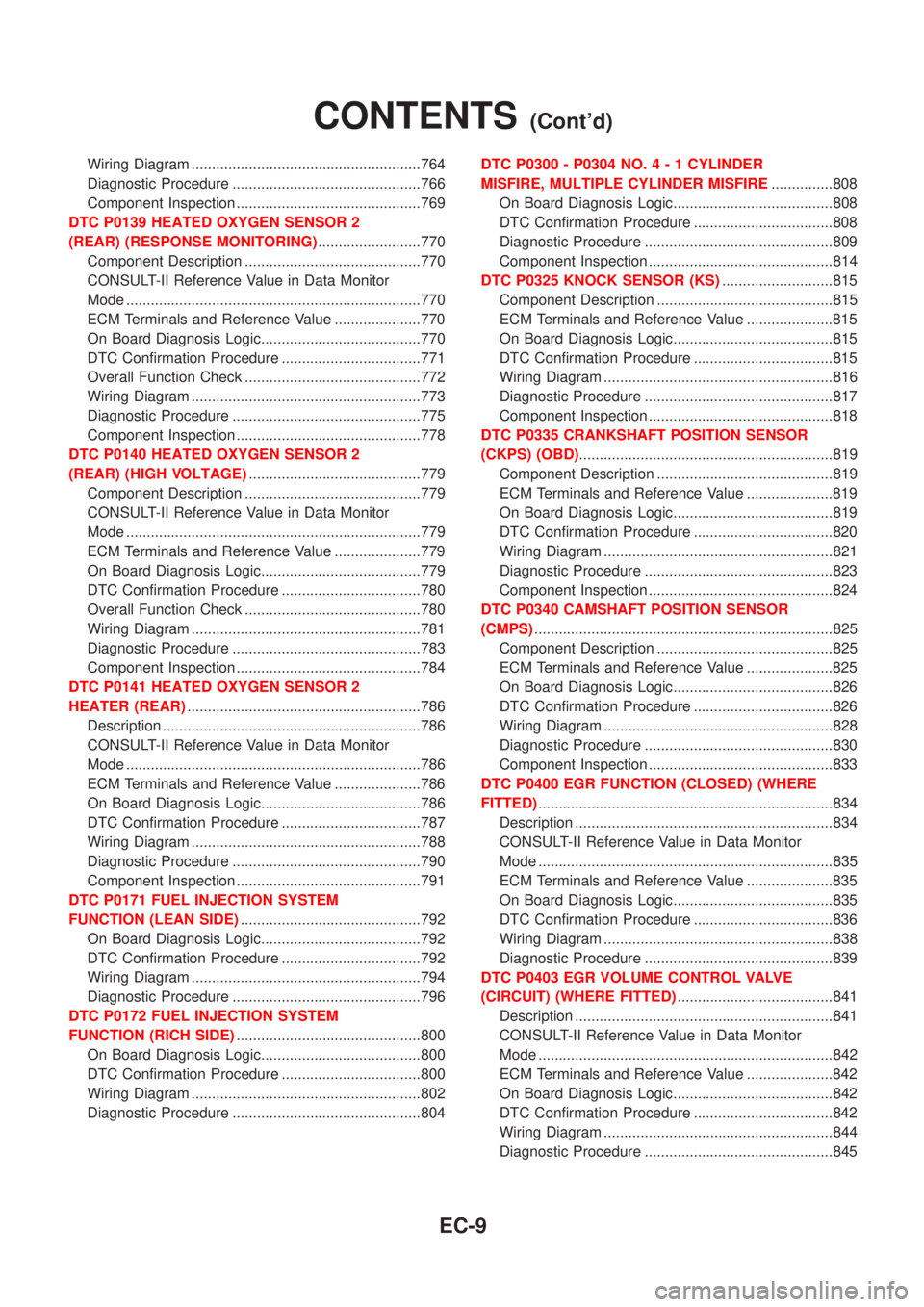
Wiring Diagram ........................................................764
Diagnostic Procedure ..............................................766
Component Inspection .............................................769
DTC P0139 HEATED OXYGEN SENSOR 2
(REAR) (RESPONSE MONITORING).........................770
Component Description ...........................................770
CONSULT-II Reference Value in Data Monitor
Mode ........................................................................770
ECM Terminals and Reference Value .....................770
On Board Diagnosis Logic.......................................770
DTC Confirmation Procedure ..................................771
Overall Function Check ...........................................772
Wiring Diagram ........................................................773
Diagnostic Procedure ..............................................775
Component Inspection .............................................778
DTC P0140 HEATED OXYGEN SENSOR 2
(REAR) (HIGH VOLTAGE)..........................................779
Component Description ...........................................779
CONSULT-II Reference Value in Data Monitor
Mode ........................................................................779
ECM Terminals and Reference Value .....................779
On Board Diagnosis Logic.......................................779
DTC Confirmation Procedure ..................................780
Overall Function Check ...........................................780
Wiring Diagram ........................................................781
Diagnostic Procedure ..............................................783
Component Inspection .............................................784
DTC P0141 HEATED OXYGEN SENSOR 2
HEATER (REAR).........................................................786
Description ...............................................................786
CONSULT-II Reference Value in Data Monitor
Mode ........................................................................786
ECM Terminals and Reference Value .....................786
On Board Diagnosis Logic.......................................786
DTC Confirmation Procedure ..................................787
Wiring Diagram ........................................................788
Diagnostic Procedure ..............................................790
Component Inspection .............................................791
DTC P0171 FUEL INJECTION SYSTEM
FUNCTION (LEAN SIDE)............................................792
On Board Diagnosis Logic.......................................792
DTC Confirmation Procedure ..................................792
Wiring Diagram ........................................................794
Diagnostic Procedure ..............................................796
DTC P0172 FUEL INJECTION SYSTEM
FUNCTION (RICH SIDE).............................................800
On Board Diagnosis Logic.......................................800
DTC Confirmation Procedure ..................................800
Wiring Diagram ........................................................802
Diagnostic Procedure ..............................................804DTC P0300 - P0304 NO.4-1CYLINDER
MISFIRE, MULTIPLE CYLINDER MISFIRE...............808
On Board Diagnosis Logic.......................................808
DTC Confirmation Procedure ..................................808
Diagnostic Procedure ..............................................809
Component Inspection .............................................814
DTC P0325 KNOCK SENSOR (KS)...........................815
Component Description ...........................................815
ECM Terminals and Reference Value .....................815
On Board Diagnosis Logic.......................................815
DTC Confirmation Procedure ..................................815
Wiring Diagram ........................................................816
Diagnostic Procedure ..............................................817
Component Inspection .............................................818
DTC P0335 CRANKSHAFT POSITION SENSOR
(CKPS) (OBD)..............................................................819
Component Description ...........................................819
ECM Terminals and Reference Value .....................819
On Board Diagnosis Logic.......................................819
DTC Confirmation Procedure ..................................820
Wiring Diagram ........................................................821
Diagnostic Procedure ..............................................823
Component Inspection .............................................824
DTC P0340 CAMSHAFT POSITION SENSOR
(CMPS).........................................................................825
Component Description ...........................................825
ECM Terminals and Reference Value .....................825
On Board Diagnosis Logic.......................................826
DTC Confirmation Procedure ..................................826
Wiring Diagram ........................................................828
Diagnostic Procedure ..............................................830
Component Inspection .............................................833
DTC P0400 EGR FUNCTION (CLOSED) (WHERE
FITTED)........................................................................834
Description ...............................................................834
CONSULT-II Reference Value in Data Monitor
Mode ........................................................................835
ECM Terminals and Reference Value .....................835
On Board Diagnosis Logic.......................................835
DTC Confirmation Procedure ..................................836
Wiring Diagram ........................................................838
Diagnostic Procedure ..............................................839
DTC P0403 EGR VOLUME CONTROL VALVE
(CIRCUIT) (WHERE FITTED)......................................841
Description ...............................................................841
CONSULT-II Reference Value in Data Monitor
Mode ........................................................................842
ECM Terminals and Reference Value .....................842
On Board Diagnosis Logic.......................................842
DTC Confirmation Procedure ..................................842
Wiring Diagram ........................................................844
Diagnostic Procedure ..............................................845
CONTENTS(Cont'd)
EC-9
Page 435 of 3051
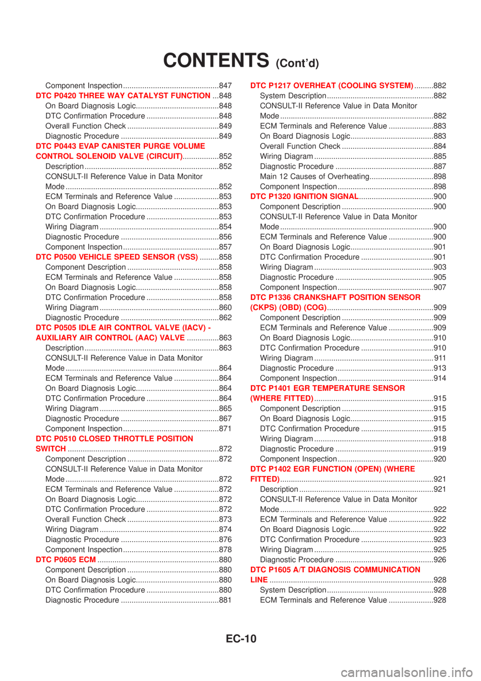
Component Inspection .............................................847
DTC P0420 THREE WAY CATALYST FUNCTION...848
On Board Diagnosis Logic.......................................848
DTC Confirmation Procedure ..................................848
Overall Function Check ...........................................849
Diagnostic Procedure ..............................................849
DTC P0443 EVAP CANISTER PURGE VOLUME
CONTROL SOLENOID VALVE (CIRCUIT).................852
Description ...............................................................852
CONSULT-II Reference Value in Data Monitor
Mode ........................................................................852
ECM Terminals and Reference Value .....................853
On Board Diagnosis Logic.......................................853
DTC Confirmation Procedure ..................................853
Wiring Diagram ........................................................854
Diagnostic Procedure ..............................................856
Component Inspection .............................................857
DTC P0500 VEHICLE SPEED SENSOR (VSS).........858
Component Description ...........................................858
ECM Terminals and Reference Value .....................858
On Board Diagnosis Logic.......................................858
DTC Confirmation Procedure ..................................858
Wiring Diagram ........................................................860
Diagnostic Procedure ..............................................862
DTC P0505 IDLE AIR CONTROL VALVE (IACV) -
AUXILIARY AIR CONTROL (AAC) VALVE...............863
Description ...............................................................863
CONSULT-II Reference Value in Data Monitor
Mode ........................................................................864
ECM Terminals and Reference Value .....................864
On Board Diagnosis Logic.......................................864
DTC Confirmation Procedure ..................................864
Wiring Diagram ........................................................865
Diagnostic Procedure ..............................................867
Component Inspection .............................................871
DTC P0510 CLOSED THROTTLE POSITION
SWITCH.......................................................................872
Component Description ...........................................872
CONSULT-II Reference Value in Data Monitor
Mode ........................................................................872
ECM Terminals and Reference Value .....................872
On Board Diagnosis Logic.......................................872
DTC Confirmation Procedure ..................................872
Overall Function Check ...........................................873
Wiring Diagram ........................................................874
Diagnostic Procedure ..............................................876
Component Inspection .............................................878
DTC P0605 ECM.........................................................880
Component Description ...........................................880
On Board Diagnosis Logic.......................................880
DTC Confirmation Procedure ..................................880
Diagnostic Procedure ..............................................881DTC P1217 OVERHEAT (COOLING SYSTEM).........882
System Description ..................................................882
CONSULT-II Reference Value in Data Monitor
Mode ........................................................................882
ECM Terminals and Reference Value .....................883
On Board Diagnosis Logic.......................................883
Overall Function Check ...........................................884
Wiring Diagram ........................................................885
Diagnostic Procedure ..............................................887
Main 12 Causes of Overheating..............................898
Component Inspection .............................................898
DTC P1320 IGNITION SIGNAL...................................900
Component Description ...........................................900
CONSULT-II Reference Value in Data Monitor
Mode ........................................................................900
ECM Terminals and Reference Value .....................900
On Board Diagnosis Logic.......................................901
DTC Confirmation Procedure ..................................901
Wiring Diagram ........................................................903
Diagnostic Procedure ..............................................905
Component Inspection .............................................907
DTC P1336 CRANKSHAFT POSITION SENSOR
(CKPS) (OBD) (COG)..................................................909
Component Description ...........................................909
ECM Terminals and Reference Value .....................909
On Board Diagnosis Logic.......................................910
DTC Confirmation Procedure ..................................910
Wiring Diagram ........................................................ 911
Diagnostic Procedure ..............................................913
Component Inspection .............................................914
DTC P1401 EGR TEMPERATURE SENSOR
(WHERE FITTED)........................................................915
Component Description ...........................................915
On Board Diagnosis Logic.......................................915
DTC Confirmation Procedure ..................................915
Wiring Diagram ........................................................918
Diagnostic Procedure ..............................................919
Component Inspection .............................................920
DTC P1402 EGR FUNCTION (OPEN) (WHERE
FITTED)........................................................................921
Description ...............................................................921
CONSULT-II Reference Value in Data Monitor
Mode ........................................................................922
ECM Terminals and Reference Value .....................922
On Board Diagnosis Logic.......................................922
DTC Confirmation Procedure ..................................923
Wiring Diagram ........................................................925
Diagnostic Procedure ..............................................926
DTC P1605 A/T DIAGNOSIS COMMUNICATION
LINE.............................................................................928
System Description ..................................................928
ECM Terminals and Reference Value .....................928
CONTENTS(Cont'd)
EC-10
Page 436 of 3051
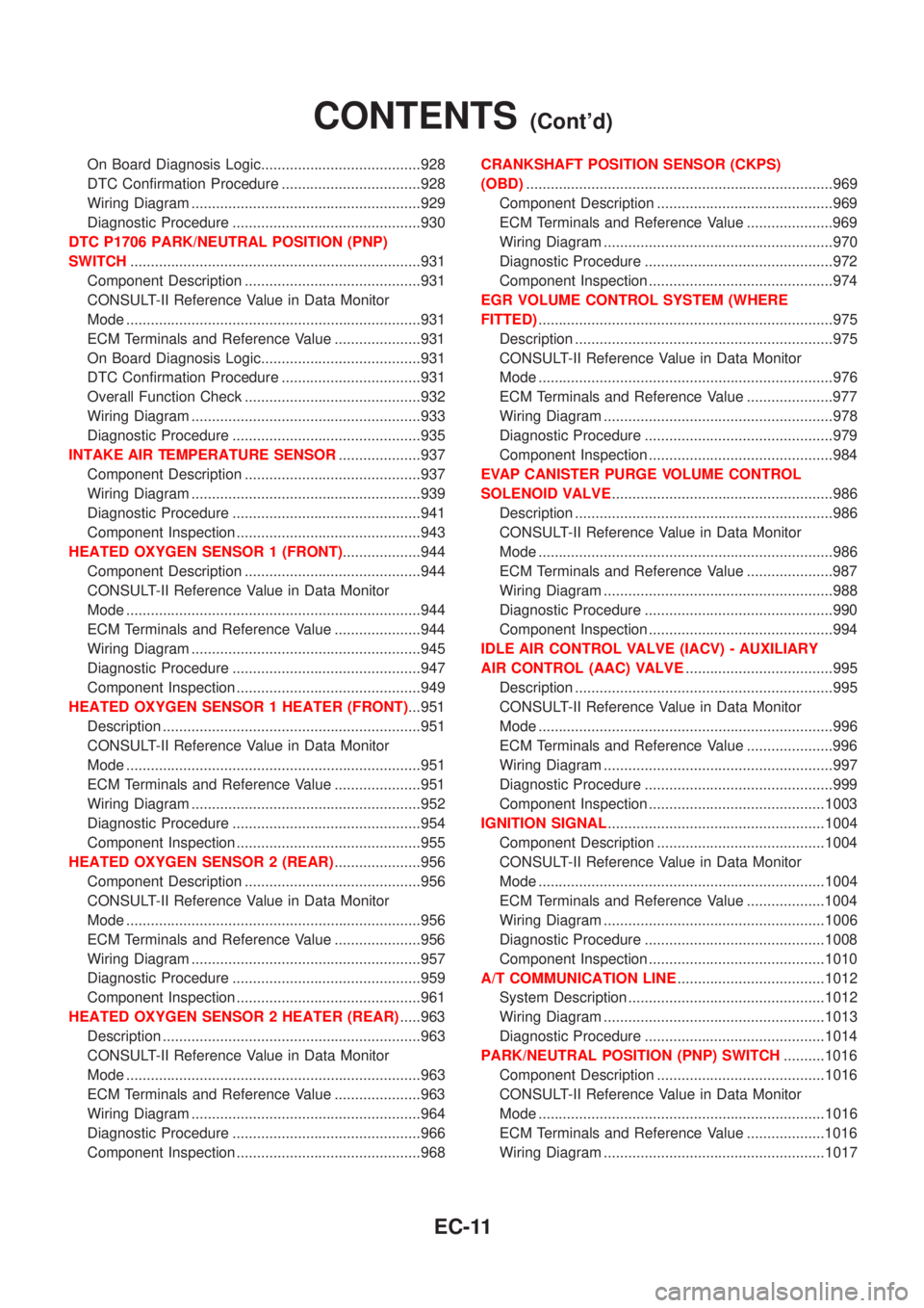
On Board Diagnosis Logic.......................................928
DTC Confirmation Procedure ..................................928
Wiring Diagram ........................................................929
Diagnostic Procedure ..............................................930
DTC P1706 PARK/NEUTRAL POSITION (PNP)
SWITCH.......................................................................931
Component Description ...........................................931
CONSULT-II Reference Value in Data Monitor
Mode ........................................................................931
ECM Terminals and Reference Value .....................931
On Board Diagnosis Logic.......................................931
DTC Confirmation Procedure ..................................931
Overall Function Check ...........................................932
Wiring Diagram ........................................................933
Diagnostic Procedure ..............................................935
INTAKE AIR TEMPERATURE SENSOR....................937
Component Description ...........................................937
Wiring Diagram ........................................................939
Diagnostic Procedure ..............................................941
Component Inspection .............................................943
HEATED OXYGEN SENSOR 1 (FRONT)...................944
Component Description ...........................................944
CONSULT-II Reference Value in Data Monitor
Mode ........................................................................944
ECM Terminals and Reference Value .....................944
Wiring Diagram ........................................................945
Diagnostic Procedure ..............................................947
Component Inspection .............................................949
HEATED OXYGEN SENSOR 1 HEATER (FRONT)...951
Description ...............................................................951
CONSULT-II Reference Value in Data Monitor
Mode ........................................................................951
ECM Terminals and Reference Value .....................951
Wiring Diagram ........................................................952
Diagnostic Procedure ..............................................954
Component Inspection .............................................955
HEATED OXYGEN SENSOR 2 (REAR).....................956
Component Description ...........................................956
CONSULT-II Reference Value in Data Monitor
Mode ........................................................................956
ECM Terminals and Reference Value .....................956
Wiring Diagram ........................................................957
Diagnostic Procedure ..............................................959
Component Inspection .............................................961
HEATED OXYGEN SENSOR 2 HEATER (REAR).....963
Description ...............................................................963
CONSULT-II Reference Value in Data Monitor
Mode ........................................................................963
ECM Terminals and Reference Value .....................963
Wiring Diagram ........................................................964
Diagnostic Procedure ..............................................966
Component Inspection .............................................968CRANKSHAFT POSITION SENSOR (CKPS)
(OBD)...........................................................................969
Component Description ...........................................969
ECM Terminals and Reference Value .....................969
Wiring Diagram ........................................................970
Diagnostic Procedure ..............................................972
Component Inspection .............................................974
EGR VOLUME CONTROL SYSTEM (WHERE
FITTED)........................................................................975
Description ...............................................................975
CONSULT-II Reference Value in Data Monitor
Mode ........................................................................976
ECM Terminals and Reference Value .....................977
Wiring Diagram ........................................................978
Diagnostic Procedure ..............................................979
Component Inspection .............................................984
EVAP CANISTER PURGE VOLUME CONTROL
SOLENOID VALVE......................................................986
Description ...............................................................986
CONSULT-II Reference Value in Data Monitor
Mode ........................................................................986
ECM Terminals and Reference Value .....................987
Wiring Diagram ........................................................988
Diagnostic Procedure ..............................................990
Component Inspection .............................................994
IDLE AIR CONTROL VALVE (IACV) - AUXILIARY
AIR CONTROL (AAC) VALVE....................................995
Description ...............................................................995
CONSULT-II Reference Value in Data Monitor
Mode ........................................................................996
ECM Terminals and Reference Value .....................996
Wiring Diagram ........................................................997
Diagnostic Procedure ..............................................999
Component Inspection ...........................................1003
IGNITION SIGNAL.....................................................1004
Component Description .........................................1004
CONSULT-II Reference Value in Data Monitor
Mode ......................................................................1004
ECM Terminals and Reference Value ...................1004
Wiring Diagram ......................................................1006
Diagnostic Procedure ............................................1008
Component Inspection ...........................................1010
A/T COMMUNICATION LINE....................................1012
System Description ................................................1012
Wiring Diagram ......................................................1013
Diagnostic Procedure ............................................1014
PARK/NEUTRAL POSITION (PNP) SWITCH..........1016
Component Description .........................................1016
CONSULT-II Reference Value in Data Monitor
Mode ......................................................................1016
ECM Terminals and Reference Value ...................1016
Wiring Diagram ......................................................1017
CONTENTS(Cont'd)
EC-11
Page 437 of 3051
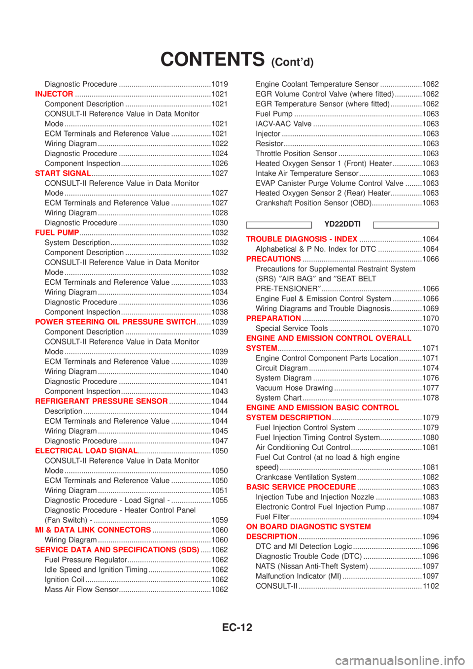
Diagnostic Procedure ............................................1019
INJECTOR.................................................................1021
Component Description .........................................1021
CONSULT-II Reference Value in Data Monitor
Mode ......................................................................1021
ECM Terminals and Reference Value ...................1021
Wiring Diagram ......................................................1022
Diagnostic Procedure ............................................1024
Component Inspection ...........................................1026
START SIGNAL.........................................................1027
CONSULT-II Reference Value in Data Monitor
Mode ......................................................................1027
ECM Terminals and Reference Value ...................1027
Wiring Diagram ......................................................1028
Diagnostic Procedure ............................................1030
FUEL PUMP...............................................................1032
System Description ................................................1032
Component Description .........................................1032
CONSULT-II Reference Value in Data Monitor
Mode ......................................................................1032
ECM Terminals and Reference Value ...................1033
Wiring Diagram ......................................................1034
Diagnostic Procedure ............................................1036
Component Inspection ...........................................1038
POWER STEERING OIL PRESSURE SWITCH.......1039
Component Description .........................................1039
CONSULT-II Reference Value in Data Monitor
Mode ......................................................................1039
ECM Terminals and Reference Value ...................1039
Wiring Diagram ......................................................1040
Diagnostic Procedure ............................................1041
Component Inspection ...........................................1043
REFRIGERANT PRESSURE SENSOR....................1044
Description .............................................................1044
ECM Terminals and Reference Value ...................1044
Wiring Diagram ......................................................1045
Diagnostic Procedure ............................................1047
ELECTRICAL LOAD SIGNAL...................................1050
CONSULT-II Reference Value in Data Monitor
Mode ......................................................................1050
ECM Terminals and Reference Value ...................1050
Wiring Diagram ......................................................1051
Diagnostic Procedure - Load Signal - ...................1055
Diagnostic Procedure - Heater Control Panel
(Fan Switch) - ........................................................1059
MI & DATA LINK CONNECTORS............................1060
Wiring Diagram ......................................................1060
SERVICE DATA AND SPECIFICATIONS (SDS).....1062
Fuel Pressure Regulator........................................1062
Idle Speed and Ignition Timing ..............................1062
Ignition Coil ............................................................1062
Mass Air Flow Sensor............................................1062Engine Coolant Temperature Sensor ....................1062
EGR Volume Control Valve (where fitted) .............1062
EGR Temperature Sensor (where fitted) ...............1062
Fuel Pump .............................................................1063
IACV-AAC Valve ....................................................1063
Injector ...................................................................1063
Resistor ..................................................................1063
Throttle Position Sensor ........................................1063
Heated Oxygen Sensor 1 (Front) Heater ..............1063
Intake Air Temperature Sensor ..............................1063
EVAP Canister Purge Volume Control Valve ........1063
Heated Oxygen Sensor 2 (Rear) Heater...............1063
Crankshaft Position Sensor (OBD)........................1063
YD22DDTI
TROUBLE DIAGNOSIS - INDEX..............................1064
Alphabetical & P No. Index for DTC .....................1064
PRECAUTIONS.........................................................1066
Precautions for Supplemental Restraint System
(SRS)²AIR BAG²and²SEAT BELT
PRE-TENSIONER²................................................1066
Engine Fuel & Emission Control System ..............1066
Wiring Diagrams and Trouble Diagnosis ...............1069
PREPARATION.........................................................1070
Special Service Tools ............................................1070
ENGINE AND EMISSION CONTROL OVERALL
SYSTEM.....................................................................1071
Engine Control Component Parts Location ...........1071
Circuit Diagram ......................................................1074
System Diagram ....................................................1076
Vacuum Hose Drawing ..........................................1077
System Chart .........................................................1078
ENGINE AND EMISSION BASIC CONTROL
SYSTEM DESCRIPTION...........................................1079
Fuel Injection Control System ...............................1079
Fuel Injection Timing Control System....................1080
Air Conditioning Cut Control ..................................1081
Fuel Cut Control (at no load & high engine
speed) ....................................................................1081
Crankcase Ventilation System ...............................1082
BASIC SERVICE PROCEDURE...............................1083
Injection Tube and Injection Nozzle ......................1083
Electronic Control Fuel Injection Pump .................1087
Fuel Filter ...............................................................1094
ON BOARD DIAGNOSTIC SYSTEM
DESCRIPTION...........................................................1096
DTC and MI Detection Logic .................................1096
Diagnostic Trouble Code (DTC) ............................1096
NATS (Nissan Anti-Theft System) .........................1097
Malfunction Indicator (MI) ......................................1097
CONSULT-II ........................................................... 1102
CONTENTS(Cont'd)
EC-12
Page 438 of 3051
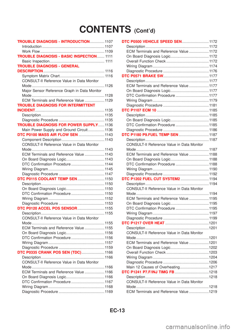
TROUBLE DIAGNOSIS - INTRODUCTION.............. 1107
Introduction ............................................................ 1107
Work Flow .............................................................. 1109
TROUBLE DIAGNOSIS - BASIC INSPECTION.......1111
Basic Inspection.....................................................1111
TROUBLE DIAGNOSIS - GENERAL
DESCRIPTION........................................................... 1116
Symptom Matrix Chart ........................................... 1116
CONSULT-II Reference Value in Data Monitor
Mode ...................................................................... 1126
Major Sensor Reference Graph in Data Monitor
Mode ...................................................................... 1128
ECM Terminals and Reference Value ................... 1129
TROUBLE DIAGNOSIS FOR INTERMITTENT
INCIDENT................................................................... 1135
Description ............................................................. 1135
Diagnostic Procedure ............................................ 1135
TROUBLE DIAGNOSIS FOR POWER SUPPLY...... 1136
Main Power Supply and Ground Circuit ................ 1136
DTC P0100 MASS AIR FLOW SEN......................... 1143
Component Description ......................................... 1143
CONSULT-II Reference Value in Data Monitor
Mode ...................................................................... 1143
ECM Terminals and Reference Value ................... 1143
On Board Diagnosis Logic..................................... 1143
DTC Confirmation Procedure ................................ 1144
Wiring Diagram ...................................................... 1145
Diagnostic Procedure ............................................ 1147
DTC P0115 COOLANT TEMP SEN.......................... 1150
Description ............................................................. 1150
On Board Diagnosis Logic..................................... 1150
DTC Confirmation Procedure ................................ 1150
Wiring Diagram ...................................................... 1152
Diagnostic Procedure ............................................ 1153
DTC P0120 ACCEL POS SENSOR.......................... 1155
Description ............................................................. 1155
CONSULT-II Reference Value in Data Monitor
Mode ...................................................................... 1155
ECM Terminals and Reference Value ................... 1155
On Board Diagnosis Logic..................................... 1156
DTC Confirmation Procedure ................................ 1156
Wiring Diagram ...................................................... 1157
Diagnostic Procedure ............................................ 1159
DTC P0335 CRANK POS SEN (TDC)...................... 1166
Description ............................................................. 1166
CONSULT-II Reference Value in Data Monitor
Mode ...................................................................... 1166
ECM Terminals and Reference Value ................... 1166
On Board Diagnosis Logic..................................... 1166
DTC Confirmation Procedure ................................ 1167
Wiring Diagram ...................................................... 1168
Diagnostic Procedure ............................................ 1169DTC P0500 VEHICLE SPEED SEN.......................... 1172
Description ............................................................. 1172
ECM Terminals and Reference Value ................... 1172
On Board Diagnosis Logic..................................... 1172
Overall Function Check ......................................... 1172
Wiring Diagram ...................................................... 1174
Diagnostic Procedure ............................................ 1176
DTC P0571 BRAKE SW............................................ 1177
Description ............................................................. 1177
ECM Terminals and Reference Value ................... 1177
On Board Diagnosis Logic..................................... 1177
DTC Confirmation Procedure ................................ 1177
Wiring Diagram ...................................................... 1179
Diagnostic Procedure ............................................ 1181
DTC P1107 ECM 10.................................................. 1185
Description ............................................................. 1185
On Board Diagnosis Logic..................................... 1185
DTC Confirmation Procedure ................................ 1185
Diagnostic Procedure ............................................ 1186
DTC P1180 P9.FUEL TEMP SEN............................. 1187
Description ............................................................. 1187
CONSULT-II Reference Value in Data Monitor
Mode ...................................................................... 1187
ECM Terminals and Reference Value ................... 1188
On Board Diagnosis Logic..................................... 1188
DTC Confirmation Procedure ................................ 1188
Wiring Diagram ...................................................... 1190
Diagnostic Procedure ............................................ 1192
DTC P1202 FUEL CUT SYSTEM2........................... 1194
Description ............................................................. 1194
CONSULT-II Reference Value in Data Monitor
Mode ...................................................................... 1194
ECM Terminals and Reference Value ................... 1195
On Board Diagnosis Logic..................................... 1195
DTC Confirmation Procedure ................................ 1195
Wiring Diagram ...................................................... 1197
Diagnostic Procedure ............................................ 1199
DTC P1217 OVER HEAT..........................................1201
Description .............................................................1201
CONSULT-II Reference Value in Data Monitor
Mode ......................................................................1201
ECM Terminals and Reference Value ...................1201
On Board Diagnosis Logic.....................................1202
Overall Function Check .........................................1203
Wiring Diagram ......................................................1204
Diagnostic Procedure ............................................1206
Main 12 Causes of Overheating............................1217
DTC P1241 P7.F/INJ TIMG FB.................................1218
Description .............................................................1218
CONSULT-II Reference Value in Data Monitor
Mode ......................................................................1218
ECM Terminals and Reference Value ...................1219
CONTENTS(Cont'd)
EC-13
Page 439 of 3051
On Board Diagnosis Logic.....................................1219
DTC Confirmation Procedure ................................1219
Wiring Diagram ......................................................1221
Diagnostic Procedure ............................................1223
DTC P1251 P4.SPILL/V CIRC..................................1225
Description .............................................................1225
CONSULT-II Reference Value in Data Monitor
Mode ......................................................................1225
ECM Terminals and Reference Value ...................1226
On Board Diagnosis Logic.....................................1226
DTC Confirmation Procedure ................................1226
Wiring Diagram ......................................................1228
Diagnostic Procedure ............................................1230
DTC P1337 P2.DTC PULSE SIG..............................1232
Description .............................................................1232
CONSULT-II Reference Value in Data Monitor
Mode ......................................................................1232
ECM Terminals and Reference Value ...................1233
On Board Diagnosis Logic.....................................1233
DTC Confirmation Procedure ................................1233
Wiring Diagram ......................................................1235
Diagnostic Procedure ............................................1237
DTC P1341 P1.CAM POS SEN................................1239
Description .............................................................1239
CONSULT-II Reference Value in Data Monitor
Mode ......................................................................1239
ECM Terminals and Reference Value ...................1240
On Board Diagnosis Logic.....................................1240
DTC Confirmation Procedure ................................1240
Wiring Diagram ......................................................1242
Diagnostic Procedure ............................................1244
DTC P1600 P3.PUMP COMM LINE..........................1246
Description .............................................................1246
CONSULT-II Reference Value in Data Monitor
Mode ......................................................................1246
ECM Terminals and Reference Value ...................1247
On Board Diagnosis Logic.....................................1247
DTC Confirmation Procedure ................................1247
Wiring Diagram ......................................................1249
Diagnostic Procedure ............................................1251
DTC P1603 ECM 12, DTC P1607 ECM 2.................1253
Description .............................................................1253
On Board Diagnosis Logic.....................................1253
DTC Confirmation Procedure ................................1253
Diagnostic Procedure ............................................1254
DTC P1620 ECM RLY...............................................1255
ECM Terminals and Reference Value ...................1255
On Board Diagnosis Logic.....................................1255
DTC Confirmation Procedure ................................1255
Wiring Diagram ......................................................1256
Diagnostic Procedure ............................................1258DTC P1621 ECM 15..................................................1260
Description .............................................................1260
On Board Diagnosis Logic.....................................1260
DTC Confirmation Procedure ................................1260
Diagnostic Procedure ............................................1261
DTC P1660 BATTERY VOLTAGE............................1262
On Board Diagnosis Logic.....................................1262
DTC Confirmation Procedure ................................1262
Diagnostic Procedure ............................................1262
DTC P1690 P5.PUMP C/MODULE...........................1264
Description .............................................................1264
CONSULT-II Reference Value in Data Monitor
Mode ......................................................................1264
ECM Terminals and Reference Value ...................1265
On Board Diagnosis Logic.....................................1265
DTC Confirmation Procedure ................................1265
Diagnostic Procedure ............................................1266
GLOW CONTROL SYSTEM.....................................1267
Description .............................................................1267
ECM Terminals and Reference Value ...................1268
Wiring Diagram ......................................................1269
Diagnostic Procedure ............................................1271
EGR VOLUME CONTROL SYSTEM........................1277
Description .............................................................1277
CONSULT-II Reference Value in Data Monitor
Mode ......................................................................1278
ECM Terminals and Reference Value ...................1278
Wiring Diagram ......................................................1279
Diagnostic Procedure ............................................1281
SWIRL CONTROL VALVE CONTROL SOLENOID
VALVE........................................................................1285
Description .............................................................1285
CONSULT-II Reference Value in Data Monitor
Mode ......................................................................1286
ECM Terminals and Reference Value ...................1286
Wiring Diagram ......................................................1287
Diagnostic Procedure ............................................1289
START SIGNAL.........................................................1293
Wiring Diagram ......................................................1293
Diagnostic Procedure ............................................1295
PARK/NEUTRAL POSITION (PNP) SWITCH
(WHERE FITTED)......................................................1297
Description .............................................................1297
CONSULT-II Reference Value in Data Monitor
Mode ......................................................................1297
ECM Terminals and Reference Value ...................1297
Wiring Diagram ......................................................1298
Diagnostic Procedure ............................................1299
AIR CONDITIONER CONTROL................................1301
Wiring Diagram ......................................................1301
MI & DATA LINK CONNECTORS............................1303
Wiring Diagram ......................................................1303
CONTENTS(Cont'd)
EC-14
Page 440 of 3051
SERVICE DATA AND SPECIFICATIONS (SDS).....1305
General Specifications ...........................................1305
Injection Nozzle .....................................................1305
Engine Coolant Temperature Sensor ....................1305Crankshaft Position Sensor (TDC) ........................1305
Glow Plug ..............................................................1305
Accelerator Position Sensor ..................................1305
EGR Volume Control Valve ...................................1305
CONTENTS(Cont'd)
EC-15