oil temperature NISSAN ALMERA TINO 2001 Service Service Manual
[x] Cancel search | Manufacturer: NISSAN, Model Year: 2001, Model line: ALMERA TINO, Model: NISSAN ALMERA TINO 2001Pages: 3051, PDF Size: 46.38 MB
Page 1420 of 3051
DescriptionNLEC1836SYSTEM DESCRIPTIONNLEC1836S01
Sensor Input Signal to ECMECM func-
tionActuator
Camshaft position sensor Engine speed
Idle air
controlIACV-AAC valve Mass air flow sensor Amount of intake air
Engine coolant temperature sensor Engine coolant temperature
Ignition switch Start signal
Throttle position sensor Throttle position
Park/neutral position (PNP) switch Park/neutral position
Air conditioner switch Air conditioner operation
Power steering oil pressure switch Power steering load signal
Battery Battery voltage
Vehicle speed sensor Vehicle speed
Intake air temperature sensor Intake air temperature
Cooling fan Cooling fan operation
Electrical load Electrical load signal
This system automatically controls engine idle speed to a specified
level. Idle speed is controlled through fine adjustment of the
amount of air which by-passes the throttle valve via IACV-AAC
valve. The IACV-AAC valve changes the opening of the air by-pass
passage to control the amount of auxiliary air. This valve is actu-
ated by a step motor built into the valve, which moves the valve in
the axial direction in steps corresponding to the ECM output sig-
nals. One step of IACV-AAC valve movement causes the respec-
tive opening of the air by-pass passage. (i.e. when the step
advances, the opening is enlarged.) The opening of the valve is
varied to allow for optimum control of the engine idling speed. The
camshaft position sensor detects the actual engine speed and
sends a signal to the ECM. The ECM then controls the step posi-
tion of the IACV-AAC valve so that engine speed coincides with the
target value memorized in ECM. The target engine speed is the
lowest speed at which the engine can operate steadily. The opti-
mum value stored in the ECM is determined by takig into consid-
eration various engine conditions, such as during warm up,
deceleration, and engine load (air conditioner, power steering and
cooling fan operation).
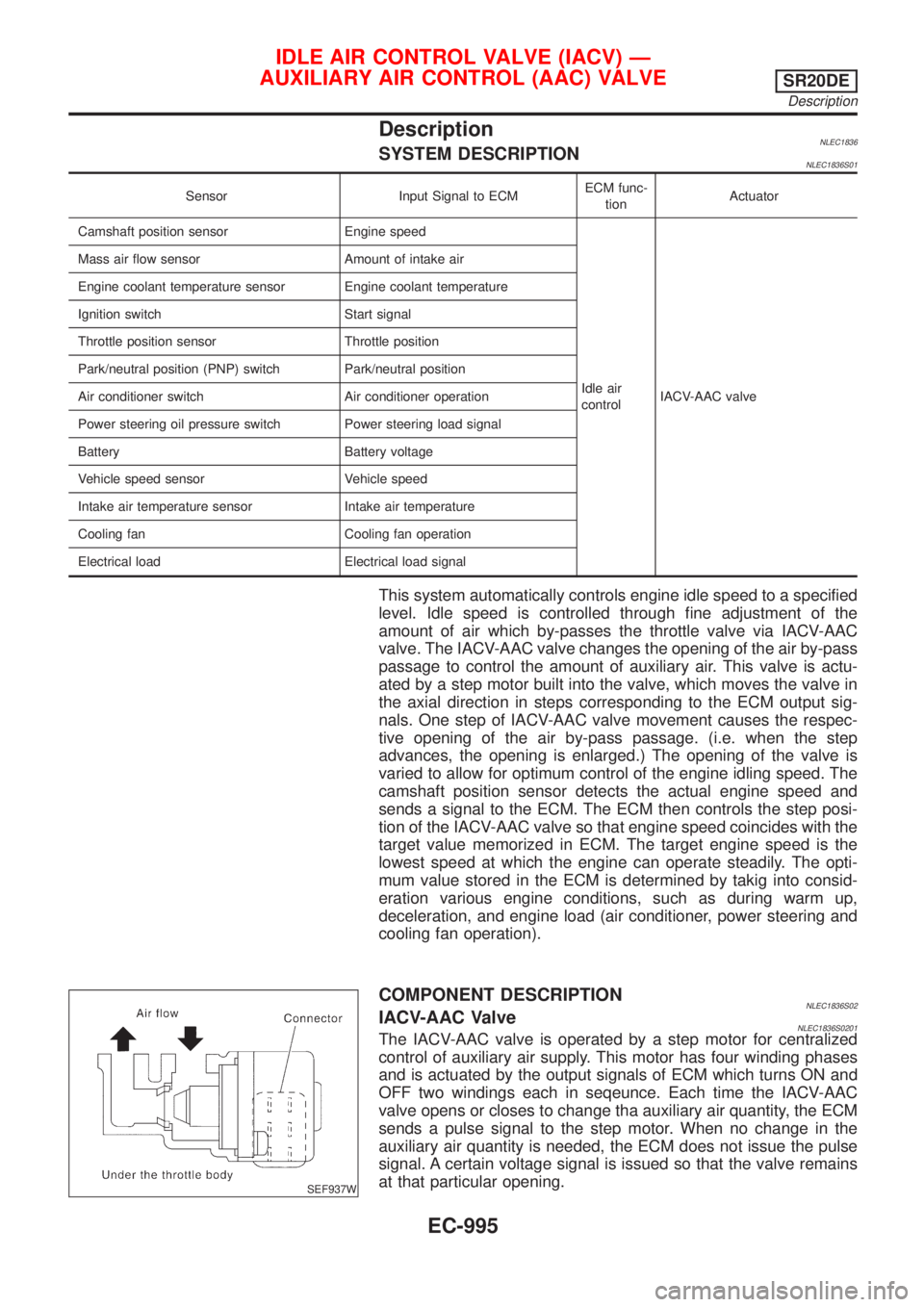
SEF937W
COMPONENT DESCRIPTIONNLEC1836S02IACV-AAC ValveNLEC1836S0201The IACV-AAC valve is operated by a step motor for centralized
control of auxiliary air supply. This motor has four winding phases
and is actuated by the output signals of ECM which turns ON and
OFF two windings each in seqeunce. Each time the IACV-AAC
valve opens or closes to change tha auxiliary air quantity, the ECM
sends a pulse signal to the step motor. When no change in the
auxiliary air quantity is needed, the ECM does not issue the pulse
signal. A certain voltage signal is issued so that the valve remains
at that particular opening.
IDLE AIR CONTROL VALVE (IACV) Ð
AUXILIARY AIR CONTROL (AAC) VALVE
SR20DE
Description
EC-995
Page 1487 of 3051
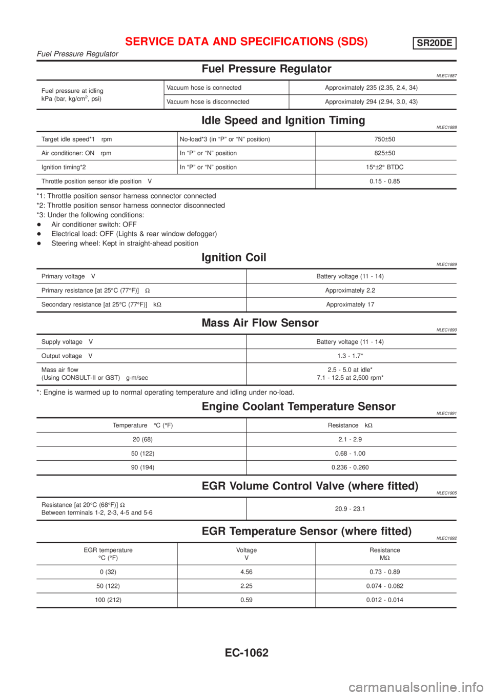
Fuel Pressure RegulatorNLEC1887
Fuel pressure at idling
kPa (bar, kg/cm2, psi)Vacuum hose is connected Approximately 235 (2.35, 2.4, 34)
Vacuum hose is disconnected Approximately 294 (2.94, 3.0, 43)
Idle Speed and Ignition TimingNLEC1888
Target idle speed*1 rpm No-load*3 (in ªPº or ªNº position) 750±50
Air conditioner: ON rpm In ªPº or ªNº position 825±50
Ignition timing*2 In ªPº or ªNº position 15ɱ2É BTDC
Throttle position sensor idle position V0.15 - 0.85
*1: Throttle position sensor harness connector connected
*2: Throttle position sensor harness connector disconnected
*3: Under the following conditions:
+Air conditioner switch: OFF
+Electrical load: OFF (Lights & rear window defogger)
+Steering wheel: Kept in straight-ahead position
Ignition CoilNLEC1889
Primary voltage VBattery voltage (11 - 14)
Primary resistance [at 25ÉC (77ÉF)]WApproximately 2.2
Secondary resistance [at 25ÉC (77ÉF)] kWApproximately 17
Mass Air Flow SensorNLEC1890
Supply voltage VBattery voltage (11 - 14)
Output voltage V1.3 - 1.7*
Mass air flow
(Using CONSULT-II or GST) g´m/sec2.5 - 5.0 at idle*
7.1 - 12.5 at 2,500 rpm*
*: Engine is warmed up to normal operating temperature and idling under no-load.
Engine Coolant Temperature SensorNLEC1891
Temperature ÉC (ÉF) Resistance kW
20 (68) 2.1 - 2.9
50 (122) 0.68 - 1.00
90 (194) 0.236 - 0.260
EGR Volume Control Valve (where fitted)NLEC1905
Resistance [at 20ÉC (68ÉF)]W
Between terminals 1-2, 2-3, 4-5 and 5-620.9 - 23.1
EGR Temperature Sensor (where fitted)NLEC1892
EGR temperature
ÉC (ÉF)Voltage
VResistance
MW
0 (32) 4.56 0.73 - 0.89
50 (122) 2.25 0.074 - 0.082
100 (212) 0.59 0.012 - 0.014
SERVICE DATA AND SPECIFICATIONS (SDS)SR20DE
Fuel Pressure Regulator
EC-1062
Page 1542 of 3051
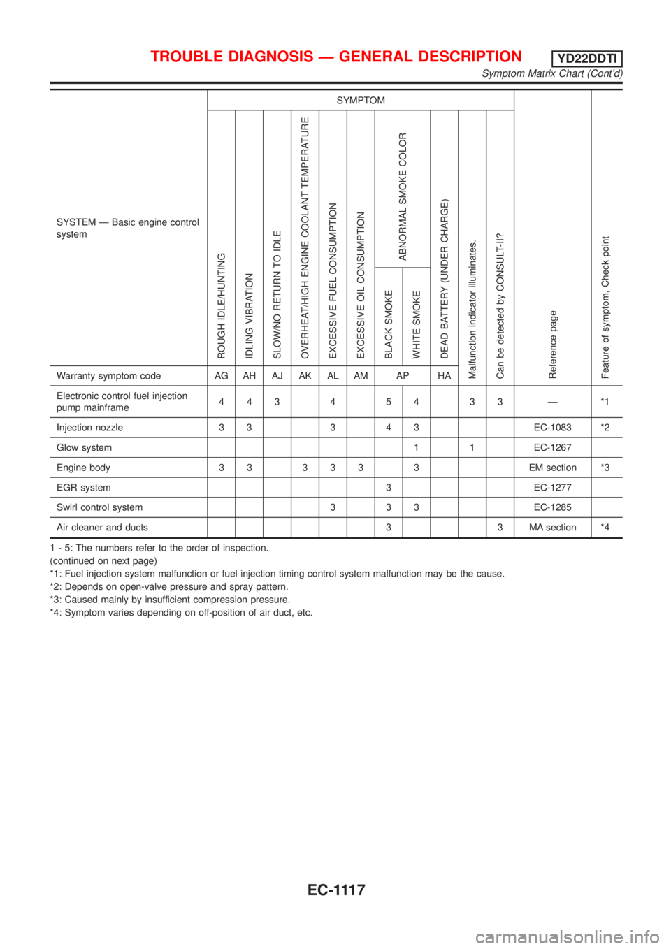
SYSTEM Ð Basic engine control
systemSYMPTOM
Reference page
Feature of symptom, Check pointROUGH IDLE/HUNTING
IDLING VIBRATION
SLOW/NO RETURN TO IDLE
OVERHEAT/HIGH ENGINE COOLANT TEMPERATURE
EXCESSIVE FUEL CONSUMPTION
EXCESSIVE OIL CONSUMPTION
ABNORMAL SMOKE COLOR
DEAD BATTERY (UNDER CHARGE)
Malfunction indicator illuminates.
Can be detected by CONSULT-II?BLACK SMOKE
WHITE SMOKEWarranty symptom code AG AH AJ AK AL AM AP HA
Electronic control fuel injection
pump mainframe44345433Ð*1
Injection nozzle 3 3 3 4 3 EC-1083 *2
Glow system 1 1 EC-1267
Engine body 3 3 3 3 3 3 EM section *3
EGR system 3 EC-1277
Swirl control system 3 3 3 EC-1285
Air cleaner and ducts 3 3 MA section *4
1 - 5: The numbers refer to the order of inspection.
(continued on next page)
*1: Fuel injection system malfunction or fuel injection timing control system malfunction may be the cause.
*2: Depends on open-valve pressure and spray pattern.
*3: Caused mainly by insufficient compression pressure.
*4: Symptom varies depending on off-position of air duct, etc.
TROUBLE DIAGNOSIS Ð GENERAL DESCRIPTIONYD22DDTI
Symptom Matrix Chart (Cont'd)
EC-1117
Page 1544 of 3051
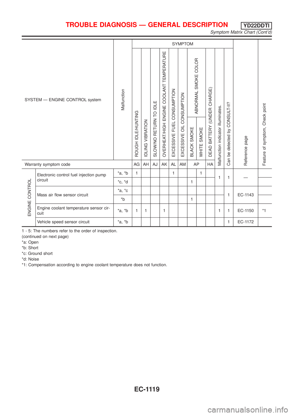
SYSTEM Ð ENGINE CONTROL system
Malfunction
SYMPTOM
Reference page
Feature of symptom, Check pointROUGH IDLE/HUNTING
IDLING VIBRATION
SLOW/NO RETURN TO IDLE
OVERHEAT/HIGH ENGINE COOLANT TEMPERATURE
EXCESSIVE FUEL CONSUMPTION
EXCESSIVE OIL CONSUMPTION
ABNORMAL SMOKE COLOR
DEAD BATTERY (UNDER CHARGE)
Malfunction indicator illuminates.
Can be detected by CONSULT-II?BLACK SMOKE
WHITE SMOKEWarranty symptom code AG AH AJ AK AL AM AP HA
ENGINE CONTROL
Electronic control fuel injection pump
circuit*a, *b 1 1 1
11 Ð
*c, *d 1
Mass air flow sensor circuit*a, *c
1 EC-1143
*b 1
Engine coolant temperature sensor cir-
cuit*a, *b 1 1 1 1 1 EC-1150 *1
Vehicle speed sensor circuit *a, *b 1 EC-1172
1 - 5: The numbers refer to the order of inspection.
(continued on next page)
*a: Open
*b: Short
*c: Ground short
*d: Noise
*1: Compensation according to engine coolant temperature does not function.
TROUBLE DIAGNOSIS Ð GENERAL DESCRIPTIONYD22DDTI
Symptom Matrix Chart (Cont'd)
EC-1119
Page 1546 of 3051
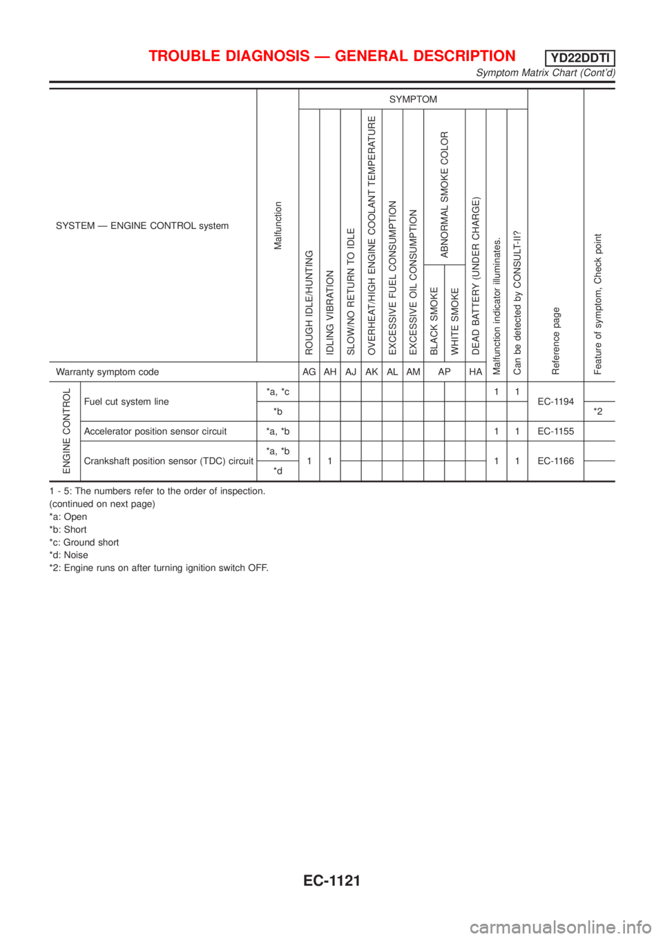
SYSTEM Ð ENGINE CONTROL system
Malfunction
SYMPTOM
Reference page
Feature of symptom, Check pointROUGH IDLE/HUNTING
IDLING VIBRATION
SLOW/NO RETURN TO IDLE
OVERHEAT/HIGH ENGINE COOLANT TEMPERATURE
EXCESSIVE FUEL CONSUMPTION
EXCESSIVE OIL CONSUMPTION
ABNORMAL SMOKE COLOR
DEAD BATTERY (UNDER CHARGE)
Malfunction indicator illuminates.
Can be detected by CONSULT-II?BLACK SMOKE
WHITE SMOKEWarranty symptom code AG AH AJ AK AL AM AP HA
ENGINE CONTROL
Fuel cut system line*a, *c 1 1
EC-1194
*b*2
Accelerator position sensor circuit *a, *b 1 1 EC-1155
Crankshaft position sensor (TDC) circuit*a, *b
1 1 1 1 EC-1166
*d
1 - 5: The numbers refer to the order of inspection.
(continued on next page)
*a: Open
*b: Short
*c: Ground short
*d: Noise
*2: Engine runs on after turning ignition switch OFF.
TROUBLE DIAGNOSIS Ð GENERAL DESCRIPTIONYD22DDTI
Symptom Matrix Chart (Cont'd)
EC-1121
Page 1548 of 3051
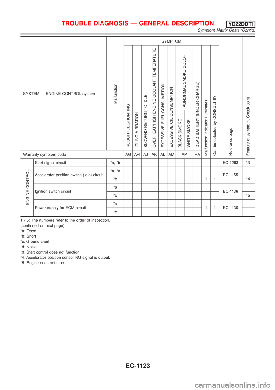
SYSTEM Ð ENGINE CONTROL system
Malfunction
SYMPTOM
Reference page
Feature of symptom, Check pointROUGH IDLE/HUNTING
IDLING VIBRATION
SLOW/NO RETURN TO IDLE
OVERHEAT/HIGH ENGINE COOLANT TEMPERATURE
EXCESSIVE FUEL CONSUMPTION
EXCESSIVE OIL CONSUMPTION
ABNORMAL SMOKE COLOR
DEAD BATTERY (UNDER CHARGE)
Malfunction indicator illuminates.
Can be detected by CONSULT-II?BLACK SMOKE
WHITE SMOKEWarranty symptom code AG AH AJ AK AL AM AP HA
ENGINE CONTROL
Start signal circuit *a, *b EC-1293 *3
Accelerator position switch (Idle) circuit*a, *c
EC-1155
*b 1 1 *4
Ignition switch circuit*a
EC-1136
*b*5
Power supply for ECM circuit*a
1 1 EC-1136
*b
1 - 5: The numbers refer to the order of inspection.
(continued on next page)
*a: Open
*b: Short
*c: Ground short
*d: Noise
*3: Start control does not function.
*4: Accelerator position sensor NG signal is output.
*5: Engine does not stop.
TROUBLE DIAGNOSIS Ð GENERAL DESCRIPTIONYD22DDTI
Symptom Matrix Chart (Cont'd)
EC-1123
Page 1550 of 3051
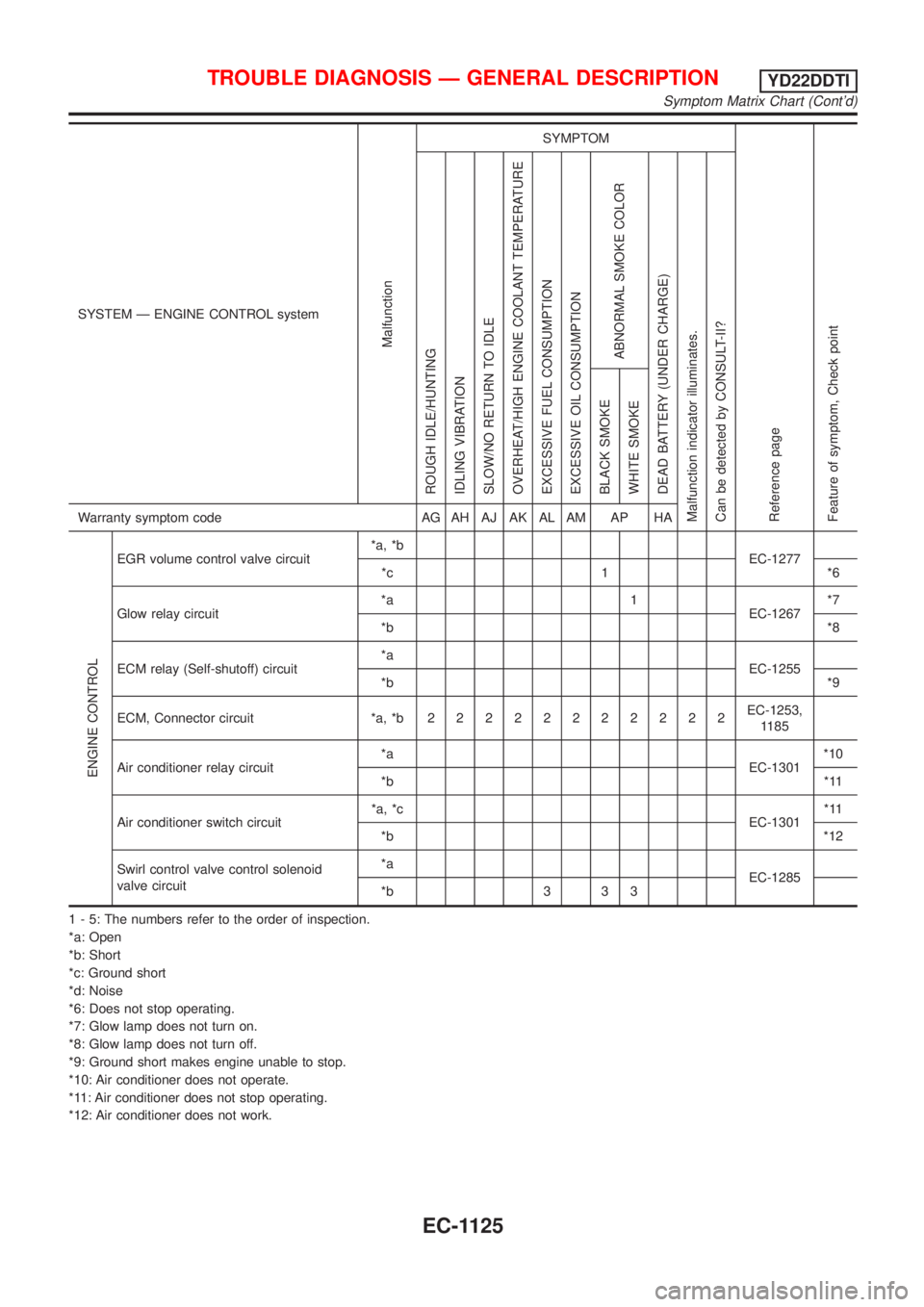
SYSTEM Ð ENGINE CONTROL system
Malfunction
SYMPTOM
Reference page
Feature of symptom, Check pointROUGH IDLE/HUNTING
IDLING VIBRATION
SLOW/NO RETURN TO IDLE
OVERHEAT/HIGH ENGINE COOLANT TEMPERATURE
EXCESSIVE FUEL CONSUMPTION
EXCESSIVE OIL CONSUMPTION
ABNORMAL SMOKE COLOR
DEAD BATTERY (UNDER CHARGE)
Malfunction indicator illuminates.
Can be detected by CONSULT-II?BLACK SMOKE
WHITE SMOKEWarranty symptom code AG AH AJ AK AL AM AP HA
ENGINE CONTROL
EGR volume control valve circuit*a, *b
EC-1277
*c 1 *6
Glow relay circuit*a 1
EC-1267*7
*b*8
ECM relay (Self-shutoff) circuit*a
EC-1255
*b*9
ECM, Connector circuit *a, *b22222222222EC-1253,
1185
Air conditioner relay circuit*a
EC-1301*10
*b*11
Air conditioner switch circuit*a, *c
EC-1301*11
*b*12
Swirl control valve control solenoid
valve circuit*a
EC-1285
*b 3 3 3
1 - 5: The numbers refer to the order of inspection.
*a: Open
*b: Short
*c: Ground short
*d: Noise
*6: Does not stop operating.
*7: Glow lamp does not turn on.
*8: Glow lamp does not turn off.
*9: Ground short makes engine unable to stop.
*10: Air conditioner does not operate.
*11: Air conditioner does not stop operating.
*12: Air conditioner does not work.
TROUBLE DIAGNOSIS Ð GENERAL DESCRIPTIONYD22DDTI
Symptom Matrix Chart (Cont'd)
EC-1125
Page 1627 of 3051
![NISSAN ALMERA TINO 2001 Service Service Manual TERMI-
NAL
NO.WIRE
COLORITEM CONDITION DATA(DC Voltage)
221 LG/B Cooling fan relay (High)[Engine is running]
+Cooling fans are not operating
+Cooling fans are operating at low speedBATTERY VOLTAGE
(11 NISSAN ALMERA TINO 2001 Service Service Manual TERMI-
NAL
NO.WIRE
COLORITEM CONDITION DATA(DC Voltage)
221 LG/B Cooling fan relay (High)[Engine is running]
+Cooling fans are not operating
+Cooling fans are operating at low speedBATTERY VOLTAGE
(11](/img/5/57352/w960_57352-1626.png)
TERMI-
NAL
NO.WIRE
COLORITEM CONDITION DATA(DC Voltage)
221 LG/B Cooling fan relay (High)[Engine is running]
+Cooling fans are not operating
+Cooling fans are operating at low speedBATTERY VOLTAGE
(11 - 14V)
[Engine is running]
+Cooling fans are operating at high speedApproximately 0.1V
On Board Diagnosis LogicNLEC0663This diagnosis continuously monitors the engine coolant temperature.
If the cooling fan or another component in the cooling system malfunctions, engine coolant temperature will
rise.
When the engine coolant temperature reaches an abnormally high temperature condition, a malfunction is
indicated.
DTC Malfunction is detected when ... Check Items (Possible Cause)
P1217
0208+Cooling fan does not operate properly (Overheat).
+Cooling fan system does not operate properly
(Overheat).
+Engine coolant was not added to the system using
the proper filling method.+Harness or connectors
(The cooling fan circuit is open or shorted.)
+Cooling fan
+Radiator hose
+Radiator
+Radiator cap
+Water pump
+Thermostat
+Engine coolant temperature sensor
For more information, refer to ªMAIN 12 CAUSES OF
OVERHEATINGº, EC-1217.
CAUTION:
When a malfunction is indicated, be sure to replace the coolant following the procedure in the LC-59,
ªChanging Engine Coolantº. Also, replace the engine oil.
1) Fill radiator with coolant up to specified level with a filling speed of 2 liters per minute. Be sure
to use coolant with the proper mixture ratio. Refer to MA-22, ªEngine Coolant Mixture Ratioº.
2) After refilling coolant, run engine to ensure that no water-flow noise is emitted.
DTC P1217 OVER HEATYD22DDTI
ECM Terminals and Reference Value (Cont'd)
EC-1202
Page 2269 of 3051
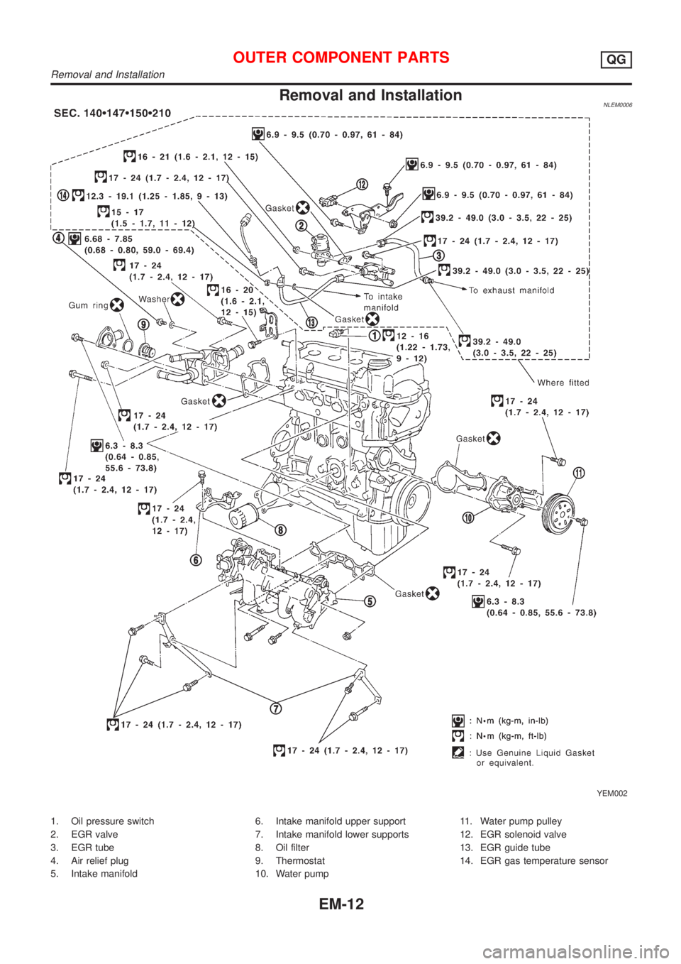
Removal and InstallationNLEM0006
YEM002
1. Oil pressure switch
2. EGR valve
3. EGR tube
4. Air relief plug
5. Intake manifold6. Intake manifold upper support
7. Intake manifold lower supports
8. Oil filter
9. Thermostat
10. Water pump11. Water pump pulley
12. EGR solenoid valve
13. EGR guide tube
14. EGR gas temperature sensor
OUTER COMPONENT PARTSQG
Removal and Installation
EM-12
Page 2272 of 3051
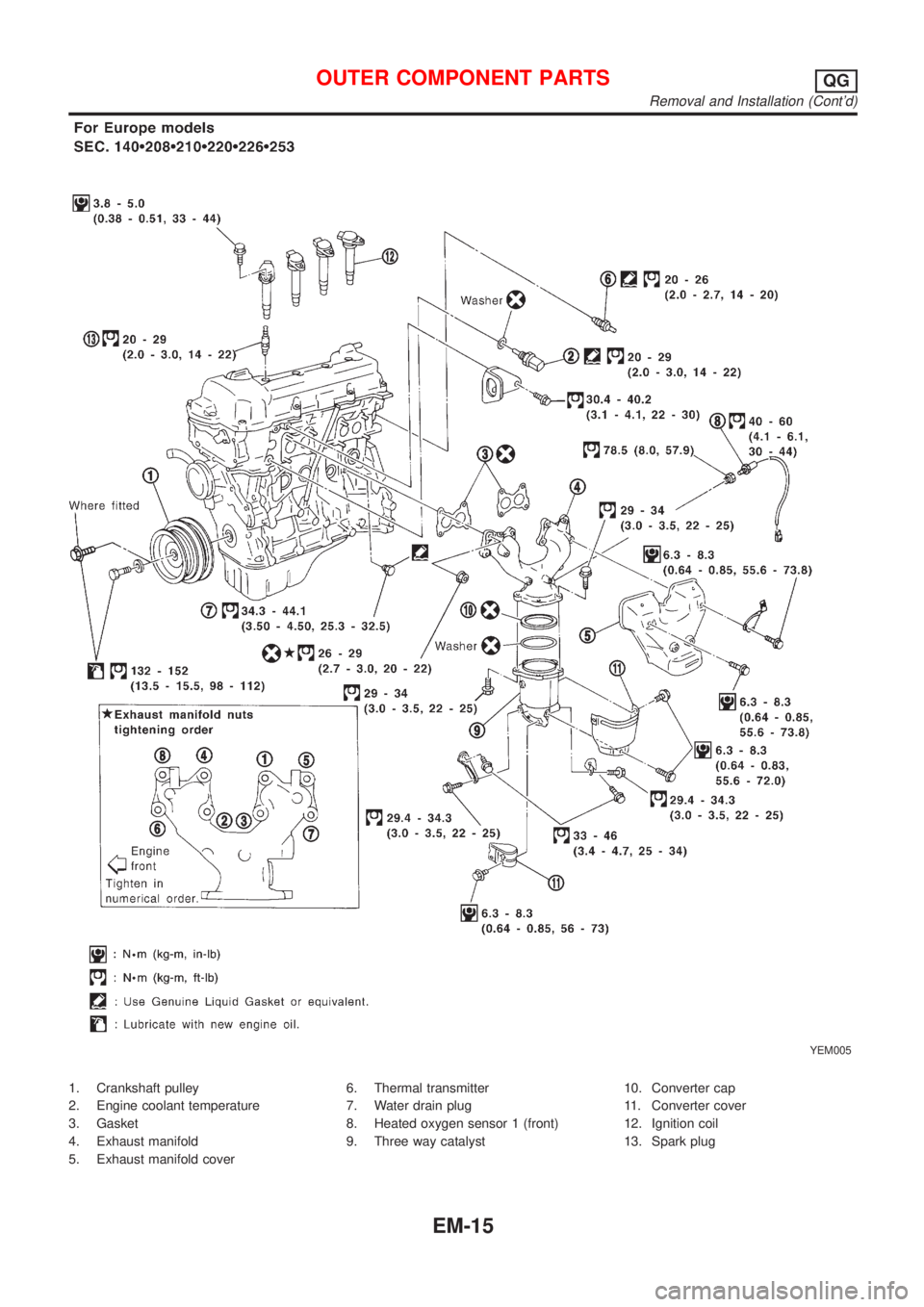
YEM005
1. Crankshaft pulley
2. Engine coolant temperature
3. Gasket
4. Exhaust manifold
5. Exhaust manifold cover6. Thermal transmitter
7. Water drain plug
8. Heated oxygen sensor 1 (front)
9. Three way catalyst10. Converter cap
11. Converter cover
12. Ignition coil
13. Spark plug
OUTER COMPONENT PARTSQG
Removal and Installation (Cont'd)
EM-15