oil temperature NISSAN ALMERA TINO 2001 Service Manual PDF
[x] Cancel search | Manufacturer: NISSAN, Model Year: 2001, Model line: ALMERA TINO, Model: NISSAN ALMERA TINO 2001Pages: 3051, PDF Size: 46.38 MB
Page 2700 of 3051
Headlamp .................................................. EL-69
Headlining - See Roof trim ........................ BT-35
Heated oxygen sensor (HO2S)
(front) . EC-184, 192, 198, 204, 214, 414, 709,
717, 723, 729, 739, 944
Heated oxygen sensor (HO2S) heater
(front) .......................... EC-221, 421, 746, 951
Heated oxygen sensor (HO2S) heater
(rear) ........................... EC-263, 433, 786, 963
Heated oxygen sensor (rear) . EC-227, 237, 246,
256, 426, 752, 761, 770, 779, 956
Heated seat ............................................. EL-234
Height (Dimensions) ................................... GI-41
Hood ............................................................ BT-7
Horn ......................................................... EL-193
How to erase DTC for OBD system .. EC-69, 71,
594, 596, 1096
I
IACV-AAC valve ............. EC-343, 466, 863, 995
IATS - Wiring diagram .... EC-163, 409, 689, 939
IGN/SG - Wiring diagram ................ EC-501, 903
ILL - Wiring diagram ................................ EL-109
INJECT - Wiring diagram .............. EC-495, 1022
IVC - Wiring diagram ...................... EC-362, 476
Identification plate ...................................... GI-39
Idle air control (IAC) system .......... EC-343, 466,
863, 995
Idle air control valve (IACV) ........... EC-343, 466,
863, 995
Idle speed ........................................ EC-46,1111
Ignition coil .................................... EC-907, 1010
Ignition control system ............................ EC-500
Ignition timing ............................................ EC-46
Ignition wire inspection ........................... EC-814
Illumination ............................................... EL-107
Injection nozzle ..................................... EC-1083
Injector removal and installation ....... EC-44, 578
Input shaft (FF M/T) ..................... MT-34, 63, 68
Instrument panel ........................................ BT-22
Intake air temperature sensor ........ EC-161, 407,
687, 937
Intake valve timing control solenoid
valve ............................................ EC-360, 475
Interior lamp on-off control ....................... EL-117
Interior lamp ............................................. EL-116
Interior ........................................................ BT-28
J
Jacking points ............................................ GI-43
Joint connector (J/C) ............................... EL-531
Junction box (J/B) .................................... EL-527
K
KS - Wiring diagram ............................... EC-292
Keyless entry system - See Multi-re-
mote control system ............................. EL-314
Knock sensor (KS) ................. EC-291, 815, 816
Knuckle spindle ........................................... AX-5
L
LOAD - Wiring diagram ................ EC-536, 1051
Length (Dimensions) .................................. GI-41
License lamp ............................................. EL-87
Lifting points ............................................... GI-44
Line pressure test (A/T) ............................. AT-52
Liquid gasket application .............. EM-5, 76, 158
Location of electrical units ....................... EL-442
Lock, door .................................................. BT-18
Lubricant (R134a) A/C .............................. HA-87
Lubricants ................................................. MA-20
Lubrication circuit (engine) .............. LC-4, 24, 43
M
M/T major overhaul ............................. MT-24, 62
M/T removal and installation ..................... MT-18
MAFS - Wiring diagram ........ EC-156, 682, 1143
MAIN - Wiring diagram ......... EC-146, 671, 1136
MIL & Data link connectors circuit ......... EC-545,
1060
MIL/DL - Wiring diagram .... EC-545, 1060, 1303
MIRROR - Wiring diagram ...................... EL-241
Magnet clutch ............................................ HA-90
Mainshaft (M/T) ............................ MT-39, 63, 73
Malfunction indicator lamp (MIL) .............. EC-73,
598, 1097
Manual air conditioner - Wiring
diagram .................................................. HA-27
Manual transaxle number .......................... GI-40
Mass air flow sensor (MAFS) ................ EC-154,
679, 1143
Master cylinder (clutch) ............................. CL-11
Meter ........................................................ EL-130
Mirror defogger ........................................ EL-198
Mirror, door ................................................ BT-63
Misfire ............................................. EC-285, 808
Mode door control linkage
adjustment ............................................. HA-48
Model variation ........................................... GI-37
Molding - See Exterior ............................... BT-38
Multi-remote control system .................... EL-314
Multiport fuel injection (MFI) system . EC-35, 569
Multiport fuel injection precautions ............... GI-6
ALPHABETICAL INDEX
IDX-5
Page 2708 of 3051
SEM853F
Oil Pressure CheckNLLC0004WARNING:
+Be careful not to burn yourself, as the engine and oil may
be hot.
+For M/T models, put gearshift lever in Neutral ªNº posi-
tion.
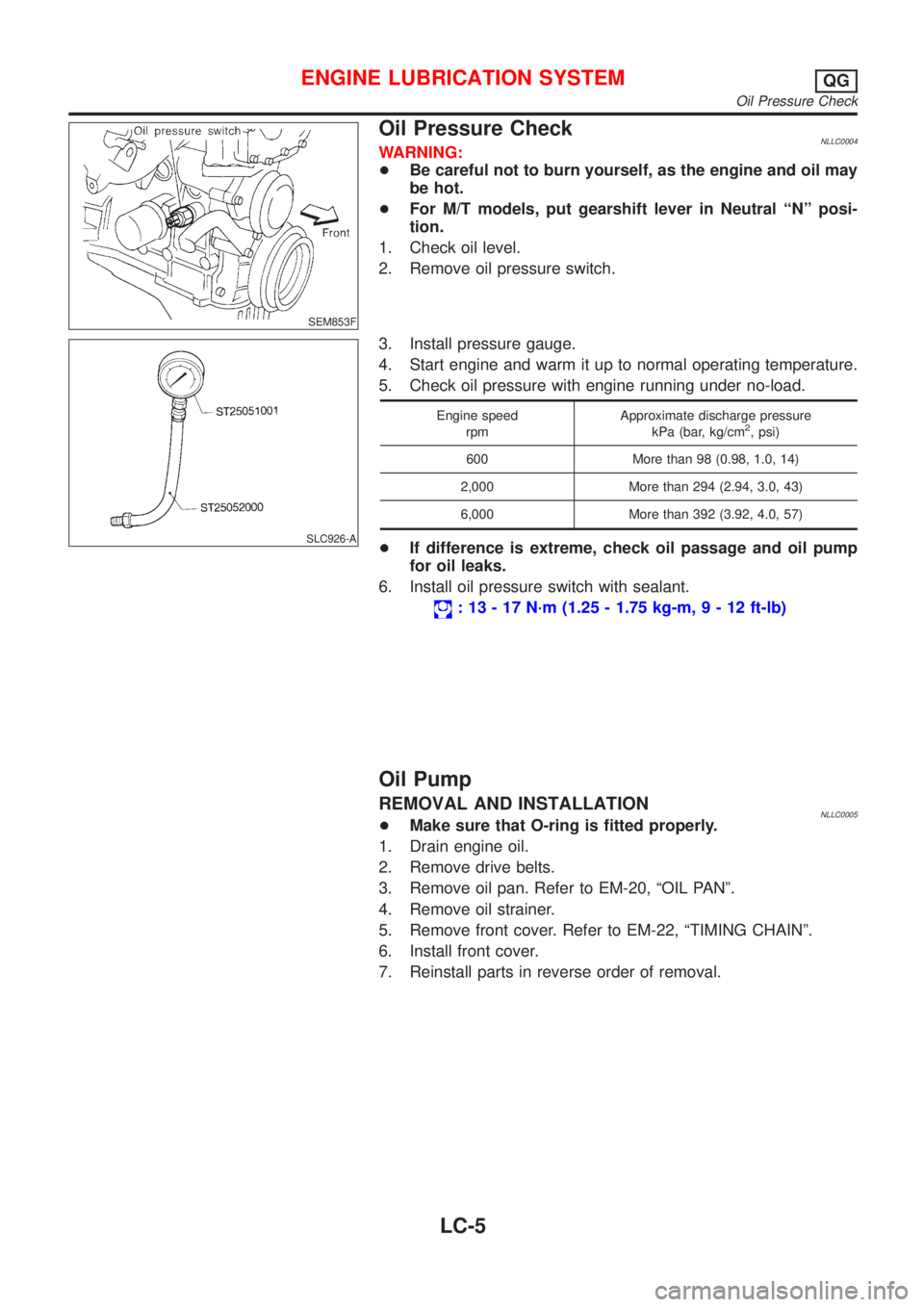
1. Check oil level.
2. Remove oil pressure switch.
SLC926-A
3. Install pressure gauge.
4. Start engine and warm it up to normal operating temperature.
5. Check oil pressure with engine running under no-load.
Engine speed
rpmApproximate discharge pressure
kPa (bar, kg/cm2, psi)
600 More than 98 (0.98, 1.0, 14)
2,000 More than 294 (2.94, 3.0, 43)
6,000 More than 392 (3.92, 4.0, 57)
+If difference is extreme, check oil passage and oil pump
for oil leaks.
6. Install oil pressure switch with sealant.
: 13 - 17 N´m (1.25 - 1.75 kg-m,9-12ft-lb)
Oil Pump
REMOVAL AND INSTALLATIONNLLC0005+Make sure that O-ring is fitted properly.
1. Drain engine oil.
2. Remove drive belts.
3. Remove oil pan. Refer to EM-20, ªOIL PANº.
4. Remove oil strainer.
5. Remove front cover. Refer to EM-22, ªTIMING CHAINº.
6. Install front cover.
7. Reinstall parts in reverse order of removal.
ENGINE LUBRICATION SYSTEMQG
Oil Pressure Check
LC-5
Page 2728 of 3051
NLC045
Oil Pressure CheckNLLC0116WARNING:
+Be careful not to burn yourself, as the engine and oil may
be hot.
+For A/T models, put selector lever in Park ªPº position.
1. Check oil level.
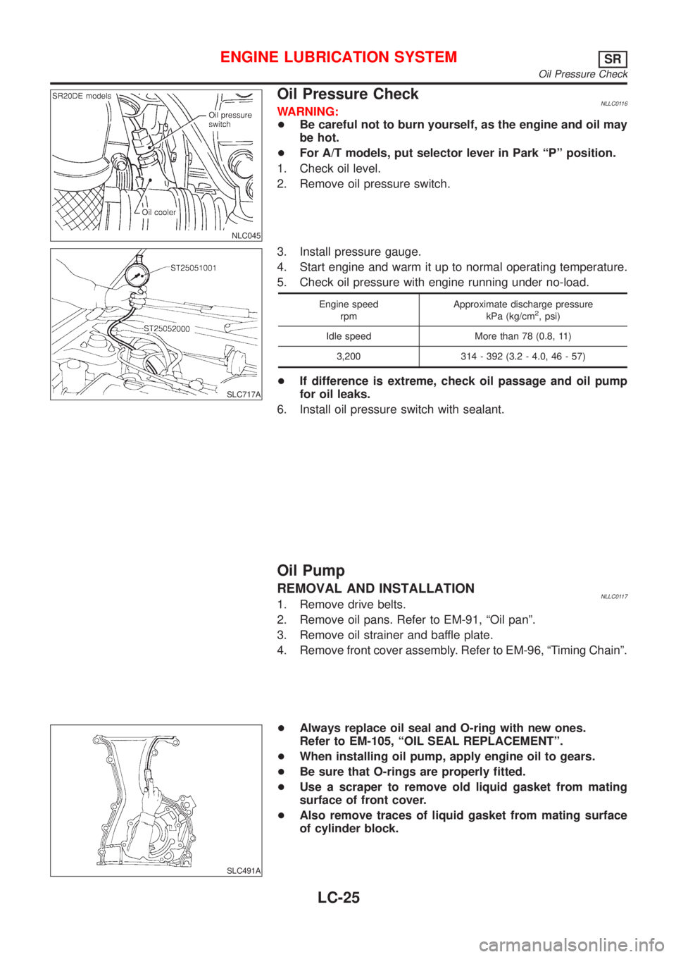
2. Remove oil pressure switch.
SLC717A
3. Install pressure gauge.
4. Start engine and warm it up to normal operating temperature.
5. Check oil pressure with engine running under no-load.
Engine speed
rpmApproximate discharge pressure
kPa (kg/cm2, psi)
Idle speed More than 78 (0.8, 11)
3,200 314 - 392 (3.2 - 4.0, 46 - 57)
+If difference is extreme, check oil passage and oil pump
for oil leaks.
6. Install oil pressure switch with sealant.
Oil Pump
REMOVAL AND INSTALLATIONNLLC01171. Remove drive belts.
2. Remove oil pans. Refer to EM-91, ªOil panº.
3. Remove oil strainer and baffle plate.
4. Remove front cover assembly. Refer to EM-96, ªTiming Chainº.
SLC491A
+Always replace oil seal and O-ring with new ones.
Refer to EM-105, ªOIL SEAL REPLACEMENTº.
+When installing oil pump, apply engine oil to gears.
+Be sure that O-rings are properly fitted.
+Use a scraper to remove old liquid gasket from mating
surface of front cover.
+Also remove traces of liquid gasket from mating surface
of cylinder block.
ENGINE LUBRICATION SYSTEMSR
Oil Pressure Check
LC-25
Page 2731 of 3051
NMA039
Changing Engine OilNLLC0125WARNING:
+Be careful not to burn yourself, as the engine oil is hot.
+Prolonged and repeated contact with used engine oil may
cause skin cancer; try to avoid direct skin contact with
used oil. If skin contact is made, wash thoroughly with
soap or hand cleaner as soon as possible.
1. Warm up engine, and check for oil leakage from engine com-
ponents.
2. Stop engine.
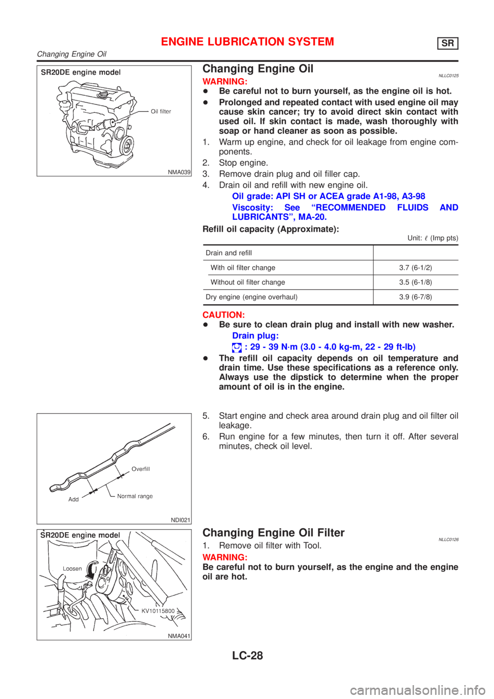
3. Remove drain plug and oil filler cap.
4. Drain oil and refill with new engine oil.
Oil grade: API SH or ACEA grade A1-98, A3-98
Viscosity: See ªRECOMMENDED FLUIDS AND
LUBRICANTSº, MA-20.
Refill oil capacity (Approximate):
Unit:!(Imp pts)
Drain and refill
With oil filter change 3.7 (6-1/2)
Without oil filter change 3.5 (6-1/8)
Dry engine (engine overhaul) 3.9 (6-7/8)
CAUTION:
+Be sure to clean drain plug and install with new washer.
Drain plug:
: 29 - 39 N´m (3.0 - 4.0 kg-m, 22 - 29 ft-lb)
+The refill oil capacity depends on oil temperature and
drain time. Use these specifications as a reference only.
Always use the dipstick to determine when the proper
amount of oil is in the engine.
NDI021
5. Start engine and check area around drain plug and oil filter oil
leakage.
6. Run engine for a few minutes, then turn it off. After several
minutes, check oil level.
NMA041
Changing Engine Oil FilterNLLC01261. Remove oil filter with Tool.
WARNING:
Be careful not to burn yourself, as the engine and the engine
oil are hot.
ENGINE LUBRICATION SYSTEMSR
Changing Engine Oil
LC-28
Page 2747 of 3051
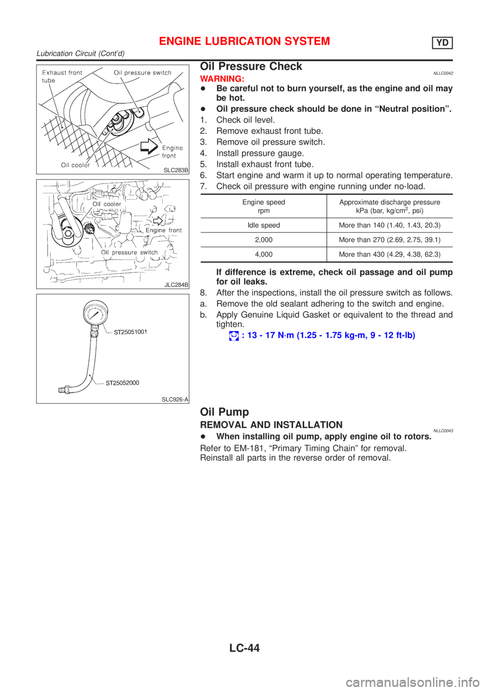
SLC283B
JLC284B
SLC926-A
Oil Pressure CheckNLLC0042WARNING:
+Be careful not to burn yourself, as the engine and oil may
be hot.
+Oil pressure check should be done in ªNeutral positionº.
1. Check oil level.
2. Remove exhaust front tube.
3. Remove oil pressure switch.
4. Install pressure gauge.
5. Install exhaust front tube.
6. Start engine and warm it up to normal operating temperature.
7. Check oil pressure with engine running under no-load.
Engine speed
rpmApproximate discharge pressure
kPa (bar, kg/cm2, psi)
Idle speed More than 140 (1.40, 1.43, 20.3)
2,000 More than 270 (2.69, 2.75, 39.1)
4,000 More than 430 (4.29, 4.38, 62.3)
If difference is extreme, check oil passage and oil pump
for oil leaks.
8. After the inspections, install the oil pressure switch as follows.
a. Remove the old sealant adhering to the switch and engine.
b. Apply Genuine Liquid Gasket or equivalent to the thread and
tighten.
: 13 - 17 N´m (1.25 - 1.75 kg-m,9-12ft-lb)
Oil Pump
REMOVAL AND INSTALLATIONNLLC0043+When installing oil pump, apply engine oil to rotors.
Refer to EM-181, ªPrimary Timing Chainº for removal.
Reinstall all parts in the reverse order of removal.
ENGINE LUBRICATION SYSTEMYD
Lubrication Circuit (Cont'd)
LC-44
Page 2750 of 3051
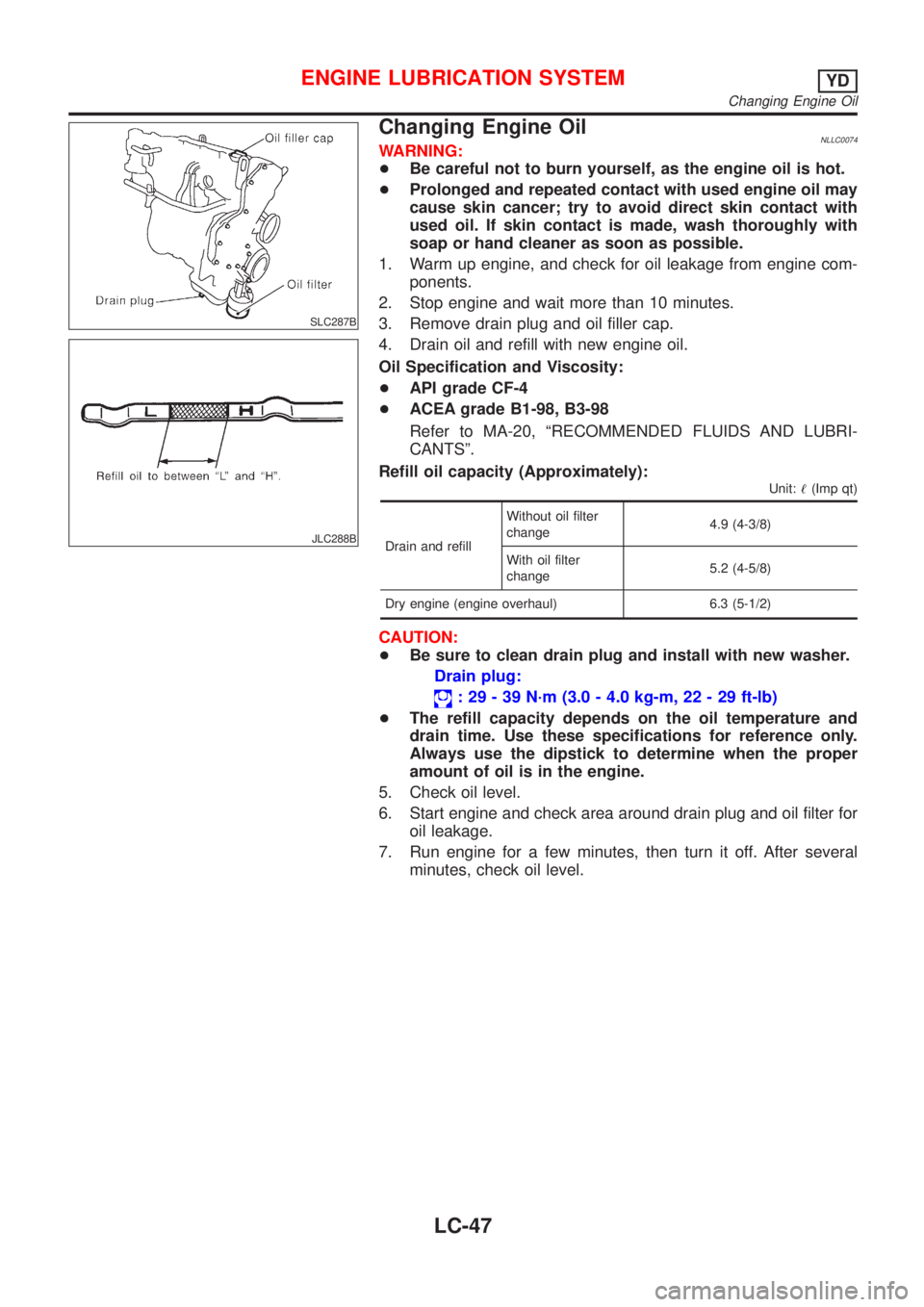
SLC287B
JLC288B
Changing Engine OilNLLC0074WARNING:
+Be careful not to burn yourself, as the engine oil is hot.
+Prolonged and repeated contact with used engine oil may
cause skin cancer; try to avoid direct skin contact with
used oil. If skin contact is made, wash thoroughly with
soap or hand cleaner as soon as possible.
1. Warm up engine, and check for oil leakage from engine com-
ponents.
2. Stop engine and wait more than 10 minutes.
3. Remove drain plug and oil filler cap.
4. Drain oil and refill with new engine oil.
Oil Specification and Viscosity:
+API grade CF-4
+ACEA grade B1-98, B3-98
Refer to MA-20, ªRECOMMENDED FLUIDS AND LUBRI-
CANTSº.
Refill oil capacity (Approximately):
Unit:!(Imp qt)
Drain and refillWithout oil filter
change4.9 (4-3/8)
With oil filter
change5.2 (4-5/8)
Dry engine (engine overhaul) 6.3 (5-1/2)
CAUTION:
+Be sure to clean drain plug and install with new washer.
Drain plug:
: 29 - 39 N´m (3.0 - 4.0 kg-m, 22 - 29 ft-lb)
+The refill capacity depends on the oil temperature and
drain time. Use these specifications for reference only.
Always use the dipstick to determine when the proper
amount of oil is in the engine.
5. Check oil level.
6. Start engine and check area around drain plug and oil filter for
oil leakage.
7. Run engine for a few minutes, then turn it off. After several
minutes, check oil level.
ENGINE LUBRICATION SYSTEMYD
Changing Engine Oil
LC-47
Page 2775 of 3051

Maintenance Under Severe Driving Conditions=NLMA0046S04The maintenance intervals shown on the preceding pages are for normal operating conditions. If the vehicle
is mainly operated under severe driving conditions as shown below, more frequent maintenance must be per-
formed on the following items as shown in the table.
SEVERE DRIVING CONDITIONSNLMA0046S0401A—Driving under dusty conditions
B—Driving repeatedly short distances
C—Towing a trailer or caravan
D—Extensive idling
E—Driving in extremely adverse weather conditions or in areas where ambient temperatures are either
extremely low or extremely high
F—Driving in high humidity areas or in mountainous areas
G—Driving in areas using salt or other corrosive materials
H—Driving on rough and/or muddy roads or in the desert
I—Driving with frequent use of braking or in mountainous areas
Driving condition Maintenance itemMaintenance
operationMaintenance
intervalRefer-
ence
page
A........Aircleaner filter Viscous paper type Replace More frequentlyEM-18,
EM-88,
EM-169
ABCD.....Engine oil & oil filter (QG18DE/SR20DE
engine)ReplaceEvery 5,000 km
(3,000 miles) or 3
monthsLC-8,
LC-28,
LC-9,
LC-28
ABCD.....Engine oil (YD22DDTi engine)
ReplaceMore frequently LC-47
Engine oil filter (YD22DDTi engine)Every 7,500 km
(4,500 miles) or 6
monthsLC-48
A...E....Fuel filter (YD22DDTi engine) ReplaceEvery 20,000 km
(12,000 miles) or
12 monthsFE-15
.....F...Brake fluid ReplaceEvery 20,000 km
(12,000 miles) or
12 monthsBR-7
..C....H.H·CVT fluid ReplaceEvery 20,000 km
(12,000 miles) or
12 monthsAT-11
......GH.Steering gear & linkage, axle & suspen-
sion parts & drive shaftsCheckEvery 10,000 km
(6,000 miles) or 6
monthsST-7,
SU-5,
SU-18
A.C...GHIBrake pads, rotors & other brake com-
ponentsCheckEvery 5,000 km
(3,000 miles) or 3
monthsBR-24,
BR-28
......G..Lock, hinges & hood latch LubricateEvery 5,000 km
(3,000 miles) or 3
monthsBT-7,
BT-13
A........Ventilation air filter Replace More frequently HA-103
PERIODIC MAINTENANCE (EXCEPT FOR EUROPE)
Maintenance Under Severe Driving Conditions
MA-8
Page 2780 of 3051

Maintenance Under Severe Driving Conditions
(Annual Driving Distance < 30,000 km/year)
=NLMA0043S03The maintenance intervals shown on the preceding pages are for normal operating conditions. If the vehicle
is mainly operated under severe driving conditions as shown below, more frequent maintenance must be per-
formed on the following items as shown in the table.
A—Driving under dusty conditions
B—Driving repeatedly short distances
C—Towing a trailer or caravan
D—Extensive idling
E—Driving in extremely adverse weather conditions or in areas where ambient temperatures are either
extremely low or extremely high
F—Driving in high humidity areas or in mountainous areas
G—Driving in areas using salt or other corrosive materials
H—Driving on rough and/or muddy roads or in the desert
I—Driving with frequent use of braking or in mountainous areas
J—Frequent off road use or driving in water
K—Sustained high speed driving
L—For models without Euro-OBD system
Driving conditionMaintenance
itemMaintenance
operationMaintenance interval
ABCD........Engine oil & engine oil filter
Petrol models ReplaceEvery 7,500 km (4,500 miles) or 6
months
Diesel models ReplaceEvery 10,000 km (6,000 miles) or
6 months
A...........Air cleaner filter
Petrol models ReplaceEvery 30,000 km (18,000 miles) or
24 months
Diesel models ReplaceEvery 30,000 km (18,000 miles) or
18 months
A...E.......Fuel filter
Diesel models ReplaceEvery 20,000 km (12,000 miles) or
12 months
A...........Ventilation air filter
Petrol models ReplaceEvery 15,000 km (9,000 miles) or
12 months
Diesel models ReplaceEvery 10,000 km (6,000 miles) or
6 months
.....F......Brake fluid
Petrol models ReplaceEvery 15,000 km (9,000 miles) or
12 months
Diesel models ReplaceEvery 20,000 km (12,000 miles) or
12 months
A.C...GHI...Brake pads, rotors & other brake system components
Petrol models InspectEvery 7,500 km (4,500 miles) or 6
months
Diesel models InspectEvery 10,000 km (6,000 miles) or
6 months
PERIODIC MAINTENANCE
Maintenance Under Severe Driving Conditions (Annual Driving Distance < 30,000 km/year)
MA-13
Page 2786 of 3051

Maintenance Under Severe Driving Conditions
(Annual Driving Distance > 30,000 km/year)
=NLMA0043S06The maintenance intervals shown on the preceding pages are for normal operating conditions. If the vehicle
is mainly operated under severe driving conditions as shown below, more frequent maintenance must be per-
formed on the following items as shown in the table.
A—Driving under dusty conditions
B—Driving repeatedly short distances
C—Towing a trailer or caravan
D—Extensive idling
E—Driving in extremely adverse weather conditions or in areas where ambient temperatures are either
extremely low or extremely high
F—Driving in high humidity areas or in mountainous areas
G—Driving in areas using salt or other corrosive materials
H—Driving on rough and/or muddy roads or in the desert
I—Driving with frequent use of braking or in mountainous areas
J—Frequent off road use or driving in water
K—Sustained high speed driving
L—For models without Euro-OBD system
Driving conditionMaintenance
itemMaintenance
operationMaintenance interval
ABCD........Engine oil & engine oil filter
Petrol models Replace Every 7,500 km (4,500 miles)
Diesel models Replace Every 10,000 km (6,000 miles)
A...........Air cleaner filter
Petrol models Replace Every 30,000 km (18,000 miles)
Diesel models Replace Every 30,000 km (18,000 miles)
A...E.......Fuel filter
Diesel models Replace Every 30,000 km (18,000 miles)
A...........Ventilation air filter
Petrol models Replace Every 15,000 km (9,000 miles)
Diesel models Replace Every 10,000 km (6,000 miles)
.....F......Brake fluid
Petrol models Replace Every 30,000 km (18,000 miles)
Diesel models Replace Every 30,000 km (18,000 miles)
..C....H....CVT fluid
Petrol models Replace Every 22,500 km (13,500 miles)
A.C...GHI...Brake pads, rotors & other brake system components
Petrol models Inspect Every 15,000 km (9,000 miles)
Diesel models Inspect Every 10,000 km (6,000 miles)
......GH....Steering gear & linkage, axle & suspension parts, drive shafts,
exhaust system
Petrol models Inspect Every 30,000 km (18,000 miles)
Diesel models Inspect Every 30,000 km (18,000 miles)
PERIODIC MAINTENANCE
Maintenance Under Severe Driving Conditions (Annual Driving Distance > 30,000 km/year)
MA-19
Page 2916 of 3051
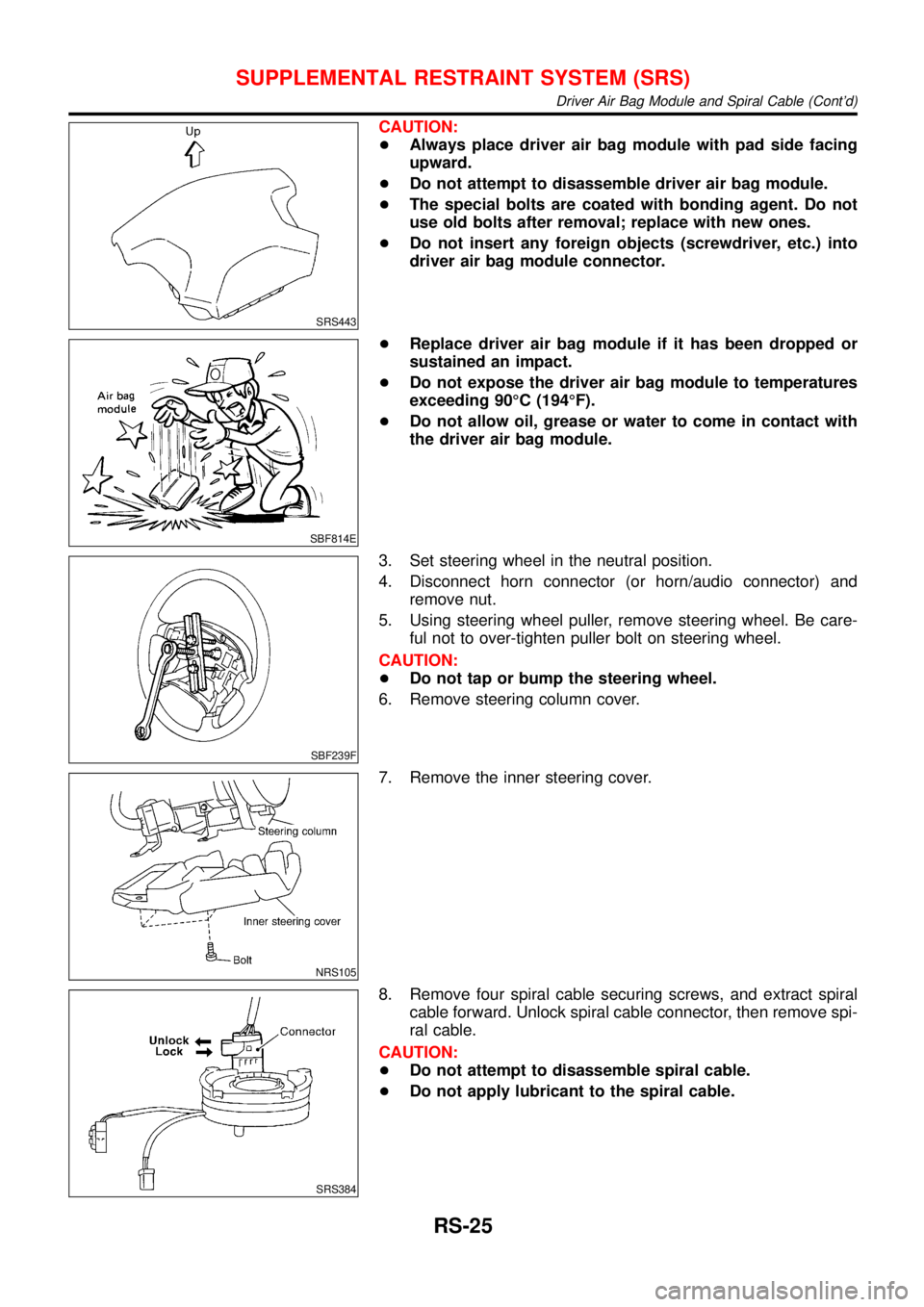
SRS443
CAUTION:
+Always place driver air bag module with pad side facing
upward.
+Do not attempt to disassemble driver air bag module.
+The special bolts are coated with bonding agent. Do not
use old bolts after removal; replace with new ones.
+Do not insert any foreign objects (screwdriver, etc.) into
driver air bag module connector.
SBF814E
+Replace driver air bag module if it has been dropped or
sustained an impact.
+Do not expose the driver air bag module to temperatures
exceeding 90°C (194°F).
+Do not allow oil, grease or water to come in contact with
the driver air bag module.
SBF239F
3. Set steering wheel in the neutral position.
4. Disconnect horn connector (or horn/audio connector) and
remove nut.
5. Using steering wheel puller, remove steering wheel. Be care-
ful not to over-tighten puller bolt on steering wheel.
CAUTION:
+Do not tap or bump the steering wheel.
6. Remove steering column cover.
NRS105
7. Remove the inner steering cover.
SRS384
8. Remove four spiral cable securing screws, and extract spiral
cable forward. Unlock spiral cable connector, then remove spi-
ral cable.
CAUTION:
+Do not attempt to disassemble spiral cable.
+Do not apply lubricant to the spiral cable.
SUPPLEMENTAL RESTRAINT SYSTEM (SRS)
Driver Air Bag Module and Spiral Cable (Cont’d)
RS-25