NISSAN ALTIMA 1996 U13 / 1.G Owners Manual
Manufacturer: NISSAN, Model Year: 1996, Model line: ALTIMA, Model: NISSAN ALTIMA 1996 U13 / 1.GPages: 183, PDF Size: 1.38 MB
Page 131 of 183
WARNING
Operating the engine with the air
cleaner off can cause you or others to
be burned. The air cleaner not only
cleans the air, it stops flame if the
engine backfires. If it isn't there, and
the engine backfires, you could be
burned. Don't drive with it off, and be
careful working on the engine with the
air cleaner off.
1) CLEANING
If your windshield is not clear after using the
windshield washer or if a wiper blade chat-
ters when running, wax or other material
may be on the blade or windshield.
Clean the outside of the windshield with a
washer solution or a mild detergent. Your
windshield is clean if beads do not form
when rinsing with clear water.
Clean each blade by wiping it with a cloth
soaked in a washer solution or a mild deter-
gent. Then rinse the blade with clear water.
If your windshield is still not clear aftercleaning the blades and using the wiper,
replace the blades.
2) REPLACEMENT
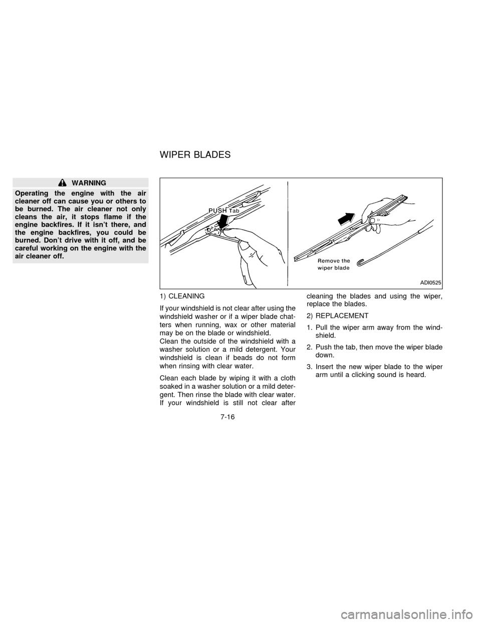
1. Pull the wiper arm away from the wind-
shield.
2. Push the tab, then move the wiper blade
down.
3. Insert the new wiper blade to the wiper
arm until a clicking sound is heard.
ADI0525
WIPER BLADES
7-16
ZX
Page 132 of 183
CAUTION
After wiper blade replacement, return
the wiper arm to its original position.
Otherwise it may be damaged when the
engine hood is opened.
Make sure the wiper blade contacts the
glass; otherwise the arm may be dam-
aged from wind pressure.
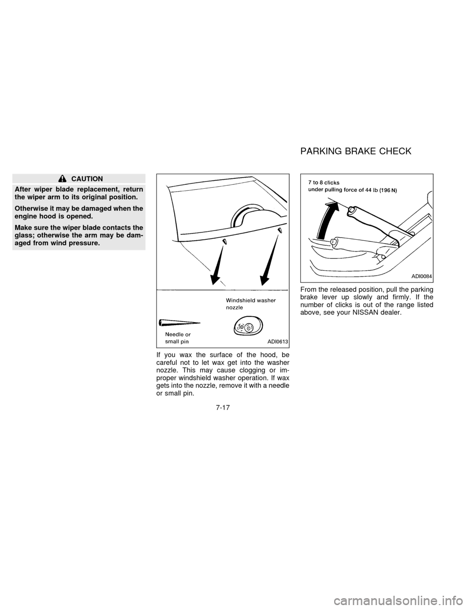
If you wax the surface of the hood, be
careful not to let wax get into the washer
nozzle. This may cause clogging or im-
proper windshield washer operation. If wax
gets into the nozzle, remove it with a needle
or small pin.From the released position, pull the parking
brake lever up slowly and firmly. If the
number of clicks is out of the range listed
above, see your NISSAN dealer.
ADI0613
ADI0084
PARKING BRAKE CHECK
7-17
ZX
Page 133 of 183
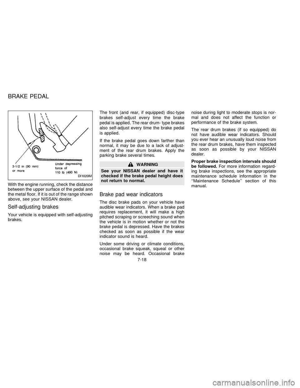
With the engine running, check the distance
between the upper surface of the pedal and
the metal floor. If it is out of the range shown
above, see your NISSAN dealer.
Self-adjusting brakes
Your vehicle is equipped with self-adjusting
brakes.The front (and rear, if equipped) disc-type
brakes self-adjust every time the brake
pedal is applied. The rear drum- type brakes
also self-adjust every time the brake pedal
is applied.
If the brake pedal goes down farther than
normal, it may be due to a lack of adjust-
ment of the rear drum brakes. Apply the
parking brake several times.
WARNING
See your NISSAN dealer and have it
checked if the brake pedal height does
not return to normal.
Brake pad wear indicators
The disc brake pads on your vehicle have
audible wear indicators. When a brake pad
requires replacement, it will make a high
pitched scraping or screeching sound when
the vehicle is in motion whether or not the
brake pedal is depressed. Have the brakes
checked as soon as possible if the wear
indicator sound is heard.
Under some driving or climate conditions,
occasional brake squeak, squeal or other
noise may be heard. Occasional brakenoise during light to moderate stops is nor-
mal and does not affect the function or
performance of the brake system.
The rear drum brakes (if so equipped) do
not have audible wear indicators. Should
you ever hear an unusually loud noise from
the rear drum brakes, have them inspected
as soon as possible by your NISSAN
dealer.
Proper brake inspection intervals should
be followed.For more information regard-
ing brake inspections, see the appropriate
maintenance schedule information in the
``Maintenance Schedule'' section of this
manual.
DI1020M
BRAKE PEDAL
7-18
ZX
Page 134 of 183

Check the brake booster function as fol-
lows:
1. With the engine off, press and release
the brake pedal several times. When
brake pedal movement (distance of
travel) remains the same from one pedal
application to the next, continue on to
next step.
2. While depressing the brake pedal, start
the engine. The pedal height should drop
a little.
3. With the brake pedal depressed, stop the
engine. Keep the pedal depressed for
about 30 seconds. The pedal height
should not change.
4. Run the engine for one minute without
depressing the brake pedal, then turn it
off. Depress the brake pedal several
times. The pedal travel distance will de-
crease gradually with each depression
as the vacuum is released from the
booster.
If the brakes do not operate properly, see
your NISSAN dealer.Press the pedal by hand and be sure the
free travel is within the limits shown above.
If free travel is out of the range shown
above, see your NISSAN dealer.
Engine compartment
If the electrical equipment does not come
on, check for an open fuse.
1. Be sure the ignition key and the headlight
switch are ``OFF''.
2. Open the engine hood.
3. Remove the fusible link cover.
4. Remove the fuse with the fuse puller.
5. If the fuse is open, replace it with a new
fuse.
ADIO528DI1313
BRAKE BOOSTER CLUTCH PEDAL FUSES
7-19
ZX
Page 135 of 183

Never use a fuse of higher amperage
rating than that specified on the fuse box
cover.
6. If a new fuse also opens, have the elec-
trical system checked and repaired by
your NISSAN dealer.
Passenger compartment
If any electrical equipment does not oper-
ate, check for an open fuse.
1. Be sure the ignition key and the headlight
switch are ``OFF''.
2. Open the fuse box cover.
3. Remove the fuse with the fuse puller.
4. If the fuse is open, replace it with a new
fuse.
Never use a fuse of higher amperage
rating than that specified on the fuse box
cover.5. If a new fuse also opens, have the elec-
trical system checked and repaired by
your NISSAN dealer.
ADI0502
7-20
ZX
Page 136 of 183
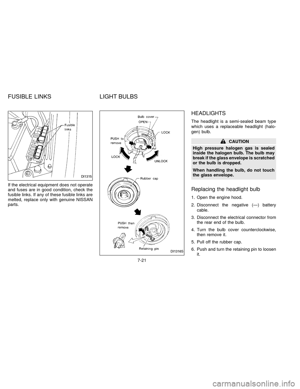
If the electrical equipment does not operate
and fuses are in good condition, check the
fusible links. If any of these fusible links are
melted, replace only with genuine NISSAN
parts.
HEADLIGHTS
The headlight is a semi-sealed beam type
which uses a replaceable headlight (halo-
gen) bulb.
CAUTION
High pressure halogen gas is sealed
inside the halogen bulb. The bulb may
break if the glass envelope is scratched
or the bulb is dropped.
When handling the bulb, do not touch
the glass envelope.
Replacing the headlight bulb
1. Open the engine hood.
2. Disconnect the negative (Ð) battery
cable.
3. Disconnect the electrical connector from
the rear end of the bulb.
4. Turn the bulb cover counterclockwise,
then remove it.
5. Pull off the rubber cap.
6. Push and turn the retaining pin to loosen
it.
DI1316S
DI1315
FUSIBLE LINKS LIGHT BULBS
7-21
ZX
Page 137 of 183
7. Remove the headlight bulb. Do not shake
or rotate the bulb when removing it.
8. Install the new bulb in the reverse order
of removal.
cBe sure the lip of the rubber cap
contacts the headlight body.
DO NOT TOUCH THE BULB.
CAUTION
cUse the same number and wattage
as originally installed:
Wattage 60/55
Bulb No. HB2
cAiming is not necessary after replac-
ing the bulb.
cDo not leave the bulb out of the
headlight reflector for a long period
of time as dust, moisture, and smoke
may enter the headlight body and
affect the performance of the head-
light.
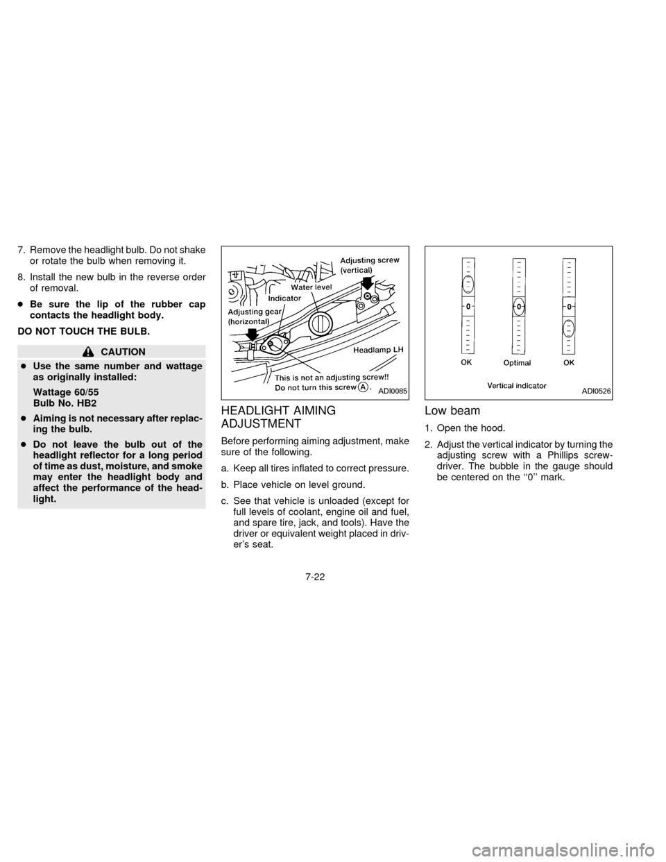
HEADLIGHT AIMING
ADJUSTMENT
Before performing aiming adjustment, make
sure of the following.
a. Keep all tires inflated to correct pressure.
b. Place vehicle on level ground.
c. See that vehicle is unloaded (except for
full levels of coolant, engine oil and fuel,
and spare tire, jack, and tools). Have the
driver or equivalent weight placed in driv-
er's seat.
Low beam
1. Open the hood.
2. Adjust the vertical indicator by turning the
adjusting screw with a Phillips screw-
driver. The bubble in the gauge should
be centered on the ``0'' mark.
ADI0085ADI0526
7-22
ZX
Page 138 of 183

3. Adjust the horizontal indicator by turning
the adjusting screw with a Phillips screw-
driver.
The inner red line with the ``0'' mark
should align with the indicator line. Never
turn screw
sAas indicated in earlier
illustration.
ADJUSTMENT AFTER
HEADLIGHT ASSEMBLY
REPLACEMENT
If the vehicle has had front body repair and
the headlight assembly has been replaced,
the aiming should be checked using the
aiming chart as shown in the illustration.
a. Adjust headlights so that main axis of
light is parallel to center line of body
and is aligned with point P shown in
the illustration.
b. Dotted lines in illustration show cen-
ter of headlight.
``H'': Horizontal center line of head-
lights
``W'': Distance between each head-
light center
``L'': Distance between the headlights
and the wall that the lights are
tested against. 7,620 mm (300.00
in)
``C'': Distance below the horizontal
center line of the light (ªHº)
used in determining the main
axis of light. 106 mm (4.17 in)
H-C=M
M = main axis of light
ADI0505
ADI0096
7-23
ZX
Page 139 of 183

Even if the horizontal indicator does not
align with the indicator line or the bubble is
not centered in the water level after aiming
by the chart, it is acceptable if they are
within the OK ranges.BULB REPLACEMENT
Item Wattage (W) Bulb No.
Headlight (Semi-sealed beam)
High/Low 60/55 HB2
Cornering light/Front park light
127/8 1157
Front park light25 168
Front turn signal light 27 1156NA
Front side marker light 3.8 194
Front fog light 55 113
Rear combination light:
Turn signal 27 1156NA
Stop/Tail 27/8 1157
Back-up 27 1156
Rear side marker light 3.8 194
License plate light 5 168
High-mounted stop light 13 912
Interior light 8
Front personal light 10
Trunk light 3.4 158
Glove box light (if so equipped) 3.4 158
1: Models with cornering light
2: Models without cornering light
7-24
ZX
Page 140 of 183

Replacement procedures
All other lights are either type A, B, C or D.
When replacing a bulb, first remove the lens
and/or cover.
ADI0527
DI1029M
7-25
ZX