manual transmission NISSAN CUBE 2012 3.G Owners Manual
[x] Cancel search | Manufacturer: NISSAN, Model Year: 2012, Model line: CUBE, Model: NISSAN CUBE 2012 3.GPages: 331, PDF Size: 2.55 MB
Page 14 of 331
0-6Illustrated table of contents
SSI0563
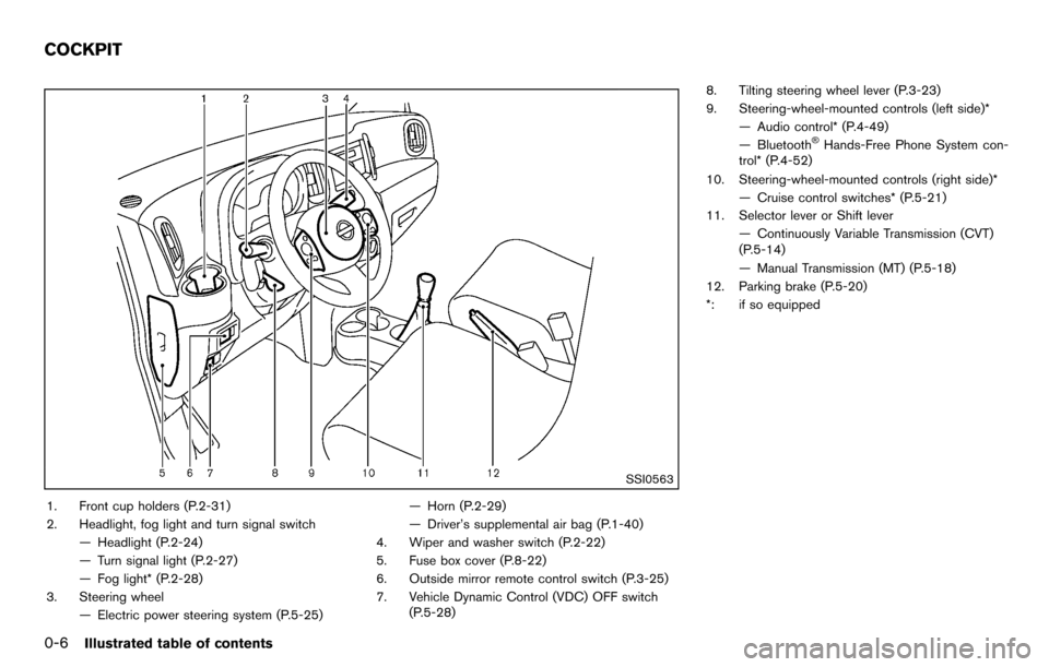
1. Front cup holders (P.2-31)
2. Headlight, fog light and turn signal switch— Headlight (P.2-24)
— Turn signal light (P.2-27)
— Fog light* (P.2-28)
3. Steering wheel — Electric power steering system (P.5-25) — Horn (P.2-29)
— Driver’s supplemental air bag (P.1-40)
4. Wiper and washer switch (P.2-22)
5. Fuse box cover (P.8-22)
6. Outside mirror remote control switch (P.3-25)
7. Vehicle Dynamic Control (VDC) OFF switch (P.5-28) 8. Tilting steering wheel lever (P.3-23)
9. Steering-wheel-mounted controls (left side)*
— Audio control* (P.4-49)
— Bluetooth
®Hands-Free Phone System con-
trol* (P.4-52)
10. Steering-wheel-mounted controls (right side)* — Cruise control switches* (P.5-21)
11. Selector lever or Shift lever
— Continuously Variable Transmission (CVT)
(P.5-14)
— Manual Transmission (MT) (P.5-18)
12. Parking brake (P.5-20)
*: if so equipped
COCKPIT
Page 17 of 331
SSI0564
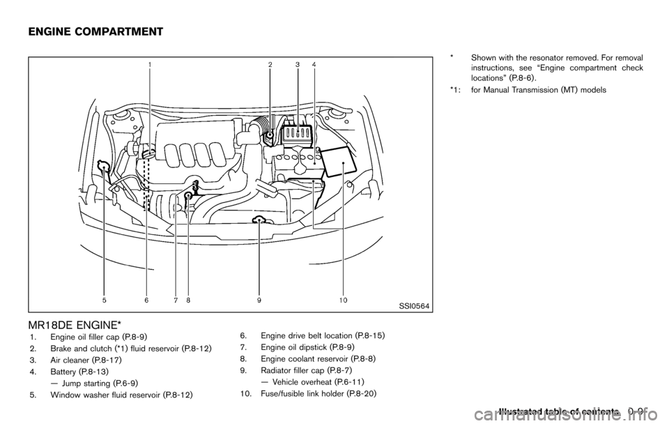
MR18DE ENGINE*1. Engine oil filler cap (P.8-9)
2. Brake and clutch (*1) fluid reservoir (P.8-12)
3. Air cleaner (P.8-17)
4. Battery (P.8-13)— Jump starting (P.6-9)
5. Window washer fluid reservoir (P.8-12) 6. Engine drive belt location (P.8-15)
7. Engine oil dipstick (P.8-9)
8. Engine coolant reservoir (P.8-8)
9. Radiator filler cap (P.8-7)
— Vehicle overheat (P.6-11)
10. Fuse/fusible link holder (P.8-20) * Shown with the resonator removed. For removal
instructions, see “Engine compartment check
locations” (P.8-6) .
*1: for Manual Transmission (MT) models
Illustrated table of contents0-9
ENGINE COMPARTMENT
Page 21 of 331
SSS0792
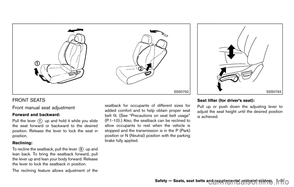
FRONT SEATS
Front manual seat adjustment
Forward and backward:
Pull the lever
*1up and hold it while you slide
the seat forward or backward to the desired
position. Release the lever to lock the seat in
position.
Reclining:
To recline the seatback, pull the lever
*2up and
lean back. To bring the seatback forward, pull
the lever up and lean your body forward. Release
the lever to lock the seatback in position.
The reclining feature allows adjustment of the seatback for occupants of different sizes for
added comfort and to help obtain proper seat
belt fit. (See “Precautions on seat belt usage”
(P.1-10) .) Also, the seatback can be reclined to
allow occupants to rest when the vehicle is
stopped and the transmission is in the P (Park)
position or N (Neutral) position with the parking
brake fully applied.
SSS0793
Seat lifter (for driver’s seat):
Pull up or push down the adjusting lever to
adjust the seat height until the desired position
is achieved.
Safety — Seats, seat belts and supplemental restraint system1-3
Page 74 of 331
2-2Instruments and controls
SSI0563
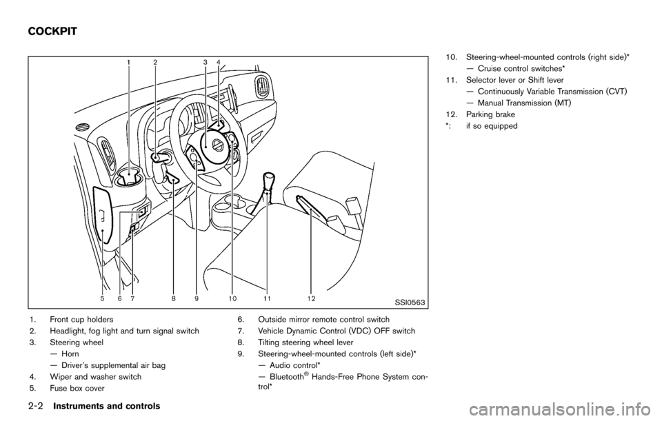
1. Front cup holders
2. Headlight, fog light and turn signal switch
3. Steering wheel— Horn
— Driver’s supplemental air bag
4. Wiper and washer switch
5. Fuse box cover 6. Outside mirror remote control switch
7. Vehicle Dynamic Control (VDC) OFF switch
8. Tilting steering wheel lever
9. Steering-wheel-mounted controls (left side)*
— Audio control*
— Bluetooth
®Hands-Free Phone System con-
trol* 10. Steering-wheel-mounted controls (right side)*
— Cruise control switches*
11. Selector lever or Shift lever
— Continuously Variable Transmission (CVT)
— Manual Transmission (MT)
12. Parking brake
*: if so equipped
COCKPIT
Page 89 of 331
High beam indicator light
This light illuminates when the headlight high
beam is on and goes out when the low beam is
selected.
Malfunction Indicator Light (MIL)
If the malfunction indicator light illuminates
steady or blinks while the engine is running, it
may indicate a potential emission control and/or
Continuously Variable Transmission (CVT) mal-
function.
The malfunction indicator light may also illumi-
nate steady if the fuel-filler cap is loose or
missing, or if the vehicle runs out of fuel. Check
to make sure the fuel-filler cap is installed and
closed tightly, and that the vehicle has at least 3
US gallons (11.4 liters) of fuel in the fuel tank.
After a few driving trips, the
light should
turn off if no other potential emission control
system malfunction exists.
If this indicator light remains on for 20 seconds
and then blinks for 10 seconds when the engine
is not running, it indicates that the vehicle is not
ready for an emission control system inspection/
maintenance test. (See “Readiness for Inspec-
tion/Maintenance (I/M) test” (P.9-19) .)
Operation:
The malfunction indicator light will illuminate in
one of two ways: .
Malfunction indicator light illuminated steady
— An emission control system and/or CVT
malfunction has been detected. Check the
fuel-filler cap if the LOOSE FUEL CAP
warning message is displayed on the twin
trip odometer. If the fuel-filler cap is loose or
missing, tighten or install the cap and
continue to drive the vehicle. The
light
should turn off after a few driving trips. If the
light does not turn off after a few driving
trips, have the vehicle inspected by a
NISSAN dealer. You do not need to have
your vehicle towed to the dealer.
. Malfunction indicator light blinking — An
engine misfire has been detected which may
damage the emission control system.
To reduce or avoid emission control system
damage:
1) Do not drive at speeds above 45 MPH
(72 km/h).
2) Avoid hard acceleration or deceleration.
3) Avoid steep uphill grades.
4) If possible, reduce the amount of cargo being hauled or towed.
The malfunction indicator light may stop
blinking and remain illuminated.
Have the vehicle inspected by a NISSAN
dealer. You do not need to have your vehicle
towed to the dealer.
CAUTION
Continued vehicle operation without
having the emission control system
and/or CVT system checked and re-
paired as necessary could lead to poor
driveability, reduced fuel economy, and
possible damage to the emission con-
trol system.
Overdrive off indicator light (if so
equipped)
The overdrive off indicator light illuminates when
the overdrive off mode is selected.
For additional information, see “Continuously
Variable Transmission (CVT)” (P.5-14) of this
manual.
Security indicator light
The light blinks when the ignition switch is in the
ACC, OFF or LOCK position. This function
indicates the security system equipped on the
vehicle is operational.
If the security system is malfunctioning, this light
will remain on while the ignition switch is in the
ON position. For additional information, see
“Security systems” (P.2-19) .
Instruments and controls2-17
Page 205 of 331
5 Starting and driving
Precautions when starting and driving ................................ 5-2Exhaust gas (carbon monoxide) ...................................... 5-2
Three-way catalyst .............................................................. 5-3
Tire Pressure Monitoring System (TPMS) .................... 5-3
Avoiding collision and rollover ......................................... 5-6
Off-road recovery ................................................................ 5-6
Rapid air pressure loss ...................................................... 5-6
Drinking alcohol/drugs and driving ................................. 5-7
Ignition switch (models without Intelligent
Key system) ........................................................................\
........ 5-8
Continuously Variable Transmission (CVT) ................... 5-8
Manual Transmission (MT) ................................................ 5-9
Key positions ........................................................................\
5-9
Push-button ignition switch (models with Intelligent
Key system) ........................................................................\
........ 5-9 Operating range for engine start function ................. 5-10
Push-button ignition switch operation ........................ 5-10
Push-button ignition switch positions ......................... 5-11
Emergency engine shut off ............................................ 5-11
Intelligent Key battery discharge .................................. 5-12
Before starting the engine ................................................... 5-12
Starting the engine ................................................................ 5-13 Models without Intelligent Key system ....................... 5-13
Models with Intelligent Key system ............................. 5-13 Driving the vehicle ................................................................. 5-14
Continuously Variable Transmission (CVT) ............. 5-14
Manual Transmission (MT) ........................................... 5-18
Parking brake ........................................................................\
.. 5-20
Cruise control (if so equipped) ......................................... 5-21 Precautions on cruise control ..................................... 5-21
Cruise control operations ............................................ 5-22
Break-in schedule ................................................................. 5-23
Increasing fuel economy ...................................................... 5-23
Parking/parking on hills ........................................................ 5-24
Electric power steering system ......................................... 5-25
Brake system ........................................................................\
.. 5-26 Braking precautions ...................................................... 5-26
Anti-lock Braking System (ABS) ............................... 5-26
Vehicle Dynamic Control (VDC) system ......................... 5-28
Cold weather driving ............................................................ 5-29
Freeing a frozen door lock ........................................... 5-29
Anti-freeze ........................................................................\
5-29
Battery ........................................................................\
....... 5-29
Draining of coolant water ............................................. 5-29
Tire equipment ................................................................ 5-30
Special winter equipment ............................................ 5-30
Driving on snow or ice ................................................. 5-30
Engine block heater (if so equipped) ....................... 5-30
Page 213 of 331
SSD0503
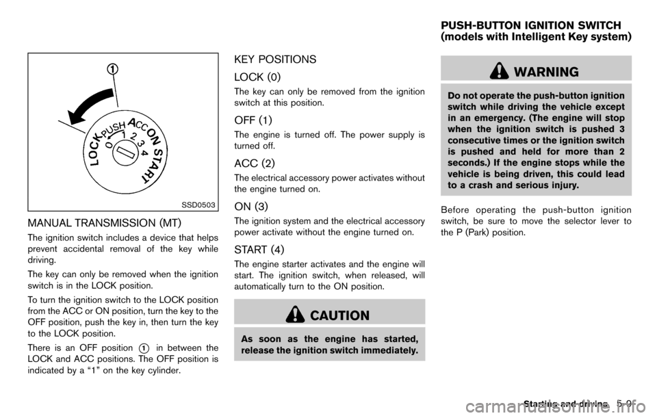
MANUAL TRANSMISSION (MT)
The ignition switch includes a device that helps
prevent accidental removal of the key while
driving.
The key can only be removed when the ignition
switch is in the LOCK position.
To turn the ignition switch to the LOCK position
from the ACC or ON position, turn the key to the
OFF position, push the key in, then turn the key
to the LOCK position.
There is an OFF position
*1in between the
LOCK and ACC positions. The OFF position is
indicated by a “1” on the key cylinder.
KEY POSITIONS
LOCK (0)
The key can only be removed from the ignition
switch at this position.
OFF (1)
The engine is turned off. The power supply is
turned off.
ACC (2)
The electrical accessory power activates without
the engine turned on.
ON (3)
The ignition system and the electrical accessory
power activate without the engine turned on.
START (4)
The engine starter activates and the engine will
start. The ignition switch, when released, will
automatically turn to the ON position.
CAUTION
As soon as the engine has started,
release the ignition switch immediately.
WARNING
Do not operate the push-button ignition
switch while driving the vehicle except
in an emergency. (The engine will stop
when the ignition switch is pushed 3
consecutive times or the ignition switch
is pushed and held for more than 2
seconds.) If the engine stops while the
vehicle is being driven, this could lead
to a crash and serious injury.
Before operating the push-button ignition
switch, be sure to move the selector lever to
the P (Park) position.
Starting and driving5-9
PUSH-BUTTON IGNITION SWITCH
(models with Intelligent Key system)
Page 217 of 331
MODELS WITHOUT INTELLIGENT KEY
SYSTEM
1. Apply the parking brake.
2.Continuously Variable Transmission
(CVT) models:
Move the selector lever to the P (Park) or N
(Neutral) position. (P is recommended.)
The starter is designed so that it does not
operate unless the selector lever is in either
of the above positions.
Manual Transmission (MT) models:
Move the shift lever to the N (Neutral)
position. Depress the clutch pedal fully to
the floor.
The starter is designed not to operate unless
the clutch pedal is fully depressed.
3. Crank the engine with your foot off the
accelerator pedal by turning the ignition
switch to START. Release the switch when
the engine starts. If the engine starts, but
fails to run, repeat the above procedure.
.If the engine is very hard to start in
extremely cold weather or when restart-
ing, depress the accelerator pedal a little
(approximately 1/3 to the floor) and hold
it and then crank the engine. Release the
accelerator pedal when the engine starts.
.If the engine is very hard to start becauseit is flooded, depress the accelerator
pedal all the way to the floor and hold it.
Crank the engine for 5 - 6 seconds. After
cranking the engine, release the accel-
erator pedal. Crank the engine with your
foot off the accelerator pedal by
turning the ignition switch to START.
Release the ignition switch when the
engine starts. If the engine starts, but fails
to run, repeat the above procedure.
CAUTION
Do not operate the starter for more
than 15 seconds at a time. If the engine
does not start, turn the ignition switch
off and wait 10 seconds before cranking
again, otherwise the starter could be
damaged.
4. Warm-up
Allow the engine to idle for at least 30
seconds after starting. Do not race the
engine while warming it up. Drive at
moderate speed for a short distance first,
especially in cold weather. In cold weather,
keep the engine running for a minimum of 2 -
3 minutes before shutting it off. Starting and stopping the engine over a short period of
time may make the vehicle more difficult to
start.
5. To stop the engine, move the selector lever to the P (Park) position (CVT model) or move
the shift lever to the N (Neutral) position (MT
model) , and turn the ignition switch to the
OFF position.
MODELS WITH INTELLIGENT KEY
SYSTEM
1. Apply the parking brake.
2. Move the selector lever to the P (Park) or N(Neutral) position. (P is recommended.)
The starter is designed not to operate unless
the selector lever is in either of the above
positions.
The Intelligent Key must be carried
when operating the ignition switch.
3. Push the ignition switch to the ON position. Depress the brake pedal and push the
ignition switch to start the engine.
To start the engine immediately, push and
release the ignition switch while depressing
the brake pedal with the ignition switch in
any position.
.If the engine is very hard to start inextremely cold weather or when restart-
ing, depress the accelerator pedal a little
Starting and driving5-13
STARTING THE ENGINE
Page 222 of 331
5-18Starting and driving
SSD0864
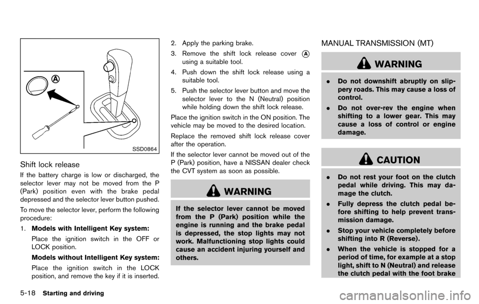
Shift lock release
If the battery charge is low or discharged, the
selector lever may not be moved from the P
(Park) position even with the brake pedal
depressed and the selector lever button pushed.
To move the selector lever, perform the following
procedure:
1.Models with Intelligent Key system:
Place the ignition switch in the OFF or
LOCK position.
Models without Intelligent Key system:
Place the ignition switch in the LOCK
position, and remove the key if it is inserted. 2. Apply the parking brake.
3. Remove the shift lock release cover
*A
using a suitable tool.
4. Push down the shift lock release using a suitable tool.
5. Push the selector lever button and move the selector lever to the N (Neutral) position
while holding down the shift lock release.
Place the ignition switch in the ON position. The
vehicle may be moved to the desired location.
Replace the removed shift lock release cover
after the operation.
If the selector lever cannot be moved out of the
P (Park) position, have a NISSAN dealer check
the CVT system as soon as possible.
WARNING
If the selector lever cannot be moved
from the P (Park) position while the
engine is running and the brake pedal
is depressed, the stop lights may not
work. Malfunctioning stop lights could
cause an accident injuring yourself and
others.
MANUAL TRANSMISSION (MT)
WARNING
. Do not downshift abruptly on slip-
pery roads. This may cause a loss of
control.
. Do not over-rev the engine when
shifting to a lower gear. This may
cause a loss of control or engine
damage.
CAUTION
.Do not rest your foot on the clutch
pedal while driving. This may da-
mage the clutch.
. Fully depress the clutch pedal be-
fore shifting to help prevent trans-
mission damage.
. Stop your vehicle completely before
shifting into R (Reverse) .
. When the vehicle is stopped for a
period of time, for example at a stop
light, shift to N (Neutral) and release
the clutch pedal with the foot brake
Page 225 of 331
SPA2110
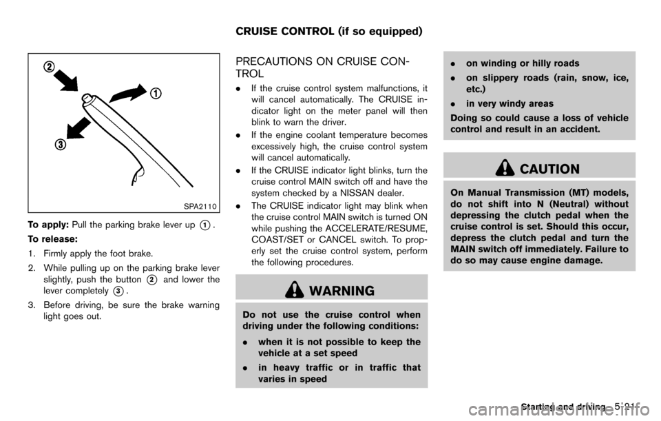
To apply:Pull the parking brake lever up*1.
To release:
1. Firmly apply the foot brake.
2. While pulling up on the parking brake lever slightly, push the button
*2and lower the
lever completely
*3.
3. Before driving, be sure the brake warning light goes out.
PRECAUTIONS ON CRUISE CON-
TROL
.If the cruise control system malfunctions, it
will cancel automatically. The CRUISE in-
dicator light on the meter panel will then
blink to warn the driver.
. If the engine coolant temperature becomes
excessively high, the cruise control system
will cancel automatically.
. If the CRUISE indicator light blinks, turn the
cruise control MAIN switch off and have the
system checked by a NISSAN dealer.
. The CRUISE indicator light may blink when
the cruise control MAIN switch is turned ON
while pushing the ACCELERATE/RESUME,
COAST/SET or CANCEL switch. To prop-
erly set the cruise control system, perform
the following procedures.
WARNING
Do not use the cruise control when
driving under the following conditions:
.when it is not possible to keep the
vehicle at a set speed
. in heavy traffic or in traffic that
varies in speed .
on winding or hilly roads
. on slippery roads (rain, snow, ice,
etc.)
. in very windy areas
Doing so could cause a loss of vehicle
control and result in an accident.
CAUTION
On Manual Transmission (MT) models,
do not shift into N (Neutral) without
depressing the clutch pedal when the
cruise control is set. Should this occur,
depress the clutch pedal and turn the
MAIN switch off immediately. Failure to
do so may cause engine damage.
Starting and driving5-21
CRUISE CONTROL (if so equipped)