ignition NISSAN GT-R 1998 Service Manual
[x] Cancel search | Manufacturer: NISSAN, Model Year: 1998, Model line: GT-R, Model: NISSAN GT-R 1998Pages: 230, PDF Size: 12.66 MB
Page 196 of 230

IGNITION KEY WARNING BUZZER AND LIGHT WARNING BUZZER
I Behind combination meter
Meter control unit Component Parts Location
J
Circuit Diagram
Meter Control Unit
InputlOutput Signal
Specifications
Terminal No.
Driver door switch signal
Signal
name
OFF Measuring condition
Ignition switch
I Measuring method Specification
Driver door switch
29
ON (Open)
OFF (Closed)
42
Approx. OV
Approx. 12V
Ignition power supply
54
55
Key-in detection switch
signal 1 OFF
ON
Lighting switch signal
Ground Approx. 12V
Remove
the ignition key.
Insert the ignition key. Approx. OV
Approx. 12V
Approx. 12V
Approx. OV
Approx. OV
I
OFF
ON Lighting
switch: 1 ST ON
OFF
-
Page 197 of 230

FRONT WIPER
Front wiper amplifier
Component Parts Location
Circuit Diagram
Front wiper motor Front wiper and washer
SW
Washer motor
---------------- HI
EL-17040
Front Wiper InpWOutput Signal Specifications
Terminal No.
Signal name 1 Measuring condition. I
Wiper motor position detection
signal
1 Specification
Wiper switch: LO position
Ignition switch
(Reference)
I
Operation
Wiper motor LO signal
4 Wiper motor HI signal
Wiper switch
6
ON
OFF
.
Lo
7 1 Washer operation detection signal I ON
8 I Ignition power supply I ON I - I Approx. 12V
Approx. 12V
ADDIOX. OV
-
Wiper switch
I
Washer motor is in operation. I I
I - Ground
Approx.
OV
I Washer motor is not in operation. OFF
HI
. .
Approx. OV
ON
Approx.
12V
Approx. 12V
Approx. OV
Page 199 of 230

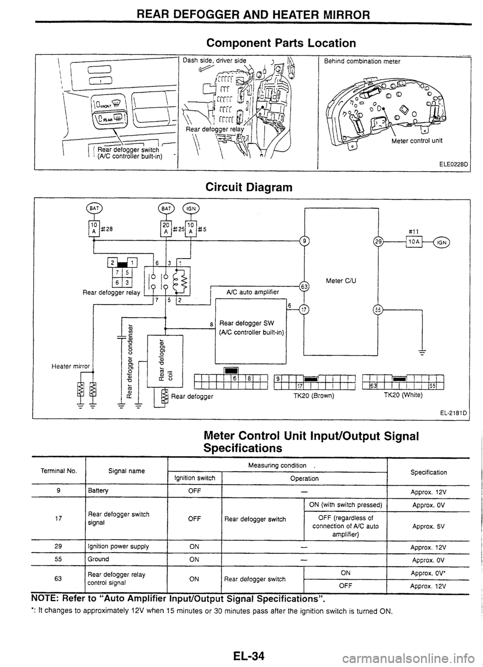
REAR DEFOGGER AND HEATER MIRROR
Component
Parts Location
-- Behind combination meter
Circuit Diagram
Heater
10 A g28 81 1
Meter CIU
Rear defogger relay AIC auto ampl~f~er
. 0
z i 8 Rear defogger SW a (AC controller built-m)
mirror
u
Rear defogger TK20 (Brown) TK20 (White)
EL-2181 D
Meter Control Unit InputlOutput Signal
S~ecif ications
': It changes to approximately 12V when 15 minutes or 30 minutes pass after the ignition switch is turned ON.
Terminal No.
9
17
29
55
63
NOTE: Refer to "Auto Amplifier InputlOutput Signal Specifications".
Signal name
Battery
Rear defogger switch
signal
Ignition power supply
Ground
Rear defogger relay
control signal Specification
Approx.
12V
Approx. OV
Approx. 5V
Approx. 12V
Approx. OV
Approx. OV*
Approx. 12V
Measuring condition .
Ignition switch OFF
OFF ON
ON
ON Operation
-
Rear
defogger switch ON (with switch
pressed)
OFF (regardless of
connection of AIC auto
amplifier)
-
-
Rear defogger switch ON OFF
Page 200 of 230

WIPER DEICER
Component
Parts Location
Wiper deicer switch I
/ I Wiper deicer switch
Circuit Diagram
m
Wiper deicer relay
Wiper deicer Wiper deicer
SW (Timer
built-in) lighting
Wiper
Deicer Switch InputlOutput Signal
Specifications
Terminal No. Signal name
Indicator power supply Measuring
condition .
Ignition switch I Operation Specification
Wiper deicer switch
2
3
OFF
ON
4
- Approx. OV
Approx. 12V
lllumination ground
Ground
5
1 Approx. 12V lgn~tion power supply
6
OFF
ON
Wiper deicer relay control
signal
I ON 1 Wiper deicer switch
ON
*: When
the wiper deicer is activated (approx. 15 minutes).
Illumination power supply
-- -
- - - - - -
ON
OFF
- Approx. OV
Approx. OV
Approx. OV'
Approx. 12V
OFF Lighting
switch: 1ST -- - Approx. 12V
Page 202 of 230
![NISSAN GT-R 1998 Service Manual
ENGINE MECHANICAL I RB~ODE (UB) ]
STANDARD AND REPAIR LIMIT
Firing order I 1-5-3-6-2-4
Compression pressure
MPa
(kg/cm2)/rpm
Distortion limit mm
- - -- --- - Ignition advance device
Electr NISSAN GT-R 1998 Service Manual
ENGINE MECHANICAL I RB~ODE (UB) ]
STANDARD AND REPAIR LIMIT
Firing order I 1-5-3-6-2-4
Compression pressure
MPa
(kg/cm2)/rpm
Distortion limit mm
- - -- --- - Ignition advance device
Electr](/img/5/57354/w960_57354-201.png)
ENGINE MECHANICAL I RB~ODE (UB) ]
STANDARD AND REPAIR LIMIT
Firing order I 1-5-3-6-2-4
Compression pressure
MPa
(kg/cm2)/rpm
Distortion limit mm
- - -- --- - Ignition advance device
Electronically-controlled ignition advance
Engine
oil capacity
e
Spark plug standard
Limit
. Limit
of variation between cylinders
Intake manifold
Intake manifold collector
Exhaust manifold
Cylinder head
Cvlinder block
lgnition timing (during no feed back control) 1.23
(1 2%)/300
0.93 (9.5)1300
0.1 (1.0)/300
0.1 0.1
0.3
0.2
0.1
Without filter
With filter
MakerlTypeISpark
plug gap mm
Engine idling speed
W'
Idle base speed (during no feed back control)
rPm
Density of
COIHC at idling speed
Wppm Approx.
3.8
Approx. 4.2
NG WPFR5G-11 11.0
- 1
-1
650-.50
(N or P position for
A/T)
600 (N or P position for AlT)
Less than O.l/Less than 50
I New I Used I Limit
Valve
clearance
(INTIEXH)
mm
Deflection
amount of accessory V-belt
Measured with tension gauge
N (kg) Hot
engine
.
Cold engine (at ambient temperature)
Measured by pushing at 98 N (10 kg)
mm 0.36+0.062/0.53+0.062
0.31 1~,0.04/0.50i0.04
Fuel tank capacity
e
Engine coolant total capacity [with reservoir tank (max. level)] e
Thermostat opening temperature [start to open - full open]
"C
Radiator cap opening pressure
MPa (kg/cm2) Approx.
65
Approx. 9.4 82 - 95
0.06
- 0.1 0 (0.6 - 1 .O)
A/C compressor belt
Power
steering pump belt
Fan belt
Power steering pump belt
1 8-10 1 10-12 1 16
667
- 755
(68
- 77)
A/C compressor belt 1 6-8 1 7-9 / 12
Fan belt
1 3-5 1 4-6 1 7.5
559 - 637
(57
- 65)
SEC.117 Power steering
Fan belt pump be1 t
284 (29)
Page 203 of 230

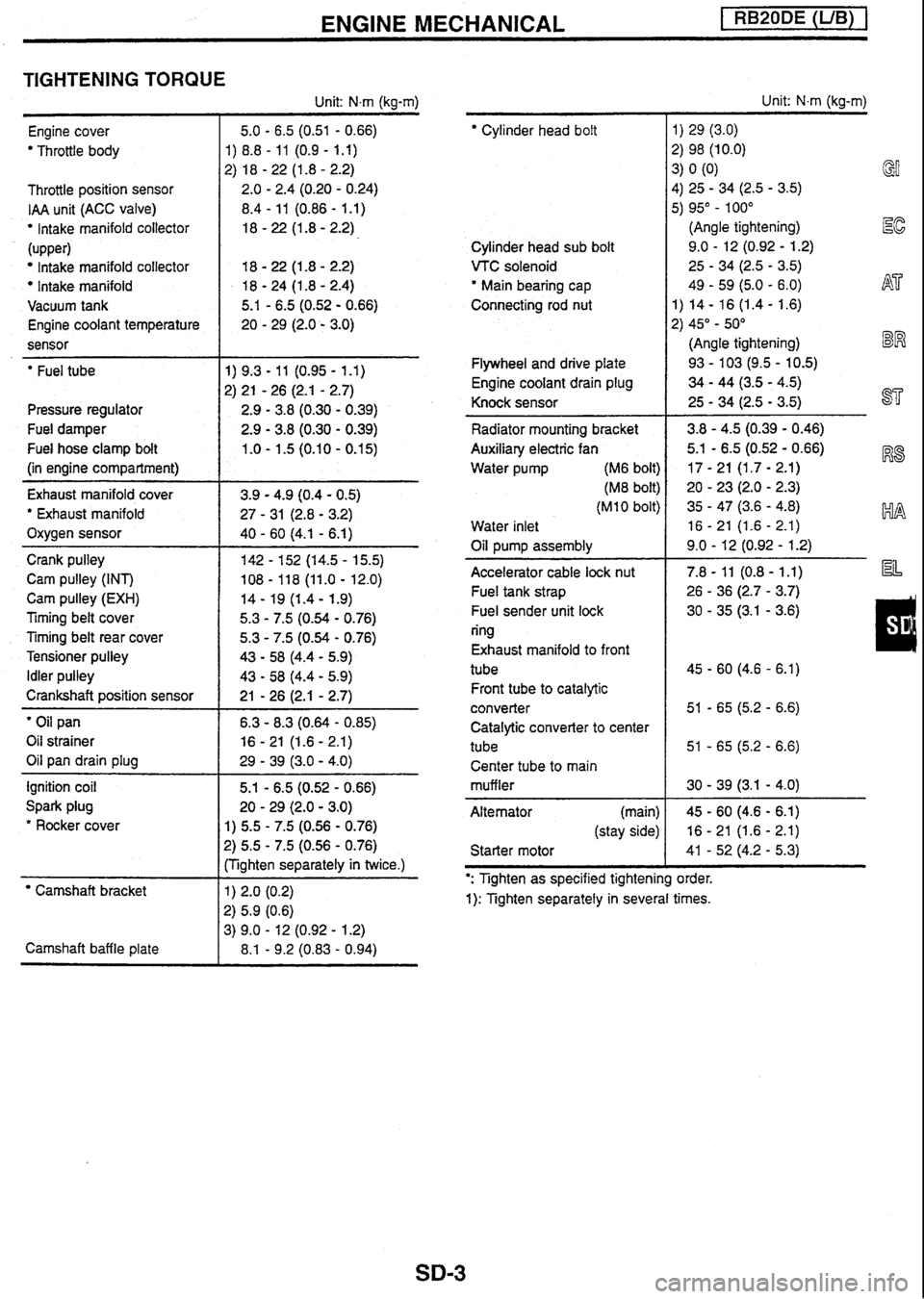
ENGINE MECHANICAL [ RB20DE (UB) 1
TIGHTENING TORQUE
Unit: N.m (kg-m)
Engine cover
Throttle body
Throttle position sensor
IAA unit (ACC valve)
lntake manifold collector
(upper)
Intake manifold collector
Intake manifold
Vacuum tank
Engine coolant temperature
sensor
- --
' Fuel tube
Pressure regulator
Fuel damper
Fuel hose clamp bolt
(in engine compartment)
Exhaust manifold cover
' Exhaust manifold
Oxygen sensor
Crank pulley
Cam pulley (INT)
Cam pulley
(EXH)
Timing belt cover
Timing belt rear cover
Tensioner pulley
Idler pulley
Crankshaft position sensor
' Oil pan
Oil strainer
Oil pan drain plug
ignition coil
Spark plug
* Rocker cover
Camshaft bracket
Camshaft baffle plate 5.1
- 6.5 (0.52 - 0.66)
20
- 29 (2.0 - 3.0)
1) 5.5 - 7.5 (0.56 - 0.76)
?) 5.5 - 7.5 (0.56 - 0.76)
:Tighten separately in twice.)
Cylinder head bolt
Cylinder head sub bolt
VTC solenoid
' Main bearing cap
Connecting rod nut
Flywheel and drive plate
Engine coolant drain plug
Knock sensor
Radiator mounting bracket
Auxiliary electric fan
Water pump (M6 bolt)
(M8 bolt)
(MI 0 bolt)
Water inlet
Oil pump assembly
Accelerator cable
lock nut
Fuel tank strap
Fuel sender unit lock
ring
Exhaust manifold to front
tube Front tube to catalytic
converter Catalytic converter to cent
tube Center tube to main
muffler
Alternator (main)
(stay side)
Starter motor Unit:
N-m (kg-m)
1)
29 (3.0)
2) 98 (10.0)
3)
0
(0)
4) 25
- 34 (2.5 - 3.5) GI
5) 95" - 100"
(Angle tightening)
Ec
9.0 - 12 (0.92 - 1.2)
25
- 34 (2.5 - 3.5)
49
- 59 (5.0 - 6.0) h$7'
1) 14 - 16 (1.4 - 1.6)
2) 45"
- 50"
(Angle tightening)
BW
93 - 103 (9.5 - 10.5)
34 - 44 (3.5 - 4.5)
25
- 34 (2.5 - 3.5) ST
': Tighten as specified tightening order.
1): Tighten separately in several times.
Page 204 of 230

ENGINE MECHANICAL
STANDARD AND REPAIR LIMIT
Firing order
Compression pressure
MPa (kg/cm2)/rpm
-
Intake manifold
Intake manifold collector
--- - Standard Limit
Limit of variation between
cylinders
0.1
0.1
Distortion limit mm
Engine oil capacity
P
Spark plug
Deflection amount of accessory
V-belt Power steering pump
belt
I
- -- - - 1.26 (1 2.8)/300
0.96 (9.8)/300
0.1
(1 .OY300
Measured with tension gauge Exhaust
manifold
Cylinder head
Cylinder block
Without filter
With filter
MakerKype/Spark
plug gap
mrn
I "
650.-50 (N or P position for CVT)
600 (N or P position for AIT)
Less than O.l/Less than 50
15U600
0.36~0.06210.53~0.062
0.31 -.0.04/0.50~0.04
Approx. 65
Approx. 9.4
82 - 95
0.06 - 0.10 (0.6 - 1 .O)
"
Engine idling speed rpm
Idle base speed (during no feed back control)
rpm
Density of
COIHC at idling speed
%/ppm
Ignition timing (during no feed back control)
BTDCO/rpm
I NC compressor err
0.3
0.2
0.1
Approx. 3.8
Approx. 4.2
NGWPFR5G-11/1.0
- 1.1
lanition
advance device
1
Valve clearance (INTIEXH) mm
(kg)
/ Fan belt Electronicallv-controlled
ianition
advance
Hot engine
Cold engine (at ambient temperature)
I power steerina DU~D belt 1 8-10
Fuel tank capacity
Q
Engine
coolant total capacity [with reservoir tank (max. level)] e
Thermostat opening temperature [start to open - full open] OC
Radiator cap opening pressure
MPa (kg/crn2)
,
I Fan belt 1 3-5
Measured
by pushing at 98
N (10 kg)
mm
I SEC.! I7 Power steering I
*I I 1
AK compressor belt 1 6-8
Fan belt pump beit
Used 1 Limit
Page 205 of 230

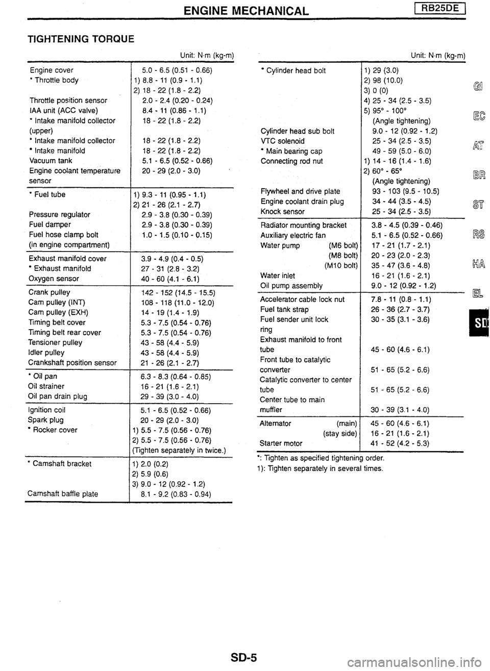
ENGINE MECHANICAL
TIGHTENING TORQUE
Engine cover
' Throttle body
Throttle position sensor
IAA unit (ACC valve)
' Intake manifold collector
(upper)
' Intake manifold collector
Intake manifold
Vacuum tank
Engine coolant temperature
sensor
' Fuel tube
Pressure regulator
Fuel damper
Fuel hose clamp bolt
(in engine compartment)
Exhaust manifold cover
Exhaust manifold
Oxygen sensor
Crank pulley
Cam pulley (INT)
Cam pulley
(EXH)
Timing belt cover
Ttming belt rear cover
Tensioner pulley
Idler pulley
Crankshaft position sensor
' Oil pan
Oil strainer
Oil pan drain plug
Ignition coil
Spark plug
Rocker cover
* Camshaft bracket
Camshaft baffle plate Unit:
Nm (kg-m)
5.0
- 6.5 (0.51 - 0.66)
1) 8.8
- 11 (0.9 - 1.1)
2) 18
- 22 (1.8 - 2.2)
2.0
- 2.4 (0.20 - 0.24)
8.4
- 11 (0.86 - 1 .I)
18
- 22 (1.8 - 2.2)
5.1
- 6.5 (0.52 - 0.66)
20
- 29 (2.0 - 3.0)
1) 5.5 - 7.5 (0.56 - 0.76)
2) 5.5 - 7.5 (0.56 - 0.76)
:Tighten separately in twice.)
Cylinder head bolt
Cylinder head sub bolt
VTC solenoid
Main bearing cap
Connecting rod nut
Flywheel and drive plate
Engine coolant drain plug
Knock sensor
Radiator mounting bracket
Auxiliary electric fan
Water pump
(M6 bolt)
(M8 bolt)
(M 1 0 bolt)
Water inlet
Oil pump assembly
-
Accelerator cable lock nut
Fuel tank strap
Fuel sender unit lock
ring
Exhaust manifold to front
tube
Front tube to catalytic
converter
Catalytic converter to center
tube Center tube to main
muffler
Alternator (main)
(stay side)
Starter motor Unit:
N.m (kg-m)
1) 29 (3.0)
2) 98 (10.0) 3) 0 (0)
@
4)
25 - 34 (2.5 - 3.5)
5) 95" - 100"
(Angle tightening)
E
9.0 - 12 (0.92 - 1.2)
25
- 34 (2.5 - 3.5) j$? 49 - 59 (5.0 - 6.0)
1) 14- 16
(1.4- 1.6)
2) 60"
- 65" BR
(Angle tightening)
93
- 103 (9.5 - 10.5)
34 - 44 (3.5 - 4.5)
25
- 34 (2.5 - 3.5) a=
': Tighten as specified tightening order.
1): Tighten separately in several times.
Page 206 of 230

ENGINE MECHANICAL
STANDARD AND REPAIR LIMIT
Distortion limit mm
- - Intake manifold
Intake manifold collector
1 -5-3-6-2-4
1.20 (1
2.2)/300
0.90 (9.2)/300
0.1 (1.0)/300
Firing order
-- - 0.1
0.1
- -- - ( Cylinder block 0.1
Compression
pressure
MPa
(kg/cm2)/rpm
Exhaust manifold
Cvlinder head
Engine oil capacity Standard
Limit
-
Limit of variation between cylinders
0.3
0.2
- - -- - Spark plug I ~akerfl~~e/~~ark plug gap mm r NGKPFRGG-11/1.0 - 1.1
Without
filter
'with
filter
ignition advance device
I Electronically-controlled ignition advance
Approx.
3.9
Aoorox.
4.3
Engine idling speed
rPm
Idle
base speed (during no feed back control)
Pm
650-e50
(N or P position for
A/T)
600 (N or P position for AQ
Density of COIHC at idling speed
Wppm
Ignition timing (during no feed back control)
BTDCO/rpm Less
thanbl~ess than 50
15dY600
Valve clearance
(INT/EXH) mm
Deflection amount of accessory V-belt Hot
engine
Cold engine (at ambient temperature)
Measured
with tension gauge
(kg)
I
SEC.117 Power steering
Fan belt pump belt
0.36+0.062/0.53i0.062
0.3
1 20 .04/0.50a0.04
Fuel tank capacity
4
Engine coolant total capacity [with reservoir tank (max. level)] t
Thermostat opening temperature [start to open - full open]
OC
Radiator cap opening pressure
MPa (kg/cm2)
Power steering pump belt
Measured by pushing at 98
N (1 0 kg)
mm Approx.
65
Approx. 9.4
82
- 95
0.06
- 0.1 0 (0.6 - 1 .O)
New 1 Used 1 Limit
AfC
compressor belt
Fan belt
,
667 - 755
(68
- 77)
Power steering pump belt
' AfC compressor belt
Fan belt
559 - 637 284 (29)
(57 - 65)
667
- 755
(68
- 77)
667
- 755
(68
- 77)
559 - 637 284 (29)
(57 - 65)
559 - 637 284 (29) (57 - 65)
8-
10
6-8
3 - 5
- 10 - 12 16
7-9 12
4
- 6 7.5
Page 207 of 230

ENGINE MECHANICAL pEZBq
TIGHTENING TORQUE
Engine cover
' Throttle body
Throttle position sensor
IAA unit
(ACC valve)
' Intake manifold collector
* Intake manifold
Engine coolant temperature
sensor
' Fuel tube
Pressure regulator
Fuel damper
Fuel hose clamp bolt
(in engine compartment)
Turbocharger Oil tube
Water tube (block side)
(turbocharger side)
Oxygen sensor
Exhaust manifold cover
' Exhaust manifold
Crank pulley
Cam pulley (INT)
Cam pulley
(EXH)
Timing belt cover
Timing belt rear cover
Tensioner pulley
Idler pulley
Crankshaft position sensor
' Oil pan
Oil strainer
Oil pan drain plug
Ignition coil
Spark plug
' Rocker cover
' Camshaft bracket
Camshaft baffle plate Unit:
N.m (kg-m)
5.0
- 6.5 (0.51 - 0.66)
1)
8.8
- 11 (0.9 - 1.1)
2)
18
- 22 (1 -8 - 2.2)
2.0
- 2.4 (0.20 - 0.24)
8.4
- 11 (0.86 - 1.1)
18
- 22 (1.8 - 2.2)
18
- 22 (1 -8 - 2.2)
20
- 29 (2.0 - 3.0)
5.1
- 6.5 (0.52 - 0.66)
20
- 29 (2.0 - 3.0)
1) 5.5
- 7.5 (0.56 - 0.76)
2) 5.5 - 7.5 (0.56 - 0.76)
(Tighten separately in twice.)
' Cylinder head boit
Cylinder head sub bolt
VTC solenoid
" Main bearing cap
Connecting rod
nut
Oil jet
Flywheel and drive plate
Engine coolant drain plug
Knock sensor
Radiator mounting bracket
Auxiliary electric fan
Water pump (M6 bolt)
(M8 bolt)
(MI
0 bolt)
Water inlet
Oil pump assembly
Accelerator cable lock nut
Fuel tank strap
Fuel sender unit lock
ring
Exhaust manifold to front
tube
Front tube to catalytic
converter
Catalytic converter to center
tube
Center tube to main
muffler
Alternator (main)
(stay side)
Starter motor Unit:
N.m (kg-m)
1) 29 (3.0)
2) 98 (10.0)
3) 0 (0)
4) 25 - 34 (2.5 - 3.5)
5) 95"
- 100"
(Angle tightening)
I%
9.0 - 12 (0.92 - 1.2)
25
- 34 (2.5 - 3.5)
49
- 59 (5.0 - 6.0) AT
1) 14 - 16 (1.4 - 1.6)
2) 60" - 65"
(Angle tightening) BR
30 - 40 (3.1 - 4.1)
93
- 103 (9.5 - 10.5)
34 - 44 (3.5 - 4.5) ST
25 - 34 (2.5 - 3.5)
3.8
- 4.5 (0.39 - 0.46) I%$
5.1 - 6.5 (0.52 - 0.66)
17
- 21 (1.7 - 2.1)
20
- 23 (2.0 - 2.3) kIA
35 - 47 (3.6 - 4.8)
16
- 21 (1.6 - 2.1)
9.0
- 12 (0.92 - 1.2) a=
': Tighten as specified tightening order.
1): Tighten separately in several times.