ignition NISSAN GT-R 1998 Owners Manual
[x] Cancel search | Manufacturer: NISSAN, Model Year: 1998, Model line: GT-R, Model: NISSAN GT-R 1998Pages: 230, PDF Size: 12.66 MB
Page 178 of 230

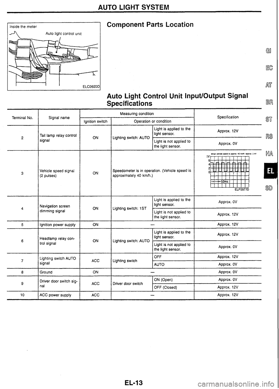
AUTO LIGHT SYSTEM
Component
Parts Location Inside the meter
-4 Auto light control unit
Auto Light Control Unit InputlOutput Signal
Specifications
Terminal No. Measuring
condition
Operation or condition
I
Signal name Specification
Ignition switch
I Light is applied to the I Approx. 12V
liaht sensor.
Tail lamp relay control
signal
Speedometer is in operation. (Vehicle speed is
approximately 40
kmlh.)
Lighting switch: AUTO
Vehicle speed signal (2 pulses)
Light is applied to the
liaht
sensor.
I
4
Light is not applied to
the light sensor.
Approx. OV
Approx.
OV
Navigation screen
dimming signal Liahtina
switch: 1 ST
- I I
I
Light is not applied to
the light sensor.
ignition power supply Approx. 12V
I - I
I Light
is applied to the I Approx. 12V
liaht sensor. Approx. 12V
Headlamp
relay con-
trol signal Lighting
switch: AUTO
Lighting switch AUTO
signal Lighting switch
ACC -
Light is not applied to
the light sensor.
Ground Approx.
OV
OFF
AUTO Approx. 12V
Approx. OV
Driver door switch sig-
n
al
ACC Approx.
OV
Approx.
OV
Approx. 12V
-
ACC power supply Driver
door switch
ACC ON
(Open)
OFF (Closed)
- I Approx. 12V
Page 179 of 230

AUTO LIGHT SYSTEM
Circuit Diagram
Xenon
headlamp
relay
To clearance
lamp and
tail lamp
I---- I : High-voltage parts ----- EL-2163D
Trouble Diagnoses
SYMPTOM CHART
Symptom I Possible cause
I a Faulty auto light control unit power supply or ground harnesi
I Faulty auto light control unit
When outside
is dark, neither small lamps nor headlamps
tum
ON
by
auto light operation. [Lighting switch
(1ST
and 2ND)
is normal.]
When outside is dark, small lamps turn ON but headlamps do not turn
Faulty lighting switch to auto light control unit harness
ON by auto light operation. [Lighting switch (1 ST and 2ND) is normal.] Faulty auto light control unit
0 Faulty lighting switch Faulty lighting switch to auto light control unit harness a Faulty lighting switch ground harness
When outside is dark, headlamps turn ON but small lamps do not turn
ON by auto light operation. [Lighting switch
(1ST
and 2ND) is normal.]
Faulty lighting switch to auto light control unit hamess Faulty auto light control unit
a Neither headlamps nor small lamps turn OFF when the driver door is
opened with the ignition switch at ACC. a Headlamps and small lamps turn OFF when the ignition switch is
turned to ACC with the driver door closed.
0 While the vehicle is driven at night, headlamps go off momentarily
~~- - - pp a Faulty door switch a Faulty door switch to auto light control unit harness a Faulty door switch ground harness 0 Faulty auto light control unit
when it passes under street lamps.
0 While the vehicle is driven in the early morning or evening, headlamps
turn ON momentarily when it passes under an overpass or through a Faulty speedometer to auto light control unit harness a Faulty auto light control unit
building shadows.
During the day, neither small lamps nor headlamps turn OFF. During the day, headlamps tum OFF but small lamps do not turn OFF. a Faulty auto light control unit
Page 182 of 230

IGNITION KEY-OPERATED ILLUMINATION SYSTEM
Behind combination meter Component Parts Location
Meter control unit
Circuit Diagram
7, . .
& Driver door lock detection switch
T
2 1 r Passenger door SW Rear RH door SW 326
' a
Rear LH door SW
3 - -
Room lamp
IGN SW illumination
TK24 (Brown) TK20 (Brown) TK20 (White) EL-2 178D I 1 J
Meter Control Unit Input/Output Signal
Terminal No.
Specifications I I
Specification
Approx.
OV
Approx. 12V
Approx. OV
Approx. 5V
Approx. 12V
Approx. OV
Approx. 12V
Approx. 12V
Approx. OV
Approx. 12V
Approx. OV
Approx. OV
Approx. 12V
Approx. OV'
Approx. 12V
Measuring condition
Signal name Ignition
Operation or condition
switch
Driver door switch ON (Open)
OFF Driver door switch
signal OFF (Closed)
Driver door lock
sig-
Door is unlocked. (Switch ON)
nal OFF
Door is locked. (Switch OFF)
Battery OFF
-
Open a door. (ON)
Door switch signal
OFF
Close all the doors. (OFF)
Ignition power supply ON
-
Key-in detection Remove
the ignition key.
switch signal OFF
Insert the ignition key.
Ground ON
-
OFF Room lamp switch:
Insert the ignition key. Each door switch
Room lamp, ignition Neutral position ON
(Open)
OFF (Closed)
switch illumination
Remove the ignition key from the
signal
- lamp switch: Close all the doors. key cylinder.
Neutral position
Turn the ignition switch ON.
Page 186 of 230

COMBINATION METER
System Description
Speedometer, tachometer, odoltrip meter, fuel gauge, and
water temperature gauge are integrally controlled by the con-
trol circuit in the meter control unit.
Diagnosis function has odoltrip meter segment check, low fuel @
warning lamp check, and continuity check in the meter control
circuit and the meters (speedometer, tachometer, fuel gauge,
and water temperature gauge).
Component Parts Location
Combination meter ABS unit
ID Transfer (4WD) I H side of trunk room
I -unit connector I
/I Diagnosis Function
meter is displayed, turn the ignition switch ACC or
down the odoltrip meter switch, turn the ignition switch
/
ON.
3. Verify that 0000.0 km is displayed on the trip meter.
4. Press the odoltrip meter switch 3 times within 5 seconds.
5. All the odoltrip meter segments light up along with low fuel
warning lamp.
EL-21
SEGMENT CHECK AND LOW FUEL WARNING LAMP
CHECK
Page 187 of 230

COMBINATION METER
Diagnosis Function
(Cont'd)
METER CIRCUIT CHECK
After the segment check, press the odohrip meter switch to
verify that meters operate as shown below. (Low fuel warning
lamp goes off at this point.)
i
ELF0967D I It takes 1 minute for the meters to become stable.
DIAGNOSIS FUNCTION CANCELLATION
Turn the ignition switch ACC or OFF.
Meter-related Circuit Diagram
I I TO oil pressure W.L
Page 188 of 230

COMBINATION METER
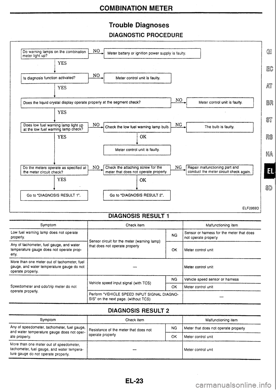
Trouble
Diagnoses
DIAGNOSTIC PROCEDURE
I YES
Meter control unit is faulty.
Meter battery or ignition power supply is faulty.
DO
warning
lamps
on
the
meter light
up?
. No .
at the low fuel warning lamp check? The bulb
is faulty.
t
Meter control unit is faulty. I
Does the liquid crystal display operate properly at the segment check? NO
Check the attaching screw for the ' NG *F3epair malfunct~oning part and
the meter circuit check? meter that
does not operate properly. * conduct the meter circuit check again.
OK
Meter control unit is faulty.
YES
DIAGNOSIS RESULT 1
4
Symptom I Check item I Malfunctioning item
Go
to "DIAGNOSIS RESULT
1".
Low fuel warning lamp does not operate
properly. Go to
"DIAGNOSIS RESULT
2".
Any of tachometer, fuel gauge, and water
temperature gauge does not operate prop-
erly.
More than one meter out of tachometer, fuel
gauge, and water temperature gauge do not
operate properly.
Speedometer and
odohrip meter do not
operate properly. Sensor
or harness for the meter that does
Sensor circuit for the meter (warning lamp)
1 1: 1 not operate properiy
1 that does not operate properly
~ Meter control unit
Meter control unit
DIAGNOSIS RESULT 2
Symptom
Any of speedometer, tachometer, fuel gauge,
and water temperature gauge does not oper-
ate properly. Vehicle
speed sensor or harness
Meter control unit
-
Vehicle speed input signal (with TCS)
Check item
I Malfunctioning item
NG
OK
Perform "VEHICLE SPEED INPUT SIGNAL
DIAGNO-
SIS"
on the next page. (without TCS)
More than one meter out of speedometer,
tachometer, fuel gauge, and water tempera-
ture gauge
do not operate properly. Resistance
of the meter that does not
operate properly
Meter control unit
NG
OK
- -
Meter that does not operate properly
Meter control unit
Page 189 of 230

COMBINATION METER
Trouble Diagnoses (Cont'd)
VEHICLE SPEED INPUT SIGNAL DIAGNOSIS
I Connector
WARNING LAMP CHECK Does ABS warning lamp remain ON with
ignition switch ON?
ABS I
Perform ABS self-diagnosis
and check faulty circuit.
Refer to
BR section ("ABS
SYSTEMn).
Continuity exists.
Terminal No. 19 and ground:
No continuity
. -- I I
HARNESS CHECK ' Disconnect ABS control unit connector
(TK24)
and meter connector (TK20
Brown).
Terminals No. 19 - 24:
OK
El f
Meter control unit connector on vehicle
NG+'
I - = 'ELF0970D
El
@EM
Meter control unit connector on vehicle rn
rm-1 ffee
1
L / - - -
ELFo971D -
ABS control unit to meter
harness is faulty.
Meter control unit
is faulty. VEHICLE SPEED INPUT SIGNAL
CHECK 1 Connect meter connector (TK20 Brown). Terminal No. 19 and around:
'2
" Approx. 9V
OK
r9 v
VEHICLE SPEED INPUT SIGNAL
CHECK 2 Connect ABS control unit connector
(TK24).
Start the engine and drive the vehicle. Terminal No. 19 and ground:
Specification
Refer to "Combination Meter InpuffOutput
Signal Specificationsn on the next page.
OK
Meter control unit is faulty.
5' Pelform ABS self-diagnosis and check faulty circuit.
Refer to BR section ("ABS
SYSTEMn).
Page 190 of 230

COMBINATION METER
Combination Meter
InputlOutput Signal
Specifications
Terminal No. Measuring condition
Signal name
Ignition switch Operation or condition
Disconnect ECM connector. Approx.
8 - 10V
At 2.000 rprn: Approx. 3.OV
IVI
15
10
5 0
ELF0973D
Tachometer drive
signal
Engine is idling or running at
!,000 rpm. RB25DET
At ~dling: Approx. 7.2V At 2.000 rprn: Approx. 72V
(VI
(VI ST
15 I5 10 10
5 5
0 0
RS
ELF0974D RA
Refer to "Component Parts Inspection" (EL-27).
Approx. 12V I
-uel gauge signal
OFF With TCS
Vehicle speed: Approx. 40 km
(VI
15 10 5 0 -5 -1 0 -1 5
A Veh~cle Speed Approx 60 kmh
Body
lrounc
Speedometer is in operation.
Vehicle speed is approx.
10 kmh.)
Vehicle speed is approx.
i0 kmh.)
e speed
inpi
Without
TCS Vehcle speed: Approx. 40 k
IV!
15 10 5 0
h Vehicle speed: Approx. 60 kmh (V) 15 10
5
0
ELF0376D
-
-
;peedometer is not in opera-
on.
hermal
transmitte
iignal Refer
to "Component Parts Inspection"
(EL-27)
gnition power sup
'IY Approx. 12V
Approx. 4.8V or OV
Vehicle speed is approx. 40 kwh: Approx. 2.4V (Vi d!!!!!!!!!] ,
rehicle speed sign 2 pulses) ipeedometer
is in operation.
Vehicle speed is approx.
0 kmm.)
Voltage the
part
of the indicates the value checked with an )gue circuit tester
Page 191 of 230

COMBINATION METER
Combination Meter Input/Output Signal -
Specifications (~ont'd)
Signal name
Vehicle speed signal
(8 pulses)
Body
ground
Ground
I--
Oil pressure sensor
signal Measuring
condi!ion
operation.
Speedometer is in operation.
(Vehicle speed is approx.
40 km~h.)
Specification
Approx.
4.8V or OV
Vehicle speed is approx. 40
ELF0978D
-- - Approx. 2.4V
ON - Approx. OV
- I - I Refer to 'Component Parts Inspection" (EL-28).
J I I Voltage of the upper part of the wave form indicates the value checked with analogue circuit tester.
- Water Fuel gaugc
temperature gauge
1 Gauge indication with shorted
Gauge
indicaion with
3.4W test lamp connected
ELF0980D
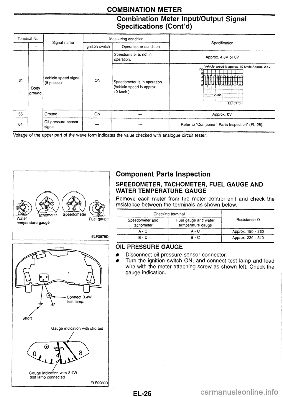
Component Parts inspection
SPEEDOMETER, TACHOMETER, FUEL GAUGE AND
WATER TEMPERATURE
GAUGE
Remove each meter from the meter control unit and check the
resistance between the terminals as shown below.
Checkina terminal I
Speedometer and I Fuel gauge and water I Resistance R
B-D I B-C I Approx. 230 - 310
tachometer
A-C
OIL PRESSURE GAUGE
Disconnect oil pressure sensor connector.
Turn the ignition switch ON, and connect test lamp and lead
wire with the meter attaching screw as shown left. Check the
gauge indication.
temperature gauge
A-C
ADD~OX.
190 - 260
Page 195 of 230

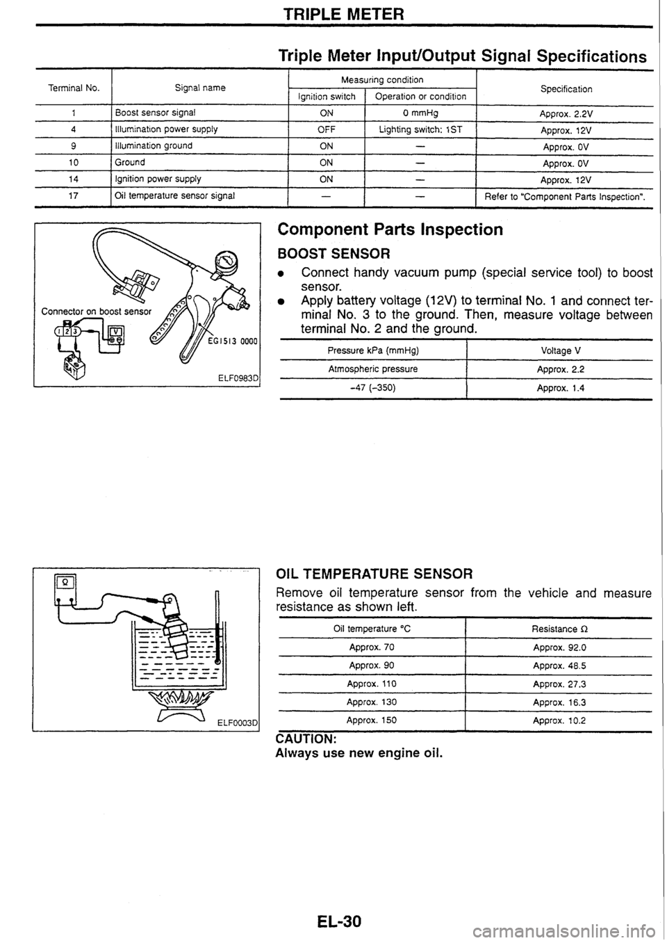
TRIPLE METER
Triple Meter InputlOutput Signal Specifications
Component
Parts Inspection
Terminal No.
1
4
9
10
14
17
BOOST SENSOR
Connect handy vacuum pump (special service tool) to boost
sensor.
Apply battery voltage (12V) to terminal No. 1 and connect ter-
minal No.
3 to the ground. Then, measure voltage between
terminal No.
2 and the ground.
I I - I Refer to "Component Parts Inspectionn.
Signal
name
Boost sensor signal
Illumination
power
supply
illumination ground
Ground ignition power supply
Oil temperature sensor signal
Pressure
kPa (mmHg) I Voltage V
I
- pp Atmospheric pressure Approx. 2.2
-47 (-350) 1 Approx. 1.4
-
Specification
Approx. 2.2V
Approx. 12V
Approx. OV
Approx.
OV
Approx. 12V
Measuring condition
OIL TEMPERATURE SENSOR
lgnition
switch
ON
OFF
ON
ON
ON
Remove oil temperature sensor from the vehicle and measure
resistance as shown
left.
Operation or condition
0 mmHg
Lighting switch: 1
ST
-
-
-
Oil temperature "C
Approx. 70
-- - - --
Resistance R
Approx. 92.0
Approx. 90
Approx.
110
Approx. 130 - -- Appro~. 48.5
Approx. 27.3
Approx. 16.3
Approx. 150
Approx. 10.2
CAUTION:
Always use new engine
oil.