sensor NISSAN GT-R 1998 Service Manual
[x] Cancel search | Manufacturer: NISSAN, Model Year: 1998, Model line: GT-R, Model: NISSAN GT-R 1998Pages: 230, PDF Size: 12.66 MB
Page 163 of 230
FULLY AUTOMATIC AIR CONDITIONER
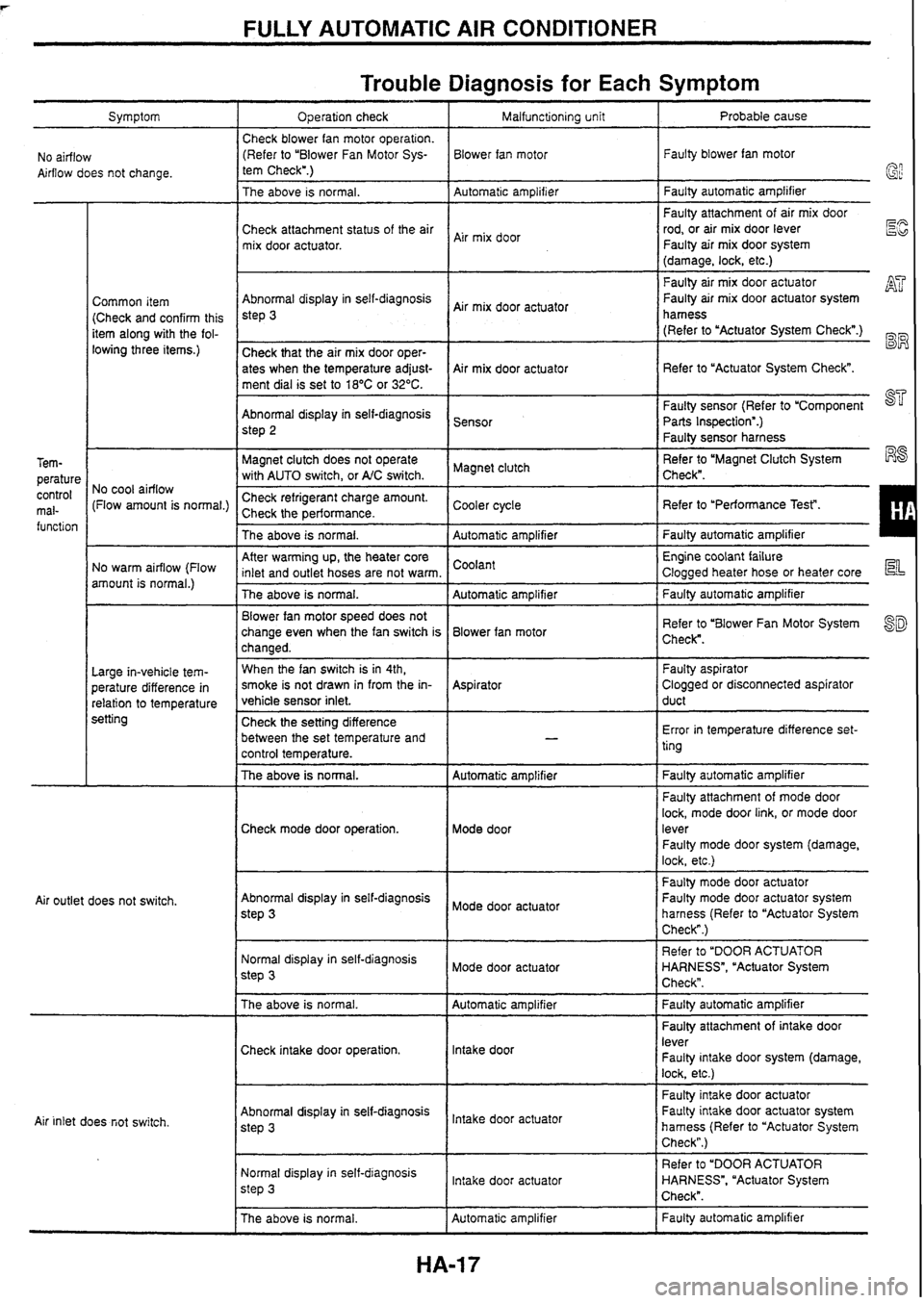
Symptom
Trouble Diagnosis for Each Symptom
No airflow
Airflow does not change. Operation check
Check blower fan motor operation. (Refer to "Blower Fan Motor Sys-
tem Check".)
The above is normal.
I Automatic amolifier 1 Faultv automatic amplifier
Faulty attachment of air mix door
rod, or air mix door lever
Faulty air mix door system
ElG
(damage, lock, etc.)
Malfunctioning unit
Blower fan motor Probable cause
Faulty blower fan motor
Check attachment status of the air
mix door actuator.
Common item (Check and confirm this
item along with the fol-
lowing three items.)
Air mix door
Abnormal display in self-diagnosis
step
3
Check that the air mix door oper-
ates when the temperature
adjust-
ment dial is set to
18OC or 32°C.
Faulty sensor (Refer to 'Component a
Parts Inspection".)
Faulty sensor harness
Air
mix door actuator
Air mix door actuator
Abnormal display in self-diagnosis
step 2
Magnet clutch does not operate
Magnet clutch Refer
to 'Magnet Clutch System R8
with AUTO switch, or A/C switch. Check".
I Faulty
air mix door actuator
Faulty air mix door actuator system AT
hamess
(Refer to "Actuator System Check".)
BW
Refer to "Actuator System Check".
@'i?
Sensor
Tem- perature
control mal-
function No
cool airflow
(Flow amount is normal.)
ngeranr
cnarge
amounr.
( Cooler cycle 2 ~erformance. I Refer to 'Performance Test". I
The above is normal. I Automatic amolifier 1 Faulty automatic amplifier I
After warming up, the heater core
inlet and outlet hoses are not warm. 1 Coolant I
Engine coolant failure
Clogged heater hose or heater core
No warm airflow
(Flow
amount is normal.)
The above is normal. Automatic amplifier
1 Faulty automatic amplifier
Blower fan motor speed does not
change even when the fan switch is Blower fan motor
changed. Refer
to "Blower Fan Motor System
Check".
I
When the fan switch is in 4th, Faulty aspirator
smoke is not drawn in from the
in-
Aspirator Clogged
or disconnected aspirator
vehicle sensor inlet. duct
Large
in-vehicle tem-
perature difference in
relation to temperature
setting Check the setting difference
between the set temperature and
control temperature. Error
in temperature difference set-
ting
- The above isnormal.- Automatic amplifier Faulty automatic amplifier
Faulty attachment of mode door
lock, mode door link, or mode door
Check mode door operation. Mode door lever
Faulty mode door system (damage,
lock, etc.)
Faulty mode door actuator
Abnormal display in self-diagnosis Faulty mode door actuator system
step
3 Mode door actuator
harness (Refer to "Actuator System
Check".)
Air
outlet does not switch.
Normal display in self-diagnosis
Mode door actuator
step
3
Refer to "DOOR ACTUATOR
HARNESS", "Actuator System
Check".
The above is normal.
I Automatic amplifier I Faulty automatic amplifier - - I I Faulty attachment of intake door
Check intake door operation. lntake
door lever
Faulty intake door system (damage,
lock, etc.)
~aulG intake door actuator
Faulty intake door actuator system
hamess (Refer to "Actuator System
Check".)
Abnormal
display in self-diagnosis
door step 3 Air inlet does fiot switch.
Normal display in self-diagnosis
lntake door actuator
step
3
Refer to "DOOR ACTUATOR
HARNESS", "Actuator System
Check".
I I The above is normal. I Automatic amplifier I Faulty automatic amplifier
Page 164 of 230
FULLY AUTOMATIC AIR CONDITIONER
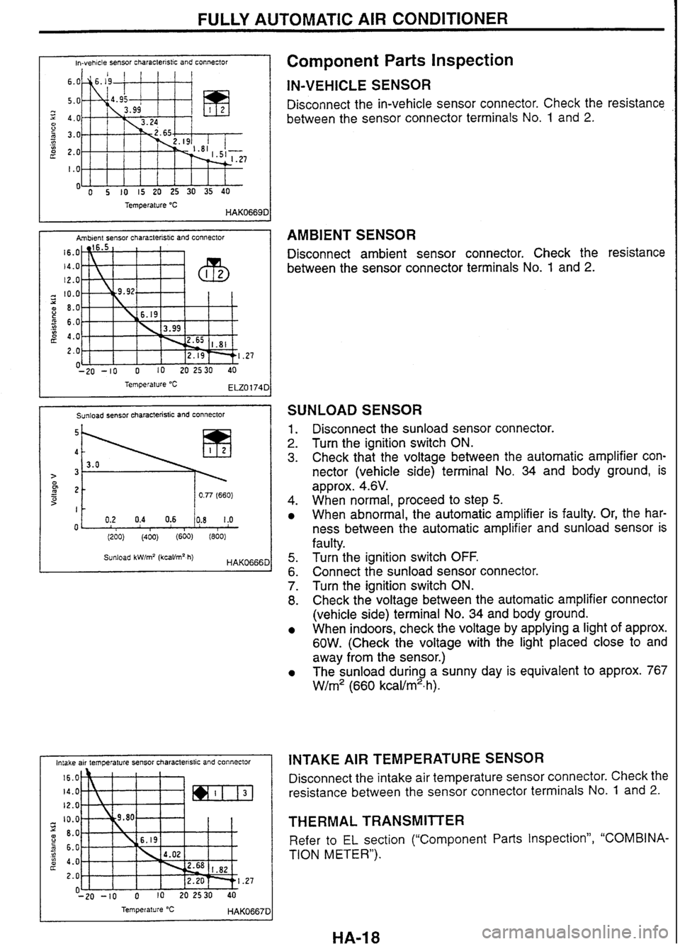
ln-vehcle sensor characterlstlc and connector I
Temperature "C HAK0669D
Ambient sensor characteristic and connector
Temperature
"C ELZ0174C
I Sunload sensor characteristic and connector
I Sunload kW/m2 (kcaVm2 h) HAK0666C
cake alr temperature sensor characlerlstrc and connector
Temperature
'C ~~~0667~1
Component Parts Inspection
IN-VEHICLE SENSOR
Disconnect the in-vehicle sensor connector. Check the resistance
between the sensor connector terminals No.
1 and 2.
AMBIENT SENSOR
Disconnect ambient sensor connector. Check the resistance
between the sensor connector terminals No.
1 and 2.
SUNLOAD SENSOR
Disconnect the sunload sensor connector.
Turn the ignition switch
ON.
Check that the voltage between the automatic amplifier con-
nector (vehicle side) terminal No.
34 and body ground, is
approx.
4.6V.
When normal, proceed to step
5.
When abnormal, the automatic amplifier is faulty. Or, the har-
ness between the automatic amplifier and
sunload sensor is
faulty. Turn the ignition switch
OFF.
Connect the sunload sensor connector.
Turn the ignition switch
ON.
Check the voltage between the automatic amplifier connector
(vehicle side) terminal
No. 34 and body ground.
When indoors, check the voltage by applying a light of approx.
60W. (Check the voltage with the light placed close to and
away from the sensor.)
The
sunload during a sunny day is equivalent to approx.
767
W/m2 (660 kcal/m2- h).
INTAKE AIR TEMPERATURE SENSOR
Disconnect the intake air temperature sensor connector. Check the
resistance between the sensor connector terminals No.
1 and 2.
THERMAL TRANSMITER
Refer to EL section ("Component Parts Inspection", "COMBINA-
TION
METER").
HA-I 8
Page 178 of 230
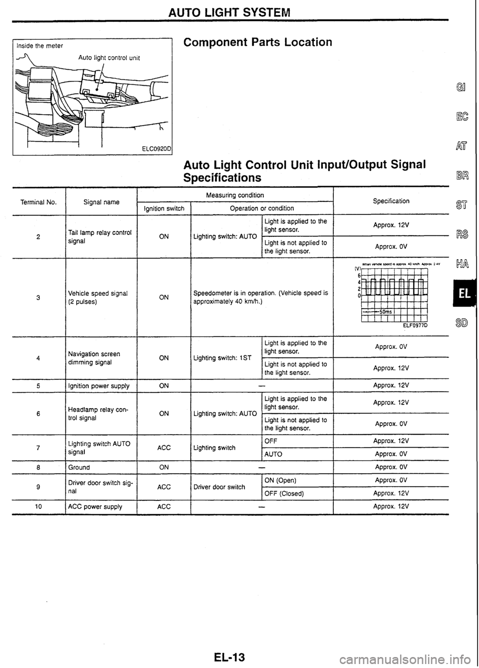
AUTO LIGHT SYSTEM
Component
Parts Location Inside the meter
-4 Auto light control unit
Auto Light Control Unit InputlOutput Signal
Specifications
Terminal No. Measuring
condition
Operation or condition
I
Signal name Specification
Ignition switch
I Light is applied to the I Approx. 12V
liaht sensor.
Tail lamp relay control
signal
Speedometer is in operation. (Vehicle speed is
approximately 40
kmlh.)
Lighting switch: AUTO
Vehicle speed signal (2 pulses)
Light is applied to the
liaht
sensor.
I
4
Light is not applied to
the light sensor.
Approx. OV
Approx.
OV
Navigation screen
dimming signal Liahtina
switch: 1 ST
- I I
I
Light is not applied to
the light sensor.
ignition power supply Approx. 12V
I - I
I Light
is applied to the I Approx. 12V
liaht sensor. Approx. 12V
Headlamp
relay con-
trol signal Lighting
switch: AUTO
Lighting switch AUTO
signal Lighting switch
ACC -
Light is not applied to
the light sensor.
Ground Approx.
OV
OFF
AUTO Approx. 12V
Approx. OV
Driver door switch sig-
n
al
ACC Approx.
OV
Approx.
OV
Approx. 12V
-
ACC power supply Driver
door switch
ACC ON
(Open)
OFF (Closed)
- I Approx. 12V
Page 188 of 230
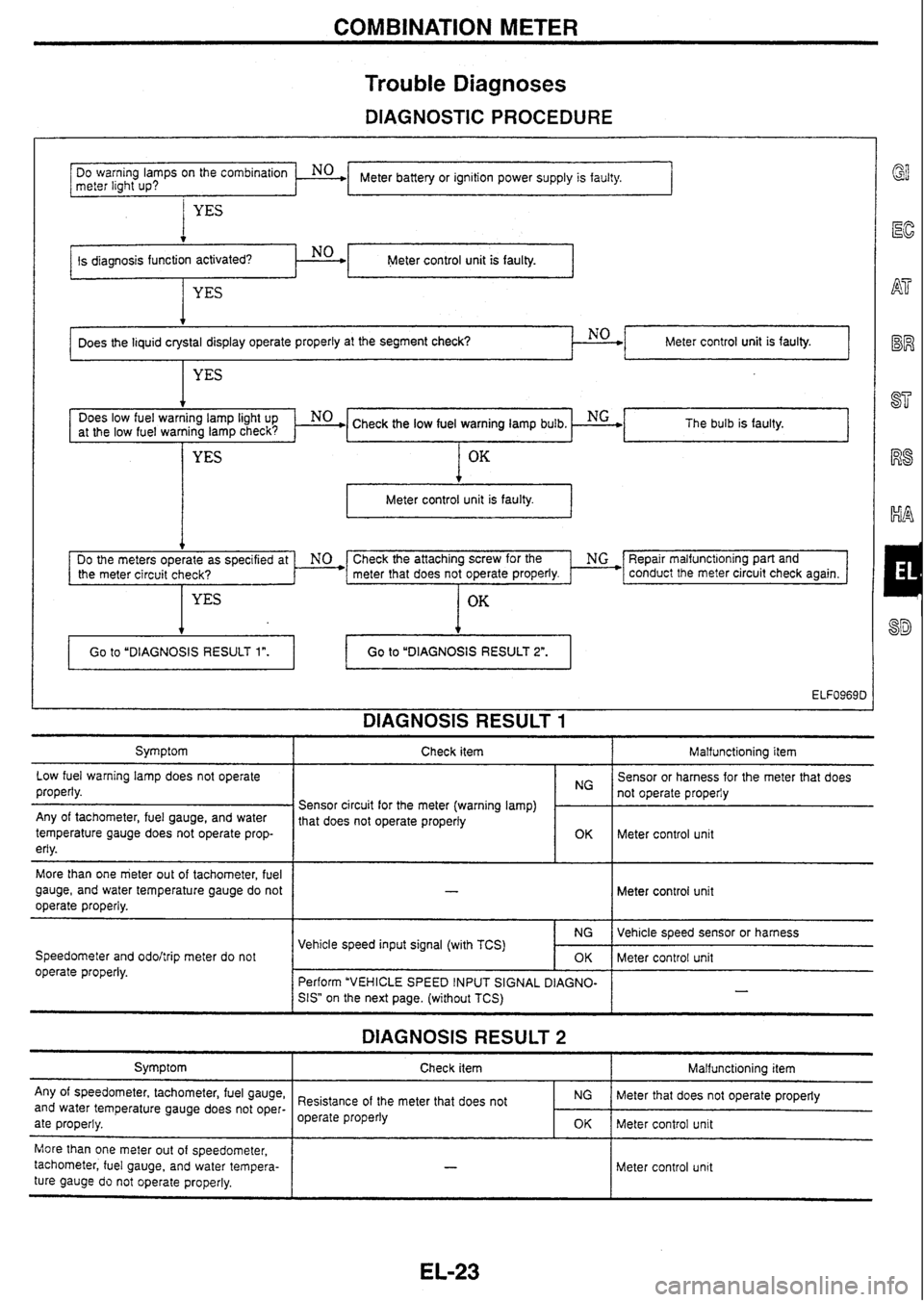
COMBINATION METER
Trouble
Diagnoses
DIAGNOSTIC PROCEDURE
I YES
Meter control unit is faulty.
Meter battery or ignition power supply is faulty.
DO
warning
lamps
on
the
meter light
up?
. No .
at the low fuel warning lamp check? The bulb
is faulty.
t
Meter control unit is faulty. I
Does the liquid crystal display operate properly at the segment check? NO
Check the attaching screw for the ' NG *F3epair malfunct~oning part and
the meter circuit check? meter that
does not operate properly. * conduct the meter circuit check again.
OK
Meter control unit is faulty.
YES
DIAGNOSIS RESULT 1
4
Symptom I Check item I Malfunctioning item
Go
to "DIAGNOSIS RESULT
1".
Low fuel warning lamp does not operate
properly. Go to
"DIAGNOSIS RESULT
2".
Any of tachometer, fuel gauge, and water
temperature gauge does not operate prop-
erly.
More than one meter out of tachometer, fuel
gauge, and water temperature gauge do not
operate properly.
Speedometer and
odohrip meter do not
operate properly. Sensor
or harness for the meter that does
Sensor circuit for the meter (warning lamp)
1 1: 1 not operate properiy
1 that does not operate properly
~ Meter control unit
Meter control unit
DIAGNOSIS RESULT 2
Symptom
Any of speedometer, tachometer, fuel gauge,
and water temperature gauge does not oper-
ate properly. Vehicle
speed sensor or harness
Meter control unit
-
Vehicle speed input signal (with TCS)
Check item
I Malfunctioning item
NG
OK
Perform "VEHICLE SPEED INPUT SIGNAL
DIAGNO-
SIS"
on the next page. (without TCS)
More than one meter out of speedometer,
tachometer, fuel gauge, and water tempera-
ture gauge
do not operate properly. Resistance
of the meter that does not
operate properly
Meter control unit
NG
OK
- -
Meter that does not operate properly
Meter control unit
Page 191 of 230
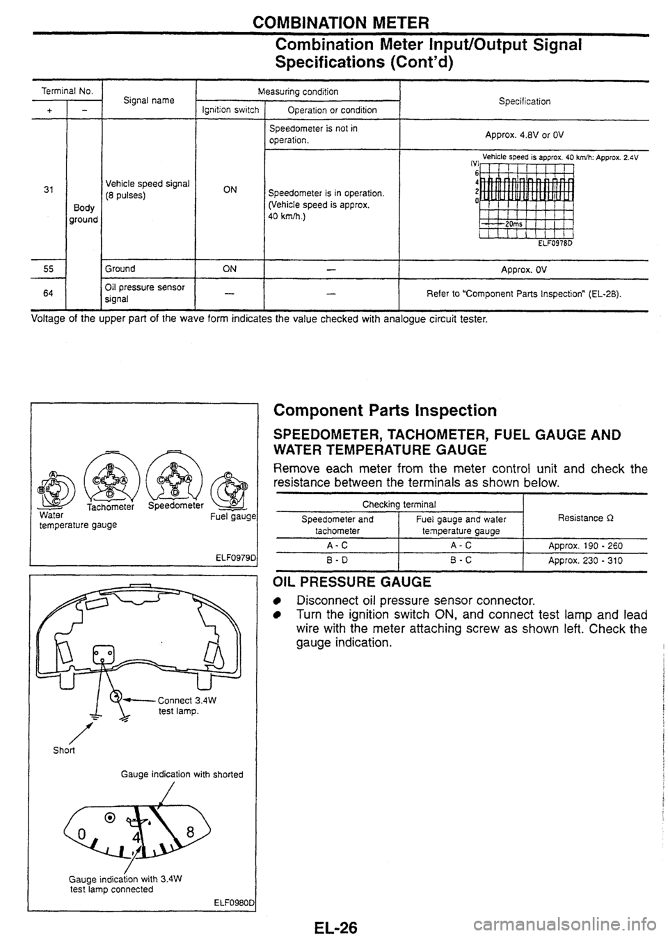
COMBINATION METER
Combination Meter Input/Output Signal -
Specifications (~ont'd)
Signal name
Vehicle speed signal
(8 pulses)
Body
ground
Ground
I--
Oil pressure sensor
signal Measuring
condi!ion
operation.
Speedometer is in operation.
(Vehicle speed is approx.
40 km~h.)
Specification
Approx.
4.8V or OV
Vehicle speed is approx. 40
ELF0978D
-- - Approx. 2.4V
ON - Approx. OV
- I - I Refer to 'Component Parts Inspection" (EL-28).
J I I Voltage of the upper part of the wave form indicates the value checked with analogue circuit tester.
- Water Fuel gaugc
temperature gauge
1 Gauge indication with shorted
Gauge
indicaion with
3.4W test lamp connected
ELF0980D
Component Parts inspection
SPEEDOMETER, TACHOMETER, FUEL GAUGE AND
WATER TEMPERATURE
GAUGE
Remove each meter from the meter control unit and check the
resistance between the terminals as shown below.
Checkina terminal I
Speedometer and I Fuel gauge and water I Resistance R
B-D I B-C I Approx. 230 - 310
tachometer
A-C
OIL PRESSURE GAUGE
Disconnect oil pressure sensor connector.
Turn the ignition switch ON, and connect test lamp and lead
wire with the meter attaching screw as shown left. Check the
gauge indication.
temperature gauge
A-C
ADD~OX.
190 - 260
Page 193 of 230
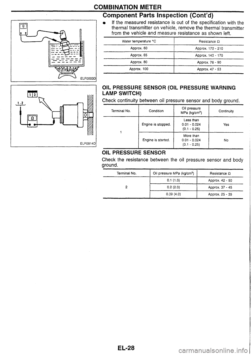
COMBINATION METER
Component Parts Inspection (Cont'd)
If the measured resistance is out of the specification with the
thermal transmitter on vehicle, remove the thermal transmitter
from the vehicle and measure resistance as
shown left.
Water temperature "C 1 Resistance R
Approx. 60 I Approx. i70 - 21 0
Approx. 65 I Approx. 140 - 170
Approx. 80 I Approx. 76 - 90
I
- - -- Appro~. 100 Approx. 47 - 53
OIL PRESSURE SENSOR (OIL PRESSURE WARNING
LAMP SWITCH)
Check continuity between oil pressure sensor and body ground.
Terminal No.
OIL PRESSURE SENSOR
Engine is stopped.
Engine is started.
Check the resistance between the oil pressure sensor and body
ground.
Condition
Terminal No.
I Oil pressure MPa (kgkmq-1 Resistance R
Oil pressure
MPa (kg/cm2) 1 Continuity
Less than
0.01 - 0.024
(0.1 - 0.25)
More than 0.01 - 0.024
(0.1 - 0.25)
0.2 (2.0) Approx. 37 - 45
Yes
No
Page 194 of 230
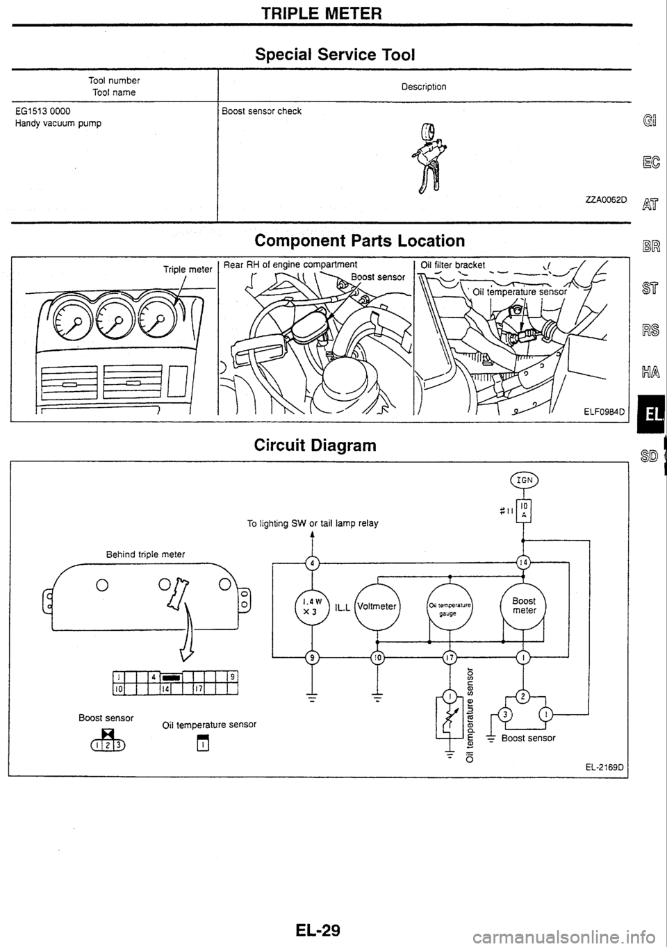
TRIPLE METER
Special Service Tool
Tool number
Tool name Description
i
€GI 51 3 0000 Boost sensor
check
Handy vacuum pump
Component Parts Location
Triple meter
I
Circuit Diagram
Behind triple meter
h
To lighting SW or tail lamp relay
Boost sensor
Oil temperature sensor
* BOOS^ sensor
Page 195 of 230
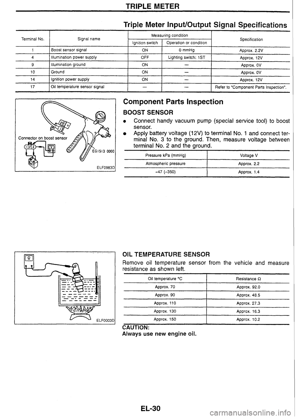
TRIPLE METER
Triple Meter InputlOutput Signal Specifications
Component
Parts Inspection
Terminal No.
1
4
9
10
14
17
BOOST SENSOR
Connect handy vacuum pump (special service tool) to boost
sensor.
Apply battery voltage (12V) to terminal No. 1 and connect ter-
minal No.
3 to the ground. Then, measure voltage between
terminal No.
2 and the ground.
I I - I Refer to "Component Parts Inspectionn.
Signal
name
Boost sensor signal
Illumination
power
supply
illumination ground
Ground ignition power supply
Oil temperature sensor signal
Pressure
kPa (mmHg) I Voltage V
I
- pp Atmospheric pressure Approx. 2.2
-47 (-350) 1 Approx. 1.4
-
Specification
Approx. 2.2V
Approx. 12V
Approx. OV
Approx.
OV
Approx. 12V
Measuring condition
OIL TEMPERATURE SENSOR
lgnition
switch
ON
OFF
ON
ON
ON
Remove oil temperature sensor from the vehicle and measure
resistance as shown
left.
Operation or condition
0 mmHg
Lighting switch: 1
ST
-
-
-
Oil temperature "C
Approx. 70
-- - - --
Resistance R
Approx. 92.0
Approx. 90
Approx.
110
Approx. 130 - -- Appro~. 48.5
Approx. 27.3
Approx. 16.3
Approx. 150
Approx. 10.2
CAUTION:
Always use new engine
oil.
Page 203 of 230
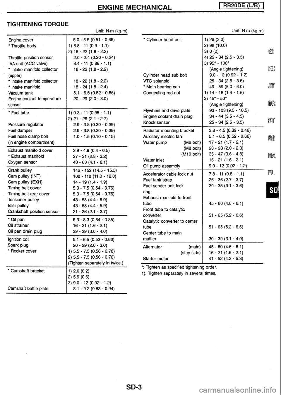
ENGINE MECHANICAL [ RB20DE (UB) 1
TIGHTENING TORQUE
Unit: N.m (kg-m)
Engine cover
Throttle body
Throttle position sensor
IAA unit (ACC valve)
lntake manifold collector
(upper)
Intake manifold collector
Intake manifold
Vacuum tank
Engine coolant temperature
sensor
- --
' Fuel tube
Pressure regulator
Fuel damper
Fuel hose clamp bolt
(in engine compartment)
Exhaust manifold cover
' Exhaust manifold
Oxygen sensor
Crank pulley
Cam pulley (INT)
Cam pulley
(EXH)
Timing belt cover
Timing belt rear cover
Tensioner pulley
Idler pulley
Crankshaft position sensor
' Oil pan
Oil strainer
Oil pan drain plug
ignition coil
Spark plug
* Rocker cover
Camshaft bracket
Camshaft baffle plate 5.1
- 6.5 (0.52 - 0.66)
20
- 29 (2.0 - 3.0)
1) 5.5 - 7.5 (0.56 - 0.76)
?) 5.5 - 7.5 (0.56 - 0.76)
:Tighten separately in twice.)
Cylinder head bolt
Cylinder head sub bolt
VTC solenoid
' Main bearing cap
Connecting rod nut
Flywheel and drive plate
Engine coolant drain plug
Knock sensor
Radiator mounting bracket
Auxiliary electric fan
Water pump (M6 bolt)
(M8 bolt)
(MI 0 bolt)
Water inlet
Oil pump assembly
Accelerator cable
lock nut
Fuel tank strap
Fuel sender unit lock
ring
Exhaust manifold to front
tube Front tube to catalytic
converter Catalytic converter to cent
tube Center tube to main
muffler
Alternator (main)
(stay side)
Starter motor Unit:
N-m (kg-m)
1)
29 (3.0)
2) 98 (10.0)
3)
0
(0)
4) 25
- 34 (2.5 - 3.5) GI
5) 95" - 100"
(Angle tightening)
Ec
9.0 - 12 (0.92 - 1.2)
25
- 34 (2.5 - 3.5)
49
- 59 (5.0 - 6.0) h$7'
1) 14 - 16 (1.4 - 1.6)
2) 45"
- 50"
(Angle tightening)
BW
93 - 103 (9.5 - 10.5)
34 - 44 (3.5 - 4.5)
25
- 34 (2.5 - 3.5) ST
': Tighten as specified tightening order.
1): Tighten separately in several times.
Page 205 of 230
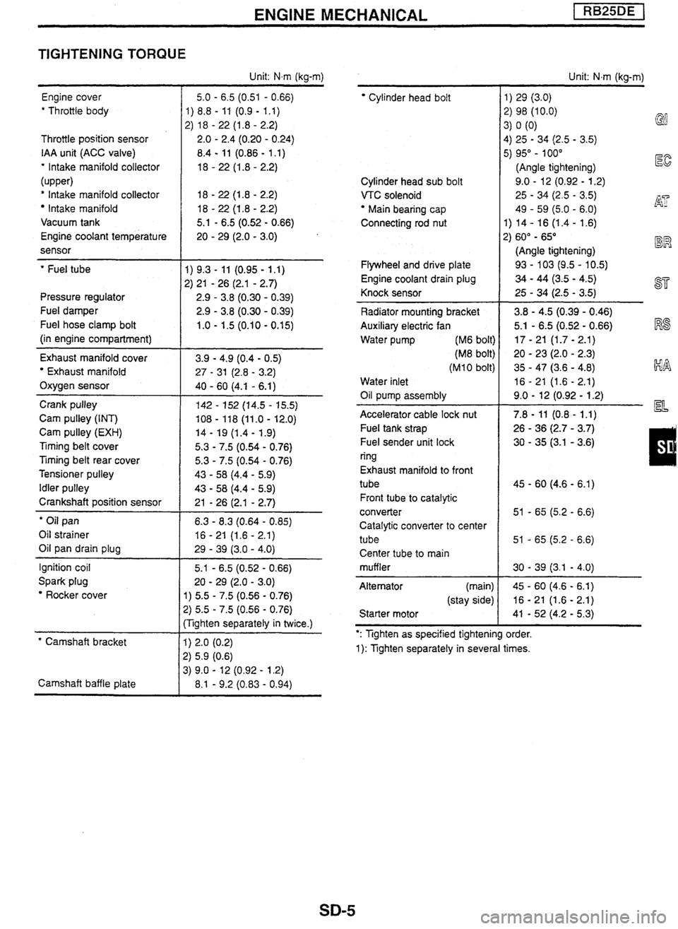
ENGINE MECHANICAL
TIGHTENING TORQUE
Engine cover
' Throttle body
Throttle position sensor
IAA unit (ACC valve)
' Intake manifold collector
(upper)
' Intake manifold collector
Intake manifold
Vacuum tank
Engine coolant temperature
sensor
' Fuel tube
Pressure regulator
Fuel damper
Fuel hose clamp bolt
(in engine compartment)
Exhaust manifold cover
Exhaust manifold
Oxygen sensor
Crank pulley
Cam pulley (INT)
Cam pulley
(EXH)
Timing belt cover
Ttming belt rear cover
Tensioner pulley
Idler pulley
Crankshaft position sensor
' Oil pan
Oil strainer
Oil pan drain plug
Ignition coil
Spark plug
Rocker cover
* Camshaft bracket
Camshaft baffle plate Unit:
Nm (kg-m)
5.0
- 6.5 (0.51 - 0.66)
1) 8.8
- 11 (0.9 - 1.1)
2) 18
- 22 (1.8 - 2.2)
2.0
- 2.4 (0.20 - 0.24)
8.4
- 11 (0.86 - 1 .I)
18
- 22 (1.8 - 2.2)
5.1
- 6.5 (0.52 - 0.66)
20
- 29 (2.0 - 3.0)
1) 5.5 - 7.5 (0.56 - 0.76)
2) 5.5 - 7.5 (0.56 - 0.76)
:Tighten separately in twice.)
Cylinder head bolt
Cylinder head sub bolt
VTC solenoid
Main bearing cap
Connecting rod nut
Flywheel and drive plate
Engine coolant drain plug
Knock sensor
Radiator mounting bracket
Auxiliary electric fan
Water pump
(M6 bolt)
(M8 bolt)
(M 1 0 bolt)
Water inlet
Oil pump assembly
-
Accelerator cable lock nut
Fuel tank strap
Fuel sender unit lock
ring
Exhaust manifold to front
tube
Front tube to catalytic
converter
Catalytic converter to center
tube Center tube to main
muffler
Alternator (main)
(stay side)
Starter motor Unit:
N.m (kg-m)
1) 29 (3.0)
2) 98 (10.0) 3) 0 (0)
@
4)
25 - 34 (2.5 - 3.5)
5) 95" - 100"
(Angle tightening)
E
9.0 - 12 (0.92 - 1.2)
25
- 34 (2.5 - 3.5) j$? 49 - 59 (5.0 - 6.0)
1) 14- 16
(1.4- 1.6)
2) 60"
- 65" BR
(Angle tightening)
93
- 103 (9.5 - 10.5)
34 - 44 (3.5 - 4.5)
25
- 34 (2.5 - 3.5) a=
': Tighten as specified tightening order.
1): Tighten separately in several times.