ECO mode NISSAN GT-R 1998 Service Manual
[x] Cancel search | Manufacturer: NISSAN, Model Year: 1998, Model line: GT-R, Model: NISSAN GT-R 1998Pages: 230, PDF Size: 12.66 MB
Page 2 of 230
NISSAN
MODEL R34 SERIES
FOREWORD
This Sewice Manual contains infor-
mation concerning necessary ser-
vice procedures and relevant data
for the model
R34 series.
All information, illustrations and
specifications contained in this Ser-
vice Manual are based on the latest
product information available at the
time of publication. If your NISSAN
model differs from the specifications
contained in this
Sewice Manual,
consult your NISSAN distributor for
information.
The right is resewed to make
changes in specifications and meth-
ods at any time without notice.
QUICK REFERENCE INDEX I
0 1998 KISSAN MOTOR CO., LTD. Printed in Japan
A11 rights reserved. No part of this Service Manual may be reproduced or stored in a retrieval system, or transmitted in any form, or by any means, electronic, mechanical, photocopying, recording or otherwise, without the prior written permission of Nissan Motor Company Ltd.. Tokyo, Japan.
Page 5 of 230
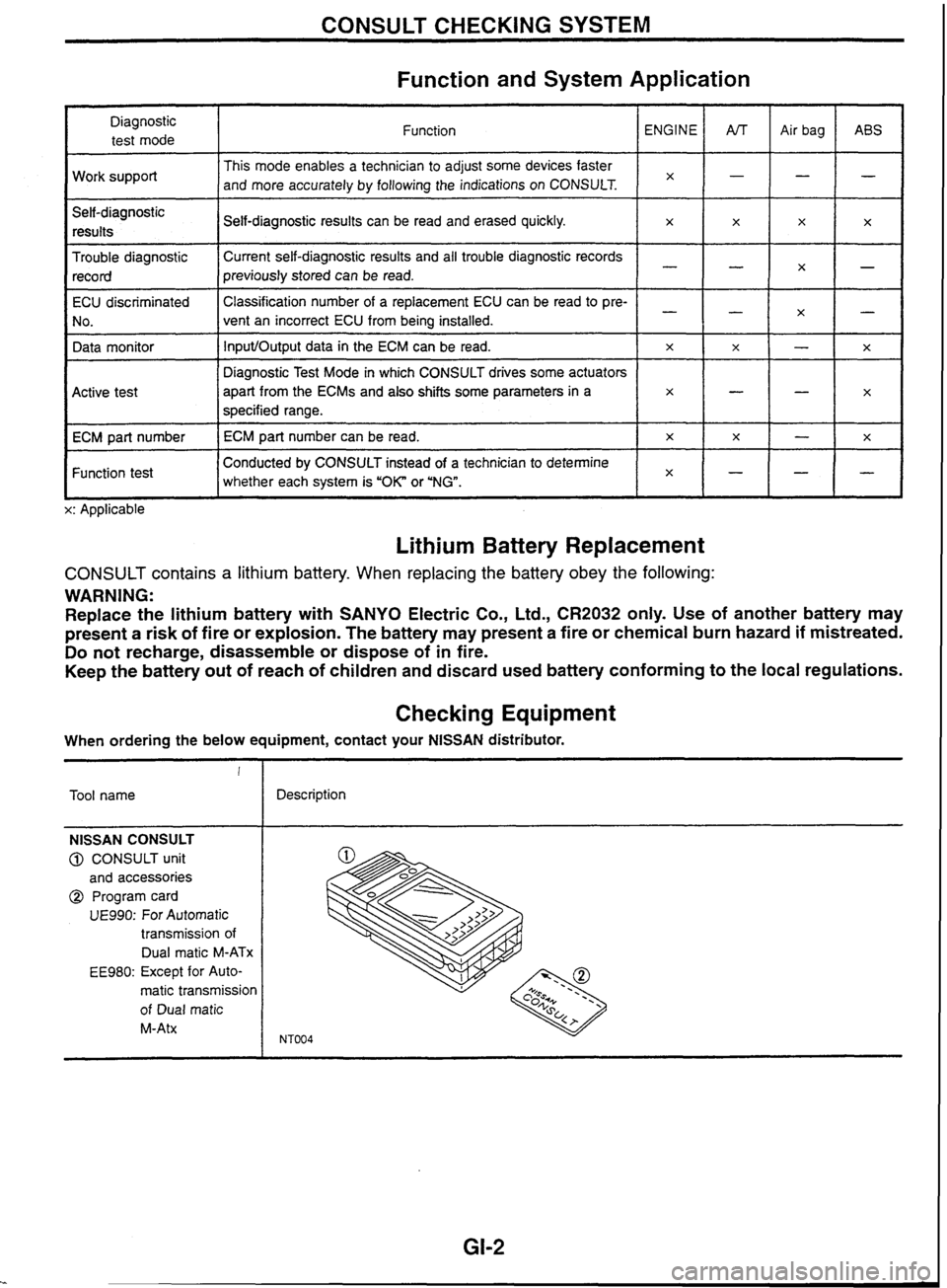
CONSULT CHECKING SYSTEM
Function and System Application
Diagnostic test mode
Work support
Self-diagnostic results
Trouble diagnostic record Function
This mode enables a technician to adjust some devices faster
and more accurately by following the indications on CONSULT.
ECU discriminated
No.
Data monitor
I I whether each system is "OK" or 'NG". lxH-1-
Conducted by CONSULT instead of a technician to determine
Function test Self-diagnostic
results can be read and erased quickly.
Current self-diagnostic results and all trouble diagnostic records
previously stored can be read.
Active test
ECM part number
L x: Applicable ENGINE
x
Classification
number of a replacement ECU can be read to pre-
vent an incorrect ECU from being installed.
InputIOutput data in the ECM can be read.
Lithium Battery Replacement
x
Diagnostic Test Mode in which CONSULT drives some actuators
apart from the
ECMs and also shifts some parameters
in a
specified range.
ECM part number can be read.
CONSULT contains a lithium battery. When replacing the battery obey the following:
WARNING:
Replace the lithium battery with SANYO Electric Co., Ltd.,
CR2032 only. Use of another battery may
present
a risk of fire or explosion. The battery may present a fire or chemical burn hazard if mistreated.
Do not recharge, disassemble or dispose of in fire.
Keep the battery out of reach of children and discard used battery conforming to the local regulations.
AfT
-
-
x
Checking Equipment
x
-
x
x
When ordering the below equipment, contact your NlSSAN distributor. Air
bag
-
-
-
x
!
Tool name ABS
-
x
X
-
x
NISSAN CONSULT
@ CONSULT unit
and accessories
@ Program card
UE990: For Automatic
transmission of
Dual
rnatic M-ATx
EE980: Except for Auto-
matic transmission
of Dual
matic
M-Atx
x
-
--
X
-
Description
-
x
-
-
x
x
Page 23 of 230
Self-diagnosis
DESCRIPTION
In self-diagnosis, when any of the critical sensors in the engine control system fails and the self-diagnos-
tic malfunction detection conditions are satisfied, the malfunctioning system is stored in the control unit for
easier trouble diagnosis.
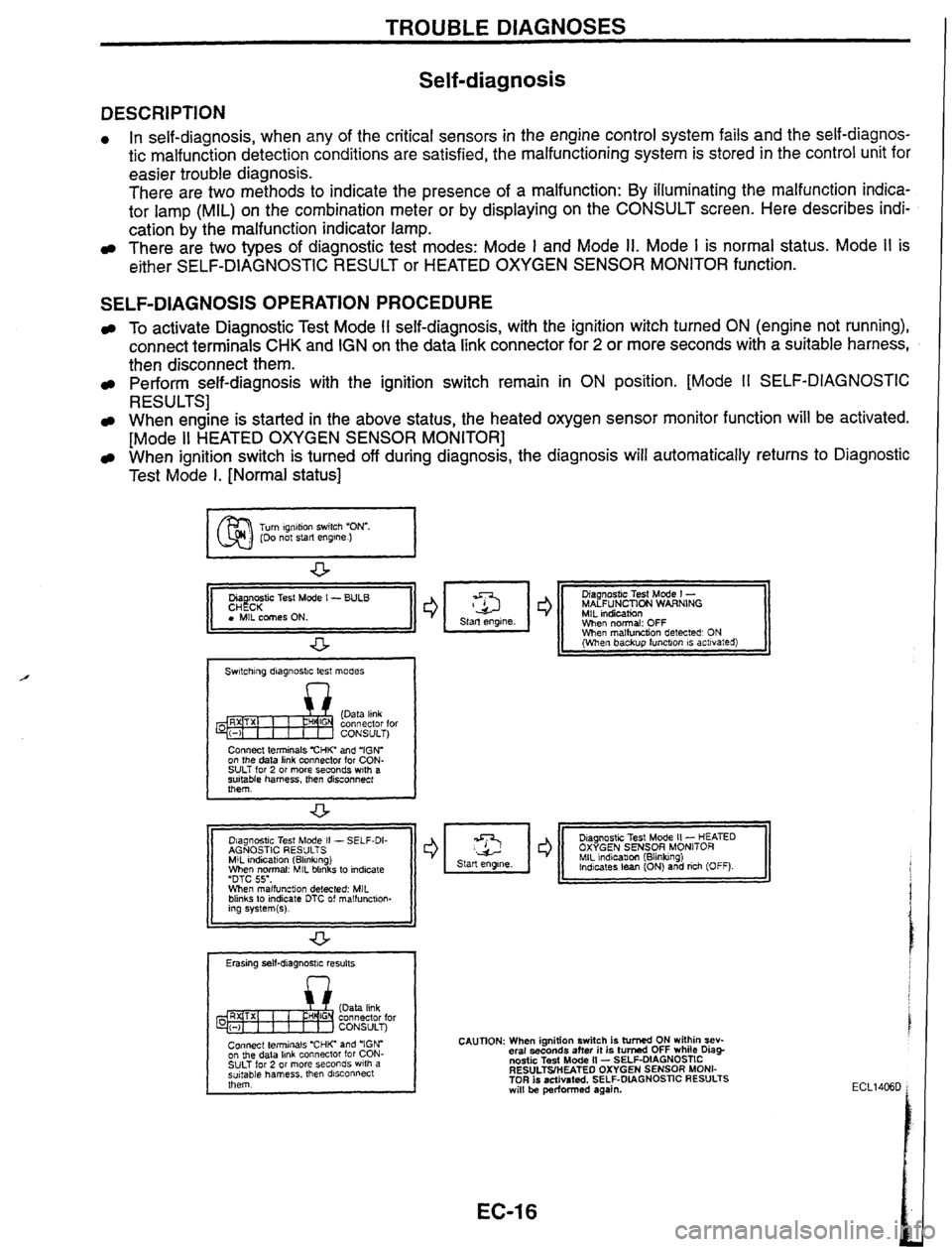
There are two methods to indicate the presence of a malfunction: By illuminating the malfunction indica-
tor lamp (MIL) on the combination meter or by displaying on the CONSULT screen. Here describes indi-
cation by the malfunction indicator lamp.
There are two types of diagnostic test modes: Mode I and Mode 11. Mode I is normal status. Mode I1 is
either SELF-DIAGNOSTIC RESULT or
HEATED OXYGEN SENSOR MONITOR function.
SELF-DIAGNOSIS OPERATION PROCEDURE
To activate Diagnostic Test Mode I1 self-diagnosis, with the ignition witch turned ON (engine not running),
connect terminals CHK and IGN on the data link connector for
2 or more seconds with a suitable harness,
then disconnect them.
Perform self-diagnosis with the ignition switch remain in ON position. [Mode I1 SELF-DIAGNOSTIC
RESULTS]
When engine is started in the above status, the heated oxygen sensor monitor function will be activated.
[Mode
II HEATED OXYGEN SENSOR MONITOR]
When ignition switch is turned off during diagnosis, the diagnosis will automatically returns to Diagnostic
Test Mode
I. [Normal status]
I 1 r I, rest Mode I - I I I r II MAL~UNLMNI WARNlNfi +
Switching diagnostic test modes
n
Connect terminals "CHIC and 'IGN'
on the data link connector for CON-
SULT for
2 or more seconds w~th a
suitable harness, then disconnect
them.
Diagnostic Test Mode
II
- SELF-DI- Diagnostic
Test Mode I1 - HEATED AGNOSTIC RESULTS OXYGEN SENSOR MONITOR
MIL indication (Blinkmg) MIL indicabon (Blinking)
When normal: MIL blinks to indicate Indicates
lean (ON) and rich
(OFF).
'DTC 55'. When malfunction detected: MIL
blinks to indicate DTC of
malfunction-
11 ing systern(s). I I
Erasing self-diagnostic results
Connect Leyinals
'CHIC and 'IGN"
on
the
data
hnk
connector for CON-
SULT for
2 or more seconds with a
suitable harness. then
dsconnect
them.
CAUTION: When ignition switch is turned ON within sev-
eral seconds after it is
turned OFF wh~le Diag-
nostic Test Mode II - SELF-DIAGNOSTIC
RESULTSIHEATEO
OXYGEN SENSOR MONI-
TOR
is activated, SELF-DIAGNOSTIC RESULTS will be performed again.
Page 24 of 230
TROUBLE DIAGNOSES
Self-diagnosis (Cont'd)
I Malfunction indicator lamp
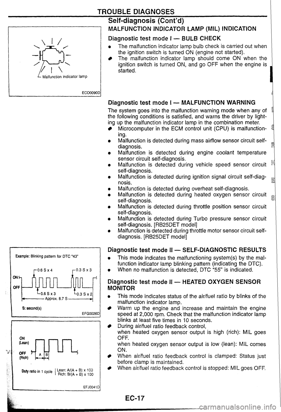
MALFUNCTiON INDICATOR LAMP (MIL) INDICATION
Diagnostic test mode I - BULB CHECK
0 The malfunction indicator lamp bulb check is carried out when
the ignition switch is turned
ON (engine not started).
The malfunction indicator lamp should come ON when the
ignition switch is turned
ON, and go OFF when the engine is
started.
Example: Blinking pattern for DTC "43"
ONh
OFF
Approx. 8.7 S
OFF (Rich)
Duty ratio in 1 cycle 1 Lean: Al(A + B) x 100 Rich: B/(A + B) x 100
EFJ0041 C
Diagnostic test mode I - MALFUNCTION WARNING
The system goes into the malfunction warning mode when any of
the following conditions is satisfied, and warns the driver by light-
ing up the malfunction indicator lamp in the combination meter.
Microcomputer in the ECM control unit (CPU) is malfunction-
1
ing.
Malfunction is detected during mass airflow sensor circuit self-
diagnosis.
Malfunction is detected during engine coolant temperature
sensor circuit self-diagnosis.
Malfunction is detected during vehicle speed sensor circuit
self-diagnosis.
Malfunction is detected during ignition signal circuit
self-diag-
nosis.
Malfunction is detected during overheat self-diagnosis.
Malfunction is detected during heated oxygen sensor circuit
self-diagnosis.
~alfunsion is detected during throttle position sensor circuit
self-diagnosis.
Malfunction is detected during Turbo pressure sensor circuit
self-diagnosis.
[RB25DET model]
Malfunction is detected during throttle motor sensor circuit self-
diagnosis.
[RB25DET model]
Diagnostic test mode I1 - SELF-DIAGNOSTIC RESULTS
0 This mode indicates the malfunctioning system(s) by the mal-
function indicator lamp blinking pattern (indicating the DTC).
0 When no malfunction is detected, DTC "55" is indicated.
Diagnostic test mode II - HEATED OXYGEN SENSOR
MONITOR
0 This mode indicates status of the aidfuel ratio by blinks of the
malfunction indicator lamp.
Warm up the engine and increase and maintain the engine
speed at 2,000 rpm. Check that the malfunction indicator lamp
blinks at least five times in
10 seconds.
During airlfuel ratio feedback control,
when heated oxygen sensor output is high (rich): MIL goes
OFF.
when heated oxygen sensor output is low (lean):
MIL comes
ON.
When aidfuel ratio feedback control is clamped: Status just
before clamp
is maintained.
When airifuel ratio feedback control is stopped: MIL goes OFF.
Page 25 of 230
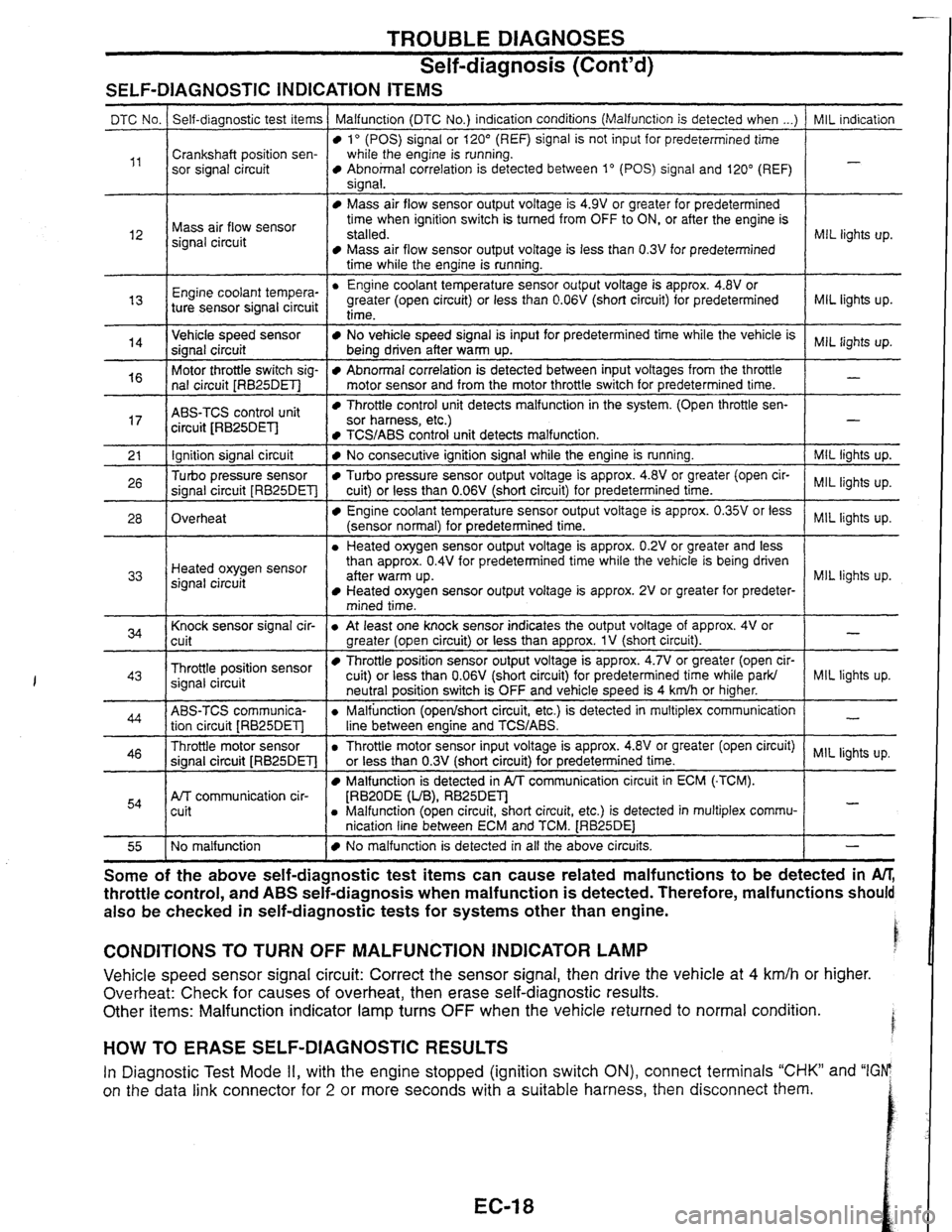
TROUBLE DIAGNOSES
Self-diagnosis
(Cont'd)
SELF-DIAGNOSTIC INDICATION ITEMS
I time while the engine is running. I
MIL indication
-
DTC No.
,,
MIL lights up. l2
Self-diagnostic test items
Crankshaft position sen-
sor signal circuit Malfunction (DTC No.)
indication conditions (Malfunction is detected when ...)
lo (POS) signal or 120" (REF) signal is not input for predetermined time
while the engine is running.
Abnohal correlation is detected between 1" (POS) signal and 120" (REF)
sianal.
Mass air flow sensor
signal circuit
MIL lights up.
Engine coo'ant tempera-
"
Mass air flow sensor output voltage is 4.9V or greater for predetermined
time when ignition switch is turned from OFF to ON, or after the engine is
stalled.
Mass air flow sensor output voltage is less than 0.3V for predetermined
Engine coolant temperature sensor output voltage is approx.
4.8V or
greater (open circuit) or less than
0.06V (short circuit) for predetermined
MIL lights up.
-
14
ABS-TCS control unit
circuit JRB25DEl-l
ture sensor signal circuit Throttle control unit detects malfunction
in the system. (Open throttle sen- sor harness, etc.)
Ignition signal circuit
Turbo pressure sensor
signal circuit
[RB25DET]
Overheat
I 1 mined time. I
time-
Vehicle speed sensor
signal circuit
Motor throttle switch sig-
nal circuit
[RB25DET]
TCS/ABS control unit detects malfunction. 1 -
I Knock sensor signal cir-
cuit
- --
No vehicle speed signal is input for predetermined time while the vehicle is
being driven after warm up.
Abnormal correlation is detected between input voltages from the throttle
motor sensor and from the motor throttle switch for predetermined time.
I
MIL lights up. Heated oxygen sensor
signal circuit
Throttle position sensor
signal circuit
No consecutive ignition signal while the engine is running.
Turbo pressure sensor output voltage is approx. 4.8V or greater (open cir-
cuit) or less than
0.06V (short circuit) for predetermined time.
Engine coolant temperature sensor output voltage is approx. 0.35V or less
(sensor normal) for predetermined time.
a Heated oxygen sensor output voltage is approx. 0.2V or greater and less
than approx.
0.4V for predetermined time while the vehicle is being driven
aner warm up. Heated oxygen sensor output voltage is approx. 2V or greater for predeter-
ABS-TCS communica- tion circuit
[RB25DET]
Throttle motor sensor
signal circuit
[RB25DET]
Afr communication cir-
cuit
MIL lights up.
lights
up.
MIL lights up.
NQ malfunction
I a At least one knock sensor indicates the output voltage of approx. 4V or
greater (open circuit) or less than approx.
1V (short circuit).
Throttle position sensor output voltage is approx. 4.7V or greater (open cir-
cuit) or less than
0.06V
(short circuit) for predetermined time while ark/
a Throttle motor sensor input voltage is approx. 418~or greater (open circuit) MIL lights up.
or less than
0.3V
(short circuit) for predetermined time. I
-
MIL liqhts up. neutral position switch is OFF and vehicle speed is 4 kdh or higher.
a Malfunction (openlshort circuit, etc.) is detected in multiplex communication
line between enaine and
TCWABS.
Malfunction is detected in PA communication circuit in ECM (-TCM).
[RBZODE (UB), RB25Dm a Malfunction (open circuit, short circuit, etc.) is detected in multiplex commu-
nication line between ECM and TCM.
[RB25DE1
-
-
No malfunction is detected in all the above circuits. I - - --
Some of the above ~elfaia~nostic test items can cause related malfunctions to be detected in M,
throttle control, and ABS seif-diagnosis when malfunction is detected. Therefore, malfunctions should
also be checked in self-diagnostic tests for systems other than engine.
CONDITIONS TO TURN OFF MALFUNCTION INDICATOR LAMP
Vehicle speed sensor signal circuit: Correct the sensor signal, then drive the vehicle at 4 km/h or higher.
Overheat: Check
for causes of overheat, then erase self-diagnostic results.
Other items: Malfunction indicator lamp turns
OFF when the vehicle returned to normal condition.
HOW TO ERASE SELF-DIAGNOSTIC RESULTS
In Diagnostic Test Mode II, with the engine stopped (ignition switch ON), connect terminals "CHK" and "IGFP
on the data link connector for
2 or more seconds with a suitable harness, then disconnect them.
Page 32 of 230

TROUBLE DIAGNOSES
CONSULT (Cont'd)
REAL TlME DIAGNOSIS IN DATA MONITOR MODE
CONSULT has two kinds of triggers and they can be selected by touching "SETTINGJy in "DATA MONITOR"
mode.
1. "AUTO TRIG" (Automatic trigger):
The malfunction will be identified on the CONSULT screen in real time.
In other words, malfunction item will be displayed at the moment the malfunction is detected by ECM. GI
DATA MONITOR can be performed continuously until a malfunction is detected. However, DATA MONI-
TOR cannot continue any longer after the malfunction detection.
2. "MANU TRIG" (Manual trigger):
Malfunction item will not be displayed automatically on CONSULT screen even though a malfunction
is detected by ECM.
DATA MONITOR can be performed continuously even though a malfunction is detected. I
AT
Use these triggers as follows: . 1. "AUTO TRIG"
While trying to detect the DTC by performing the "DTC CONFIRMATION PROCEDURE", be sure to BR
select to "DATA MONITOR (AUTO TRIG)" mode. You can confirm the malfunction at the moment it is
detected.
While narrowing down the possible causes, CONSULT should be set in "DATA MONITOR (AUTO ST
TRIG)" mode, especially in case the incident is intermittent.
When you are inspecting the circuit by gently shaking (or twisting) the suspicious connectors, compo-
Rs
nents and harness in the "DTC CONFIRMATION PROCEDURE, the moment a malfunction is found
the malfunction item will be displayed. (Refer to GI section,
"Incident
Simulation Tests" in
"HOW TO
PERFORM EFFICIENT DIAGNOSIS
FOR AN ELECTRICAL INCIDENT'.) HA
2. "MANU TRIG"
If the malfunction is displayed as soon as "DATA MONITOR" is selected, reset CONSULT to "MANU
TRIG".
By selecting "MANU TRIG" you can monitor and store the data. The data can be utilized for
further diagnosis, such as a comparison with the value for the normal operating condition.
I
I SELECT MONITOR ITEM 1
I MAIN SIGNALS
SELECTION FROM MENU
I I
-11 START I
I h SET RECORDING COND 1 1 k SET RECORDING CON0 1
I MANU TRIG I
I LONG TlME I
"AUTO TRIG"
A malfunction
can be
displayed on "DATA
MONITOR" screen
automatically
if detected. "MANU TRIG"
A
malfunction can not be
displayed
on "DATA
MONITOR" screen
automatically even
if
detected.
Page 33 of 230

TROUBLE DIAGNOSES t i
CONSULT (Cont'd) i
FUNCTION TEST MODE
CHECK ITEM (REMEDY)
FUNCTION
TEST
ITEM JUDGEMENT
CONDITION
lgnition switch: ON
(Engine stopped)
Displays the results of on board
diagnostic system.
SELF-DIAG
RESULTS Objective
system
--
ignition switch: ON
(Engine stopped)
Throttle position sensor circuit is
tested when throttle is opened and
closed fully. ("IDLE POSITION" is
the test item name for the vehicles
in which idle is selected by throttle
position sensor.) Harness and connector
Throttle position sensor (Closed
throttle position)
Throttle position sensor (Closed
throttle position) adjustment
Throttle linkage
Venfy operation in DATA
MONITOR mode.
Throttle
valve:
opened OFF
ON
CLOSED THROTTLE
POSl Throttle valve:
closed
lgnition switch: ON
(Engine stopped)
Throttle position sensor circuit is
tested when throttle is opened and
closed fully.
Harness and connector
Throttle position sensor
Throttle position sensor
adjustment
Throttle linkage
Verify operation in DATA
MONITOR mode.
Range
(Throttle
valve fully opened
- Throttle valve
fully closed) More
than 3.0V THROTTLE POSl
SEN CKT
lgnition switch: ON
(Engine stopped)
Neutral position switch circuit is
tested when shift lever is
manipulated.
lgnition switch: ON
(Engine stopped)
Fuel pump circuit is tested by
checking the pulsation in fuel
pressure when fuel tube is
pinched. Out of
N/P
positions OFF
Harness
and connector
Neutral position switch
Linkage adjustment
PARWNEUT POSl SW CKT
In
N/P positions
Harness and connector
Fuel pump
Fuel pump relay
Fuel filter clogging
Fuel level
There
is pressure pulsation on
the fuel feed hose.
FUEL PUMP
CIRCUIT
--
The valve timing control system is
diagnosed by checking for
operating sound of the solenoid
valve.
lgnition switch: ON
(Engine stopped)
Cooling fan circuit is tested when
cooling fan is rotated.
VALVE
TIMING
SN
CKT
Harness and connector
Cooling fan motor
Cooling fan relay
COOLING
FAN
CIRCUIT RB25DE, RB25DET
The cooling fan rotates and
stops every
3 seconds.
lgnition switch: ON -+ START
Start signal circuit is tested when
engine is started by operating the
starter. Battery voltage and water
temperature before cranking, and
average battery voltage, mass air
flow sensor output voltage and
cranking speed during cranking
are displayed.
Harness and connector
lgnition switch
START
SIGNAL
CIRCUIT Start
signal: OFF 3 ON
Page 37 of 230

TROUBLE DIAGNOSES
Symptom Matrix Chart (Cont'd)
Sensor-related problems I Symptom characteristics and ins~ection hints
Open Engine
will not start when either REF signal circuit or POS signal circuit is open.
Neither fuel system nor ignition system outputs control signals.
Crankshaft position sensor
(POS, REF) Instanta-
neous break Symptoms
vary with the break time and the vehicle's driving conditions. Light
shock or surging will occur while the vehicle is being driven, and the engine will
stall at idle speed.
Ring gear crankshaft position
sensor
[RB20DE
(UB)]
Signal
Mass air flow sensor Open
Open
High output
Low output I Aidfuel
ratio becomes lean. Dirty hot wire or air entering the system could be the
cause. No
airfluel ratio compensation
is carried out during lean bum status. Drivability
may be affected.
Enters fail-safe mode. Driving under
2,400 rpm is allowed.
Airlfuel
ratio becomes rich. Black smoke may be noted. Poor contact at the
ground could be the cause.
Engine coolant temperature sen-
sor Open
Open
Opedshort
High resis-
tance
Low resis-
tance
Opedshort
Heated oxygen sensor
I
Airlfuel ratio becomes over-rich.
Same symptom as when signal wire is open.
Enters fail-safe mode. Malfunction indicator lamp comes ON. Ordinary driving is
allowed. Problems tend to occur when engine is cold or engine coolant tempera-
ture
is high.
Detects low engine coolant temperature. Problems tend to occur after engine
warm-up.
Detects high engine coolant temperature. Problems tend to occur when engine is
cold.
Base
aidfuel ratio is used.
lgnition timing is retarded within the knock control range. Lack of power may be
OpedShort
I noted.
Knock sensor lgnition
timing is retarded within the knock control range. Lack of power may be
High
Output
(noted.
Low output
1 lgnition timing may not be retarded when knock is detected.
Vehicle speed sensor
Throttle position sensor
Opedshort
Opedshort
Unstable out-
put
Poor adjust-
ment
Open
Turbo pressure sensor
(TE) Fuel
cut time becomes-shorter, or no fuel cut is observed.
Base idle speed is used. Fuel injection is not increased during acceleration.
AIT shift point changes for AfF vehicles.
Unnecessary cut-in fuel injection could be the cause. Poor contact at the ground
or control unit could be the cause.
ldle judgment is "OFF while idling. Condition returns
normal by turning the igni-
tion switch ON and OFF repeatedly.
Turbo pressure is judged zero. No remarkable malfunction will be detected.
Refrigerant pressure is judged high. ldle speed remains high while the air condi-
tioner is ON.
Refrigerant pressure sensor
Short Refrigerant pressure
is judged low. ldle speed remains low while the air condi-
tioner is ON.
lgnition switch (IGN)
lgnition switch (START)
Air conditioner switch Open
Engine
will not start because neither fuel system nor ignition system outputs con-
trol signals.
Engine starts in normal condition. Engine may not start when temperature is
extremefy
low.
Air conditioner will not operate. No other malfunction will be noted.
Park/neutral
position switch is judged "OFF. Target engine speed for cold engine
in
N or P position is reduced.
ParWneutral position switch is judged
"0N"I Fast Jdle is effective when the engine
is cold and the gear is in other than N and P posrtlons. Vehrcle excessrvely
creeps.
Open
Open
Parklneutral
position
switch
Short
Power steering oil pressure
switch Open
Engine may
stall when the steering wheel is turned while the vehicle is standstill
and the accelerator pedal is lightly pressed, or when the steering wheel is turned
Electrical load switch Short
Open
Open/short
Multiplex communication line
- -- during deceleration. '
Power steering switch is judged 'ON." Value will be compensated constantly.
Idle speed drops so that the engine can stall when electrical load is applied.
Torque reduction control is not performed. Therefore,
shift shock becomes
greater.
- -- -- -- -- Engine will not start because neither fuel system nor ignition system outputs con-
trol signals.
Open
Control unit power supply
- -- - - --- - - - - - O~edshort I Same symptoms as when sensor harness is open.
Sensor ground -- - Poor contact
Water intru-
sion - -- - - - - - -- -- In case of poor contact, the connector fitting may be loose. In case of water
intrusion, the engine stalls and become inoperative for a while. The engine may restart soon in some cases.
Control unit
and connector
Page 41 of 230
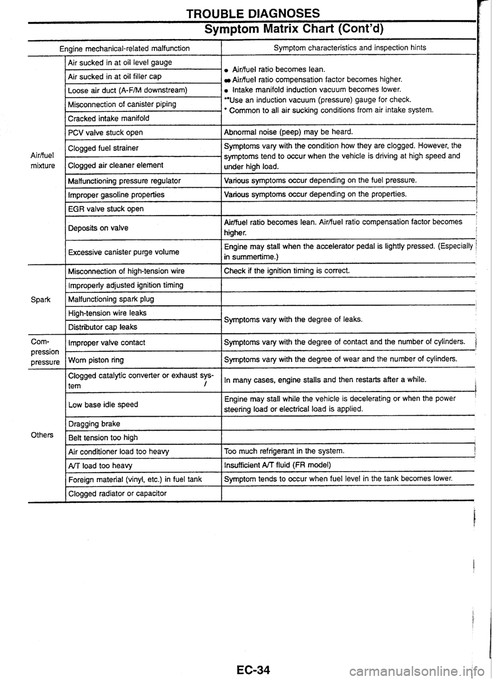
TROUBLE DIAGNOSES
Symptom Matrix Chart (Cont'd)
Engine mechanical-related malfunction I Symptom characteristics and inspection hints
Airffuel
ratio becomes lean.
Air sucked in at oil filler cap
Aidfuel ratio compensation factor becomes higher.
a Intake manifold induction vacuum becomes lower.
I Cracked intake manifold I
Misconnection of canister piping Use an induction vacuum (pressure) gauge for check.
' Common to all air sucking conditions from air intake system.
-
PCV valve stuck open
I Malfunctioning pressure regulator I Various symptoms occur depending on the fuel pressure.
Abnormal noise (peep) may
be heard.
Air/fuel
mixture
Improper gasoline properties Various
symptoms occur depending on the properties.
IEGRiale
stuck open
I
Clogged fuel strainer .
Clogged air cleaner element
Deposits on valve
r
Symptoms vary with the condition how they are clogged. However, the
symptoms tend to occur when the vehicle is driving at high speed and
under high load.
I
Air/fuel ratio becomes lean. Airfluel ratio compensation factor becomes
higher.
Excessive canister purge volume
I
Engine may stall when the accelerator pedal is lightly pressed. (Especially
in summertime.)
Misconnection of high-tension wire Check if the ignition timing
is correct. 1 Improperly adjusted ignition timing 1
Malfunctioning spark plug 1
Corn- I Improper valve contact I Symptoms vary with the degree of contact and the number of cylinders. '
High-tension wire leaks
Distributor
cap leaks Symptoms
vary with the degree of leaks.
Clogged catalytic converter or exhaust sys-
l tem , In many cases, engine stalls and then restarts after a while. I
pression I
Low base idle speed
pressure
Worn piston ring I
Engine may
stall while the vehicle is decelerating or when the power '
steering load or electrical load is applied.
Symptoms vary
with the degree of wear and the number of cylinders.
I
Air conditioner load too heavy I Too much refrigerant in the system. j
Others Dragging
brake
Belt tension too high
1
I Clogged radiator or capacitor I
ArJ load too heavy
Foreign material (vinyl, etc.) in fuel tank Insufficient A/T fluid (FR model)
Symptom tends to occur when fuel level in the tank becomes lower.
Page 44 of 230
TROUBLE DIAGNOSES
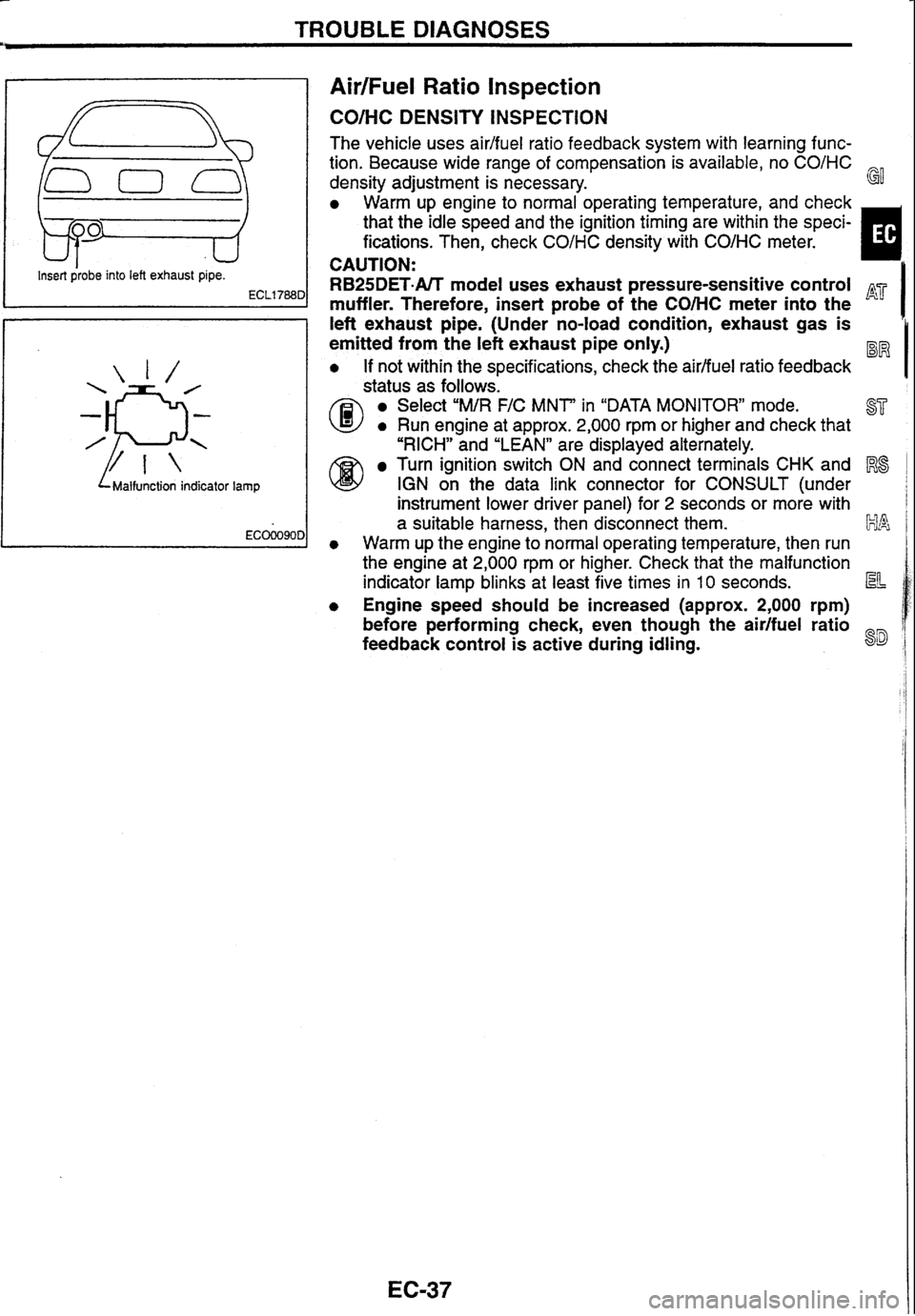
AirIFuel Ratio Inspection
Insert probe into left exhaust pipe.
ECLl788D
L Malfunction indicator lamp
CO/HC DENSITY INSPECTION
The vehicle uses aidfuel ratio feedback system with learning func-
tion. Because wide range of compensation is available, no
CO/HC
density adjustment is necessary. G!
Warm up engine to normal operating temperature, and check
that the idle speed and the ignition timing are within the speci-
fications. Then, check
CO/HC density with COIHC meter.
CAUTION:
muffler. Therefore, insert probe of the COMC meter into the
I
RB25DET-NT model uses exhaust pressure-sensitive control
I left exhaust pipe. (under -no-load condition, exhaust gas is
emitted from the left exhaust pipe only.)
a If not within the specifications, check the airlfuel ratio feedback
@status as follows.
Select "MIR FIC MNT" in "DATA MONITOR" mode.
a Run engine at approx. 2,000 rpm or higher and check that ST
I "RICH" and "LEAN" are displayed alternately.
Turn ignition switch ON and connect terminals CHK and Rs
@ IGN on the data link connector for CONSULT (under
instrument lower driver panel) for
2 seconds or more with
a suitable harness, then disconnect them. klk~
a Warm up the engine to normal operating temperature, then run
the engine at 2,000
rpm or higher. Check that the malfunction
indicator lamp blinks at least five times in
10 seconds. La=
0 Engine speed should be increased (approx. 2,000 rpm)
before performing check, even though the
air/fuel ratio
feedback control is active during idling.
8D