check oil NISSAN GT-R 1998 Service Manual
[x] Cancel search | Manufacturer: NISSAN, Model Year: 1998, Model line: GT-R, Model: NISSAN GT-R 1998Pages: 230, PDF Size: 12.66 MB
Page 20 of 230
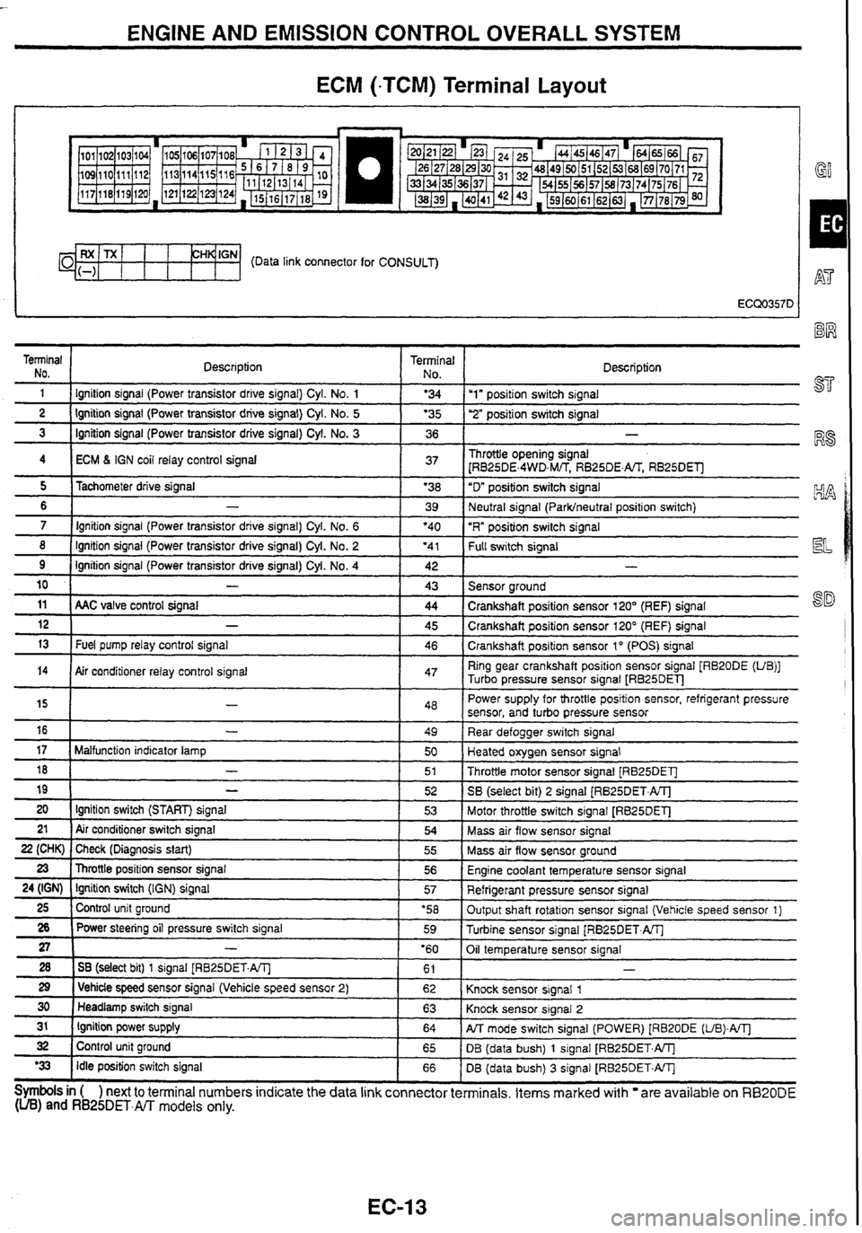
ENGINE AND EMISSION CONTROL OVERALL SYSTEM
ECM (-TCM) Terminal Layout
I GY
CH~'GN- (Data link connector for CONSULT)
Terminal NO.
1 Description Terminal 1 No I Description - - 1 I lgnition
signal (Power transistor drrve signal) Cyl. No. 1 1 '34 Iu1" positron switch signal -- ---- 2 1 Ignition signal (Power transistor drive signal) Cyl. No. 5 1 '35 1 ''2" posifion switch signal - - 3 1 Ignition signal (Power transistor drive signal) Cyl. No. 3 1 36 1 -
4 I ECM 6 IGN coil relay control signal 1 37 1 Throttle opening signal
[RB25DE.4WD,M/TS RB25DE.m RB25DEll
- - - -- - - - - 8 ( Ignition signal (Power transistor drive signal) Cyl. No. 2 ( '41 1 f-k swltch signal
5
6
7
11 ( AAC valve control signal ( 44 1 Crankshaft position sensor 120' (REF) signal
Tachometer
drive signal
-
Ignition signal (Power transistor drive signal) Cyl. No. 6
9
10
'38
39
'40
Ignition signal (Power transistor drive signal)
Cyl.
No. 4
-
12
13
"D" position switch signal
Neutral signal
(Parklneutral position switch)
"R" position switch signal
14
Symbols in ( ) next to terminal numbers indicate the data link connector terminals. Items marked with are available on RB20DE (UB) and RB25DET.m models only.
42
43
-
Fuel pump relay control signal
15
16
17
18
19
20 21
22 (CHK)
23
24 (IGN)
25
26
27
28
29
30
31
32
'33
- -
Sensor around
Air conditioner relay control signal 45
46
-
-
Malfunction indicator lamp
-
-
Ignition switch (START) signal
Air conditioner switch signal
Check (Diagnosis start)
Throttle position sensor signal
Ignition switch
(IGN) signal
Control unit ground
Power steering oil pressure switch signal
-
1 SB (select bit) 1 signal [RB25DET.A/Tl
1 Vehicle speed sensor signal (Vehicle speed sensor 2)
Headlamp switch signal
Ignition power supply
Control unit ground
Idle position switch signal Crankshaft
position sensor 120" (REF) signal
Crankshaft position sensor 1
" (POS) signal
47 Ring gear crankshaft position sensor signal [RB20DE (UB)]
Turbo pressure sensor signal
LRB25DEl-J
48
49
50
51
52
53
54
55
56
57
'58 59
'60 61
62
63
64
65
66 Power
supply for throttle position sensor, refrigerant pressure
sensor, and turbo pressure sensor
Rear defogger switch signal
Heated oxygen sensor signal
Throttle motor sensor signal [RB25DET]
SB
(select bit)
2 signal (RB25DET.ATJ
Motor throttle switch signal
[RB25DET]
Mass air flow sensor signal
Mass air flow sensor ground
Engine coolant temperature sensor signal
Refrigerant pressure sensor signal
Output shaft rotation sensor signal (Vehicle speed sensor 1)
Turbine sensor signal
[RB25DET.AlTj
Oil temperature sensor signal
Knock sensor signal
1
Knock sensor signal 2
PJT mode switch signal (POWER) [RB20DE (UB).A/Tl
DB (data bush) 1 signal [RB25DET.W
DB (data bush)
3 signal [RB25DET.W
Page 31 of 230
TROUBLE DIAGNOSES
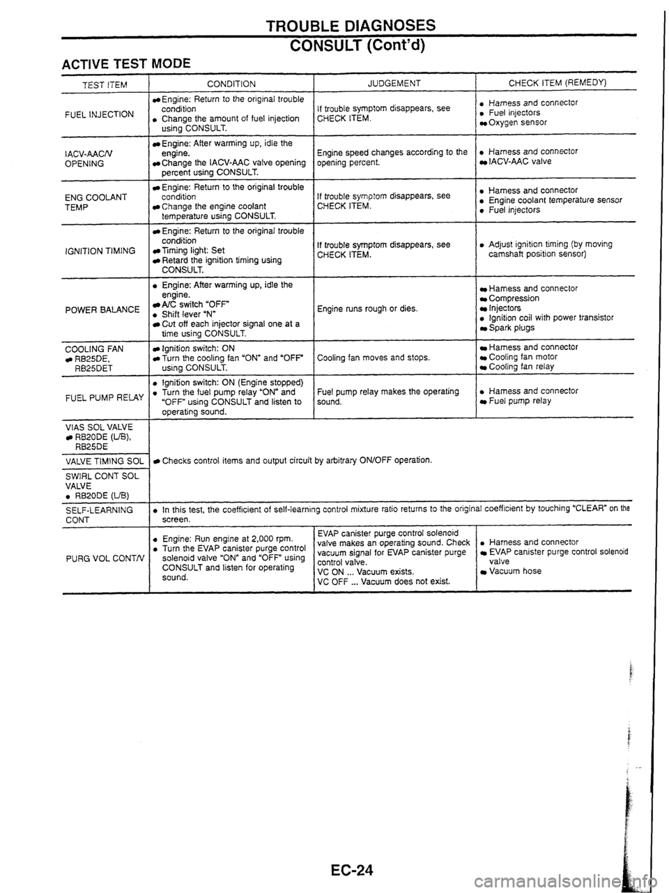
CONSULT (Cont'd)
ACTIVE TEST MODE
INJECTION I . CCohArthe amount of fuel injection
TEST ITEM
CONDITION
Engine: Return
to the original trouble
- I . Engine: After warming up, idle the
IACV-AACN
OPENING
ENG COOLANT
TEMP
IGNITION TIMING
US~~~CONSULT.
Engine: After warming up, idle the
engine.
Change the IACV-AAC valve opening
percent using CONSULT.
Engine: Return to the original trouble
conditioo
Change the engine coolant
temperature using CONSULT.
Engine: Return to the original trouble
condition
Timing light: Set Retard the ignition timing using CONSULT.
POWER BALANCE engine. A/C switch "OFF . Shift lever uNn
COOLING
FAN RB25DE, RB25DET
FUEL PUMP RELAY
VlAS SOL VALVE RB20DE (UB), RB25DE
JUDGEMENT
Cut off each injector signal one at a
time using CONSULT.
Ignition switch: ON Turn the cooling fan "ON" and "OFF
using CONSULT.
0 lgnition switch: ON (Engine stopped) . Turn the fuel pump relay "ON" and
"OFF using CONSULT and listen to
operating sound. CHECK
ITEM (REMEDY)
If trouble symptom disappears, see
CHECK ITEM. : ~,"~~,,,~scOnnectOr Oxygen sensor
Engine speed changes according to the
opening percent.
. Harness and connector IACV-AAC valve
If trouble
symp:orn disappears, see
CHECK ITEM. : Sensor 0 Fuel injectors
If trouble symptom disappears, see
CHECK ITEM. 0 Adjust ignition timing (by moving
camshaft position sensor)
Engine runs rough or dies.
Harness and connector Compression Injectors 0 lgnition coil with power transistor Spark plugs
Cooling fan moves and stops.
Hamess and connector Cooling fan motor Cooling fan relay
Fuel pump relay makes the operating
sound.
. Harness and connector Fuel pump relay
VALVE
TIMING
SOL
SWIRL CONT SOL
VALVE
0 RB20DE (UB)
SELF-LEARNING
CONT
PURG VOL CONTN
Checks control items and output circuit by arbitrary ON/OFF operation.
. In this test, the coefficient of self-learning control mixture ratio returns to the original coefficient by touching "CLEAR" on the
screen.
. Harness and connector EVAP canister purge control solenoid
valve
Vacuum hose
0 Engine: Run engine at 2,000 rpm. . Turn the EV~P canister purge control solenoid valve and using CONSULT and listen for operating
sound. EVAP
canister purge control solenoid
valve makes an operating sound. Check
vacuum signal for EVAP canister purge ~~~~~~a'cuum exists. VC OFF ... Vacuum does not exist.
Page 34 of 230
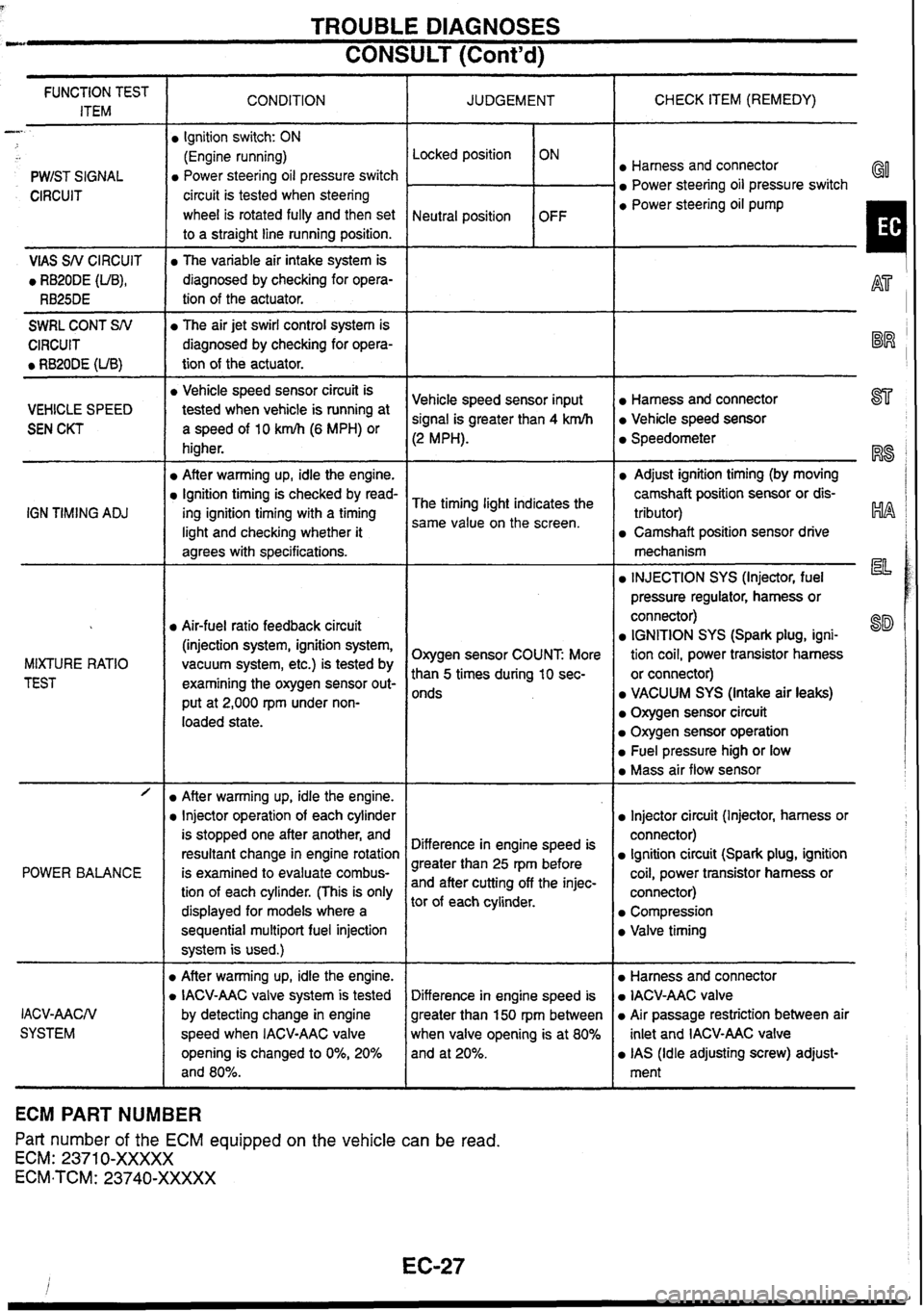
TROUBLE DIAGNOSES
CONSULT (Cont'd) --
CHECK ITEM (REMEDY)
FUNCTION TEST
ITEM CONDITION
JUDGEMENT
-
PWIST SIGNAL Locked position
Neutral position
Ignition
switch: ON
(Engine running)
Power steering oil pressure switch
circuit is tested when steering
wheel is rotated fully and then set
to a straight line running position. ON
OFF Harness and connector
Power steering oil pressure switch GO
CIRCUIT a Power steering oil pump
I VlAS SN CIRCUIT
0 RB20DE (UB),
RB25DE
The variable air intake system is
diagnosed by checking for opera-
tion of the actuator.
-
SWRL CONT SN
CIRCUIT
0 RB20DE (UB)
The air jet swirl control system is
diagnosed by checking for opera-
tion of the actuator.
-- -- -
a Vehicle speed sensor circuit is
tested when vehicle
is running at
a speed of 10 km/h (6 MPH) or
higher.
After warming up, idle the engine.
Ignition timing is checked by read-
ing ignition timing with a timing
light and checking whether it
agrees with specifications.
Harness and connector 877
Vehicle speed sensor
Vehicle
speed sensor input
signal is greater than 4 krnlh
(2 MPH).
VEHICLE SPEED
SEN CKT Speedometer
RS
Adjust ignition timing (by moving
camshaft position sensor or dis-
tributor)
HA
Camshaft position sensor drive
The
timing light indicates the
same value on the screen.
IGN
TIMING
ADJ
mechanism
la INJECTION SYS (Injector, fuel
pressure regulator, harness or
connector)
IGNITION SYS (Spark plug, igni-
tion coil, power transistor harness
or connector)
VACUUM SYS (Intake air leaks)
Oxygen sensor circuit
Oxygen sensor operation
Fuel pressure high or low
Mass air flow sensor
Air-fuel ratio feedback circuit
(injection system, ignition system,
vacuum system, etc.) is tested by
examining the oxygen sensor out-
put at 2,000
rpm under non-
loaded state. Oxygen sensor COUNT
More
than
5 times during 10 sec-
onds
MIXTURE
RATIO
TEST
- -- /
POWER BALANCE
Injector circuit (Injector, harness or
connector)
Ignition circuit (Spark plug, ignition
coil, power transistor harness or
connector)
Compression
Valve timing
After warming up, idle the engine.
Injector operation of each cylinder
is stopped one after another, and
resultant change in engine rotation
is examined to evaluate combus-
tion of each cylinder. (This is only
displayed for models where a
sequential
multipart fuel injection
system is used.)
D After warming up, idle the engine.
D IACV-AAC valve system is tested
by detecting change in engine
speed when IACV-AAC valve
opening is changed to
0%, 20%
and 80%. Difference
in engine speed is
greater than 25 rpm before
and after cutting off the injec-
tor of each cylinder.
Harness and connector
IACV-AAC valve
Air passage restriction between air
inlet and IACV-AAC valve
IAS (Idle adjusting screw) adjust-
ment
Difference
in engine speed is
greater than 150
rpm
between
when valve opening is at 80%
and at 20%.
IACV-AACN
SYSTEM
ECM PART NUMBER
Part number of the ECM equipped on the vehicle
can be read.
ECM: 2371 0-XXXXX
ECM-TCM: 23740-XXXXX
Page 40 of 230
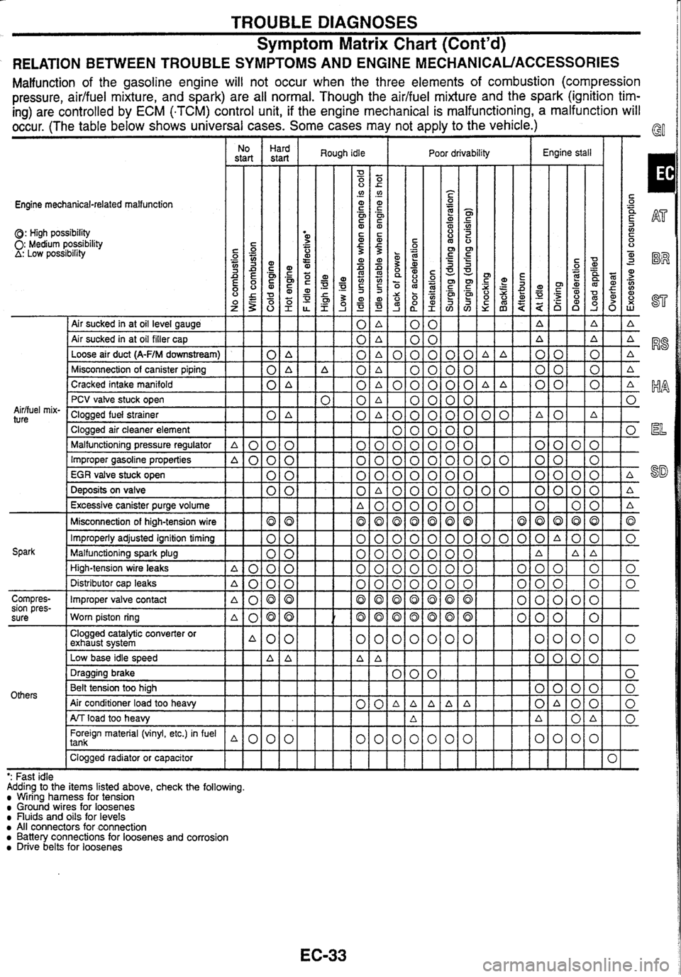
TROUBLE DIAGNOSES
Symptom Matrix Chart (Cont'd)
RELATION BETWEEN TROUBLE SYMPTOMS AND ENGINE MECHANICAUACCESSORIES
Malfunction of the gasoline engine will not occur when the three elements of combustion (compression
pressure, aidfuel mixture, and spark) are all normal. Though the
aidfuel mixture and the spark (ignition tim-
ing) are controlled by ECM
(.TCM) control unit, if the engine mechanical is malfunctioning,
a malfunction will
occur. (The table below shows universal cases. Some cases may not apply to the vehicle.)
Engine mechanical-related malfunction
0: High possibility 0: Medium possibility A: Low posstbility
I No I Hard
start start
I Air sucked in at oil level gauge
Air sucked in at oil filler cap
Loose air duct
(A-F/M downstream) 0 A
Misconnection of canister piping
0 A
Cracked intake manifold
0 A
Aidfuel
mix-
ture
PCV valve stuck open
Clogged fuel strainer
0 A
Clogged air cleaner element
Malfunctioning pressure regulator
A 0 0 0
Improper gasoline properties A000
EGR valve stuck open 0 0
Deposits on valve 0 0
Excessive canister purge volume
Misconnection of high-tension wire
Improperly adjusted ignition timing
Malfunctioning spark plug
High-tension wire leaks
A000
Spark Distributor cap leaks
A000
Compres-
Improper valve contact
sion pres-
. a080
sure Worn piston ring ~080
Others
Clogged catalytic converter or
exhaust system A00
Low base idle speed A
A
Foreign material (vinyl, etc.) in fuel 1 tank
Clogged radiator or capacitor
IIII
Rough idle I Poor drivability Engine stall
- - - - - - -- ': Fast
idle
Adding to the items listed above, check the following.
Wiring harness for tension Ground wires for loosenes nuids and oils for levels All connectors for connection Battery connections for loosenes and corrosion Drive belts for loosenes
Page 41 of 230
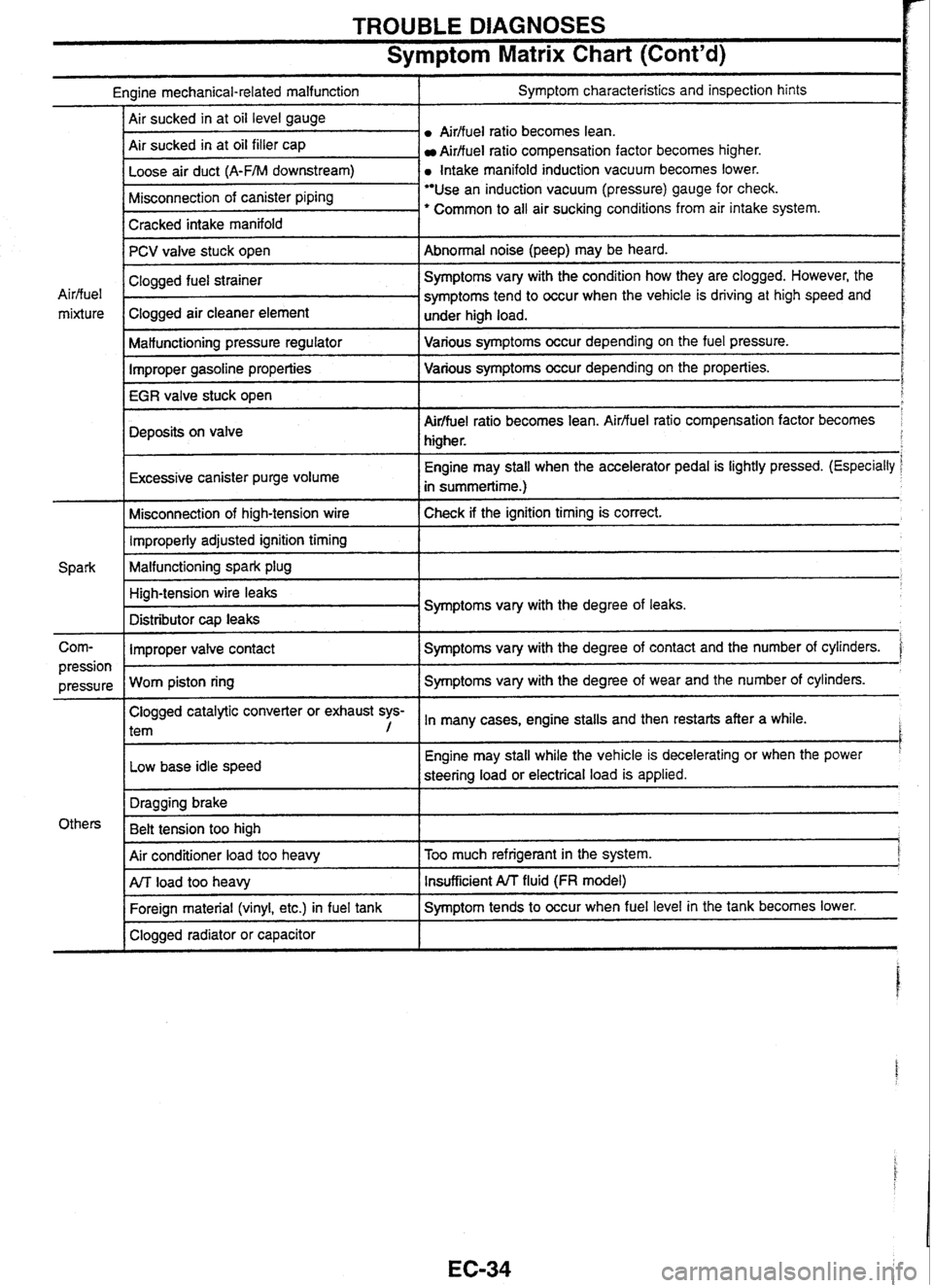
TROUBLE DIAGNOSES
Symptom Matrix Chart (Cont'd)
Engine mechanical-related malfunction I Symptom characteristics and inspection hints
Airffuel
ratio becomes lean.
Air sucked in at oil filler cap
Aidfuel ratio compensation factor becomes higher.
a Intake manifold induction vacuum becomes lower.
I Cracked intake manifold I
Misconnection of canister piping Use an induction vacuum (pressure) gauge for check.
' Common to all air sucking conditions from air intake system.
-
PCV valve stuck open
I Malfunctioning pressure regulator I Various symptoms occur depending on the fuel pressure.
Abnormal noise (peep) may
be heard.
Air/fuel
mixture
Improper gasoline properties Various
symptoms occur depending on the properties.
IEGRiale
stuck open
I
Clogged fuel strainer .
Clogged air cleaner element
Deposits on valve
r
Symptoms vary with the condition how they are clogged. However, the
symptoms tend to occur when the vehicle is driving at high speed and
under high load.
I
Air/fuel ratio becomes lean. Airfluel ratio compensation factor becomes
higher.
Excessive canister purge volume
I
Engine may stall when the accelerator pedal is lightly pressed. (Especially
in summertime.)
Misconnection of high-tension wire Check if the ignition timing
is correct. 1 Improperly adjusted ignition timing 1
Malfunctioning spark plug 1
Corn- I Improper valve contact I Symptoms vary with the degree of contact and the number of cylinders. '
High-tension wire leaks
Distributor
cap leaks Symptoms
vary with the degree of leaks.
Clogged catalytic converter or exhaust sys-
l tem , In many cases, engine stalls and then restarts after a while. I
pression I
Low base idle speed
pressure
Worn piston ring I
Engine may
stall while the vehicle is decelerating or when the power '
steering load or electrical load is applied.
Symptoms vary
with the degree of wear and the number of cylinders.
I
Air conditioner load too heavy I Too much refrigerant in the system. j
Others Dragging
brake
Belt tension too high
1
I Clogged radiator or capacitor I
ArJ load too heavy
Foreign material (vinyl, etc.) in fuel tank Insufficient A/T fluid (FR model)
Symptom tends to occur when fuel level in the tank becomes lower.
Page 47 of 230
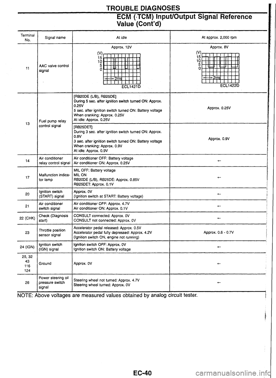
TROUBLE DIAGNOSES
ECM (-TCM) InputlOutput Signal Reference
Value (Cont'd)
d
voltages are
Terminal No. Signal name
At idle At
approx. 2,000 rpm
Approx.
12V Approx. 8V
AAC valve control
signal
[RB20DE
(UB), RB25DEl
During 5 sec. after ignition switch tumed ON: Approx. 0.25V 5 sec. after ignition switch turned ON: Battery voltage
When cranking: Approx. 0.25V At idle: Approx. 0.25V Fuel pump relay
control signal - - [RB25DETJ
During 3 sec. after ignition switch tumed ON: Approx.
0.9V
3 sec. after ignition switch tumed ON: Battery voltage
When cranking: Approx. 0.9V At idle: Approx. 0.9V
Approx. 0.9V
Air conditioner
relay control signal Air conditioner
OFF: Battery voltage
Air conditioner ON: Approx. 0.25V
MIL OFF: Battery voltage
MIL ON
RBZODE
(UB), RB25DE: Approx. 0.85V RB25DET Approx. 0.1 V
Malfunction indica-
tor lamp
lgnition switch
(START) signal
Air conditioner
switch signal Approx.
OV (Ignition
switch at START Battery voltage)
Air conditioner OFF: Approx.
4.7V Air conditioner ON: Approx. 0.1 V -
22 (CHK) Check
(Diagnosis
start)
Throttle position
sensor signal
lgnition switch
(IGN) signal CONSULT
connected: Approx. OV CONSULT not connected: Approx. OV
Accelerator pedal released: Approx. OSV Accelerator pedal fully depressed: Approx. 4.2V
(Ignition switch ON, engine not running)
lgnition switch
OFF: Approx. OV lgnition switch ON: Battery voltage Approx.
0.6 - 0.7V
24
(IGN)
Ground Approx.
OV
Power
steering oil
pressure switch
signal Steering
wheel not tumed: Approx. 4.N Steering wheel turned: Approx. OV
26
NOTE: I bove measured values obtained by analog ircuit
tester.
Page 68 of 230
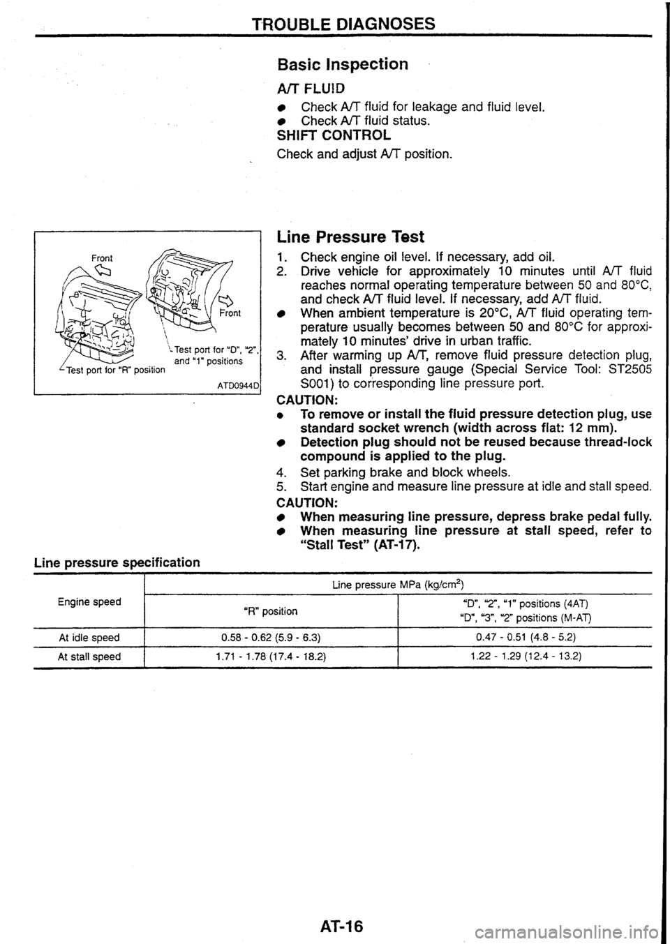
TROUBLE DIAGNOSES
n t
\-Test port for "D", "2", and "1" positions
I 'Test port for "I?" position I
Line pressure specification
Basic Inspection
Arr FLUlD
Check A/T fluid for leakage and fluid level.
Check A/T fluid status.
SHIFT CONTROL
Check and adjust A/T position.
Line Pressure Test
1. Check engine oil level. If necessary, add oil.
2. Drive vehicle for approximately 10 minutes until A/T fluid
reaches normal operating temperature between
50 and 80°C,
and check A/T fluid level. If necessary, add fluid.
When
ambient temperature is 20°C, A/T fluid operating tem-
perature
usually becomes between 50 and 80°C for approxi-
mately
10 minutes' drive in urban traffic.
3. After warming up IW', remove fluid pressure detection plug,
and install pressure gauge (Special Service Tool:
ST2505
S001) to corresponding line pressure port.
CAUTION:
0 To remove or install the fluid pressure detection plug, use
standard socket wrench (width across flat:
12 mm).
Detection plug should not be reused because thread-lock
compound is applied
to the plug.
4. Set parking brake and block wheels.
5. Start engine and measure line pressure at idle and stall speed.
CAUTION:
When measuring line pressure, depress brake pedal fully.
When measuring line pressure at stall speed, refer to
"Stall Test" (AT-17).
I p- Line pressure MPa (kg/crn2)
Engine speed
I "RW position "On, 'Z", "1" positions (4AT)
"Dm,
"3", "2" positions (M-AT)
At idle speed
At stall speed 0.58 - 0.62 (5.9 - 6.3) 0.47 - 0.51 (4.8 - 5.2)
1.71
- 1.78 (1 7.4 - 18.2) 1.22 - 1.29 (1 2.4 - 13.2)
Page 69 of 230
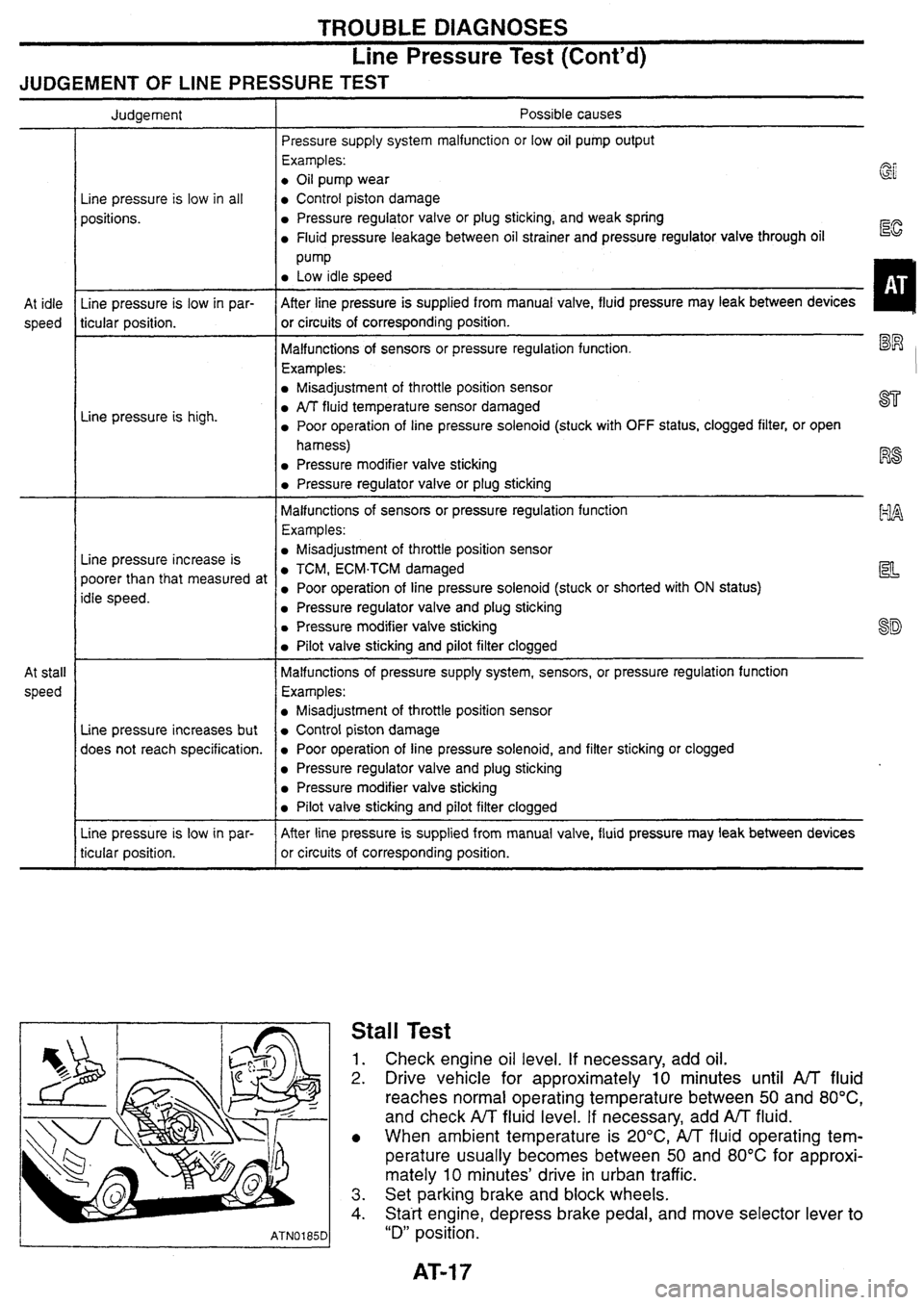
TROUBLE DIAGNOSES
Line Pressure Test (Cont'd)
JUDGEMENT OF LINE PRESSURE TEST
At idle
speed
At stall
speed Judgement
Line pressure is low in all
positions.
Line pressure is low in par-
ticular position.
Line pressure is
high.
Line pressure increase is
poorer than that measured at
idle speed.
Line pressure increases but
does not reach specification.
Line pressure is low in par-
ticular position. Possible
causes
Pressure supply system malfunction or low oil pump output
Examples:
0 Oil pump wear
Control piston damage
Pressure regulator valve or plug sticking, and weak spring
Fluid pressure leakage between oil strainer and pressure regulator valve through oil Eg
Pump
Low idle speed
After line pressure is supplied from manual valve, fluid pressure may leak between devices
or circuits of corresponding position.
1
Malfunctions of sensors or pressure regulation function. El
Examples:
Misadjustment of throttle position sensor
PJT fluid temperature sensor damaged ST
Poor operation of line pressure solenoid (stuck with OFF status, clogged filter, or open
harness)
Pressure modifier valve sticking F%
Pressure regulator valve or plug sticking
Malfunctions of sensors or pressure regulation function
Examples:
EILA
Misadjustment of throttle position sensor
TCM, ECM.TCM damaged la
Poor operation of line pressure solenoid (stuck or shorted with ON status)
Pressure regulator valve and plug sticking
Pressure modifier valve sticking
sf$
Pilot valve sticking and pilot filter clogged
Malfunctions of pressure supply system, sensors, or pressure regulation function
Examples:
Misadjustment of throttle position sensor
Control piston damage
Poor operation of line pressure solenoid, and filter sticking or clogged
Pressure regulator valve and plug sticking
Pressure modifier valve sticking
Pilot valve sticking and pilot filter clogged
After line pressure is supplied from manual valve, fluid pressure
may leak between devices
or circuits of corresponding position.
Stall Test
1. Check engine oil level. If necessary, add oil.
2. Drive vehicle for approximately 10 minutes until A/T fluid
reaches normal operating temperature between
50 and 80°C,
and check A/T fluid level. If necessary, add AfT fluid.
When ambient temperature is
20°C,
A/T fluid operating tem-
perature usually becomes between 50 and
80°C for approxi-
mately
10 minutes' drive in urban traffic.
3. Set parking brake and block wheels.
4. Statt engine, depress brake pedal, and move selector lever to
"D" position.
Page 95 of 230
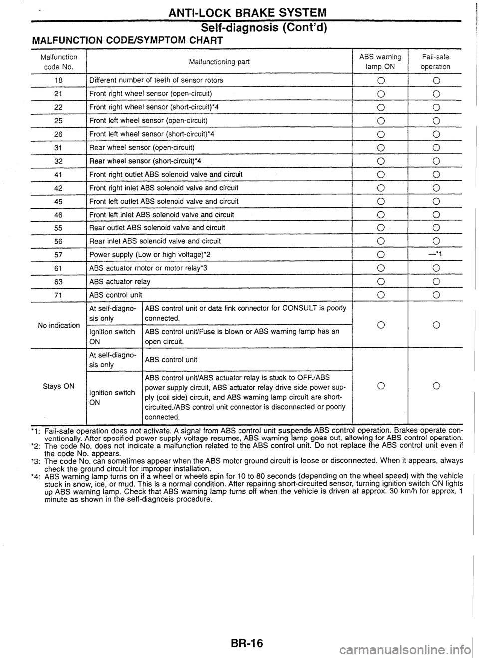
ANTI-LOCK BRAKE SYSTEM
Self-diagnosis (Cont'd)
MALFUNCTION CODEISYMPTOM CHART
Malfunction code No. Malfunctioning
part ABS warning
lamp
ON
Fail-safe
operation
18 1 Different number of teeth of sensor rotors 1010
2 1
26 I Front left wheel sensor (short-circuiQ.4 1010
- --
22
25
3 1 I Rear wheel sensor (open-circuit) 1010
Front right wheel sensor (open-circuit)
32 Rear wheel sensor (short-circuit)'4 1 0 1 0
Front right wheel sensor (short-circuit)'4
Front left wheel sensor (open-circuit)
41
I Front right outlet ABS solenoid valve and circuit 1010
0 0
0
0
0
0
- -
42
-- - -
46 Front left inlet ABS solenoid valve and circuit 0 1 0
45 Front
left outlet ABS solenoid valve and circuit
55
1 Rear outlet ABS solenoid valve and circuit 1010
Front right inlet ABS solenoid valve and circuit
56
1 Rear inlet ABS solenoid valve and circuit 1010
0
57 1 Power supply (Low or high voltage)*2 I 0 I -'I
0
0
0
I At self-diagno- ( ABS control unit or data link connector for CONSULT is poorly 1 I
61
63
At self-diagno-
I ABS control unit
sis only
ABS
actuator motor or motor relayg3
ABS
actuator relay
No indication
I I ABS control unit1ABS actuator relay is stuck to OFFJABS I Stays ON power supply circuit, ABS actuator relay drive side power sup-
lgnition switch
ply (coil side) circuit, and ABS warning lamp circuit are
short-
circuited./ABS control unit connector is disconnected or poorly
0
0
I
sis only
Ignition switch
ON
I I connected. I I
0
0
connected.
ABS control
unit1Fuse is blown or ABS warning lamp has an
open circuit.
- -- '1: Fail-safe operation does not activate. A signal from ABS control unit suspends ABS control operation. Brakes operate con-
ventionally. After specified power supply voltage resumes, ABS warning lamp goes out, allowing for ABS control operation. '2: The code No. does not indicate a malfunction related to the ABS control unit. Do not replace the ABS control unit even if the code No. appears. '3: The code No. can sometimes appear when the ABS motor ground circuit is loose or disconnected. When it appears, always
check the ground circuit for improper installation.
'4: ABS warning lamp turns on if a wheel or wheels spin for 10 to 80 seconds (depending on the wheel speed) with the vehicle
stuck in snow, ice, or mud. This is a normal condition. After repairing short-circuited sensor, turning ignition switch ON lights
up
ABS warning lamp. Check that ABS warning lamp turns off when the vehicle is driven at approx. 30 krnlh for approx. 1 minute as shown in the self-diagnosis procedure.
Page 183 of 230
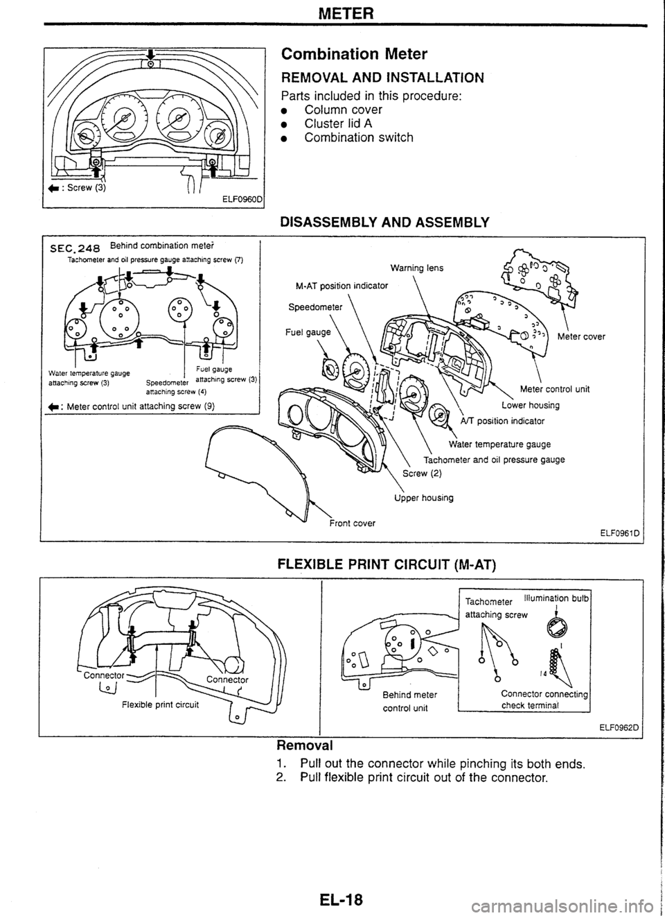
METER
Combination Meter
REMOVAL AND INSTALLATION
Parts included in this procedure:
Column cover
Cluster lid A
Combination switch
-
DISASSEMBLY AND ASSEMBLY
s EC, 248 Behind combination mete! I Tachometer and oil pressure gauge anaching screw (7)
Water tem~erature cauae I "GI yauyc - .. attaching screw (3) speedornet&
position indicator
ater temperature gauge
Tachometer
and oil pressure gauge
. . anaching screw (4)
C: Meter control unit attaching screw (9)
Upper housing cover
lit
FLEXIBLE PRINT CIRCUIT (M-AT)
I I
- Flexible
print circuit 7 r,
Tachometer Illumination bulb I
Behind meter Connector connecting
control unit
I check terminal I
I
Removal
1. Pull out the connector while pinching its both ends.
2. Pull flexible print circuit out of the connector.