clutch NISSAN GT-R 1998 Service Manual
[x] Cancel search | Manufacturer: NISSAN, Model Year: 1998, Model line: GT-R, Model: NISSAN GT-R 1998Pages: 230, PDF Size: 12.66 MB
Page 13 of 230

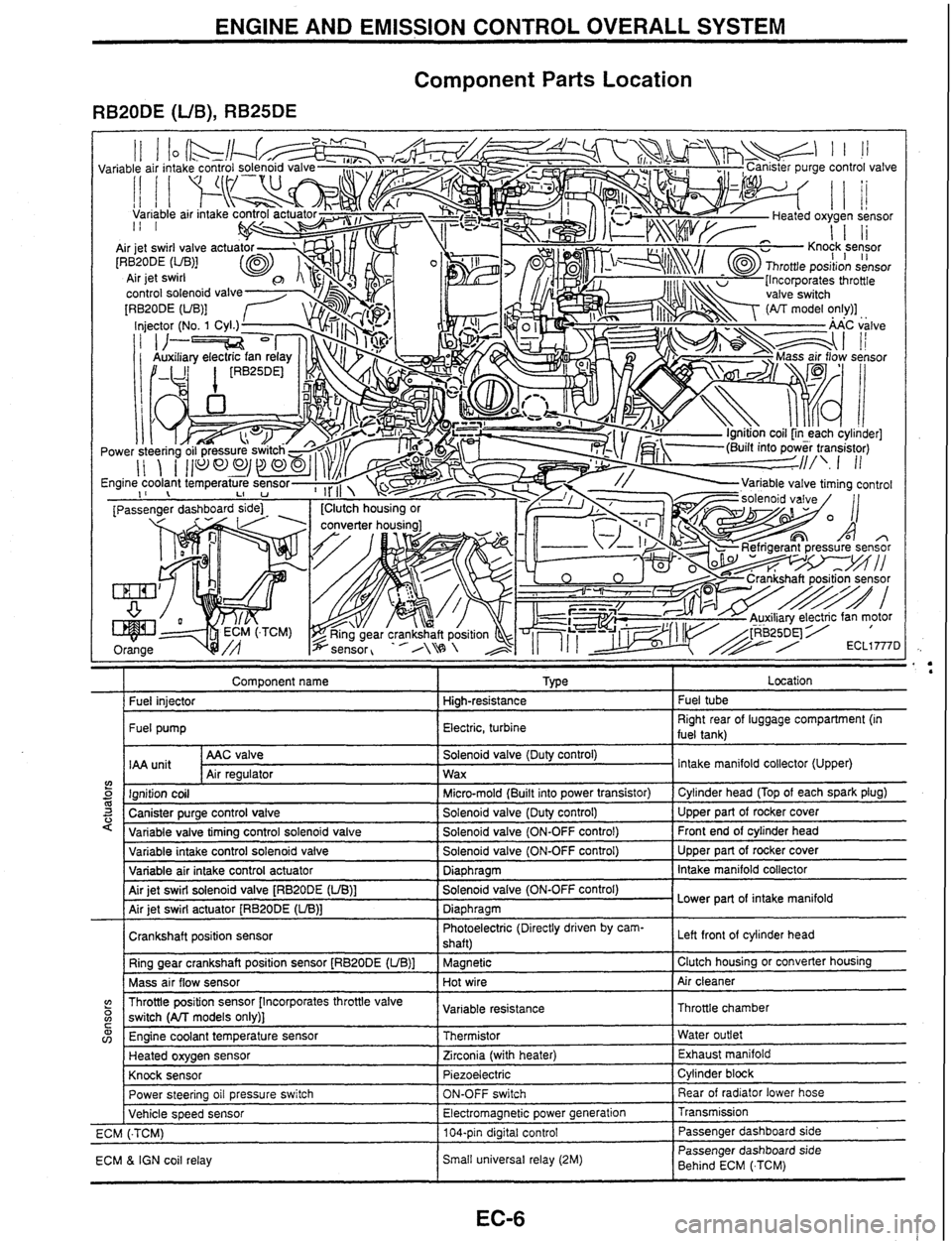
ENGINE AND EMISSION CONTROL OVERALL SYSTEM
Component Parts Location
RB20DE (UB), RB25DE
Component name I Type I Location
I Fuel iniector I Hiah-resistance I Fuel tube
I Fuel pump I Electric, turbine I Right rear of luggage compartment (in
fuel tank)
AAC valve
IAA
unit Air reaulator
5 m 3 '
Solenoid valve (Duty control)
Wax
variable intake control solenoid valve
Variable air intake control actuator
Air jet swirl solenoid valve
[RBPODE (UB)]
Air jet swirl actuator
[RB20DE (LIB)]
Crankshaft position sensor Ring gear crankshaft position sensor
[RB20DE (UB)]
Mass air flow sensor Intake
manifold collector (Upper)
Ignition coil
Canister purge control valve
Variable valve tirnina control
solenoid valve
(? o C
Solenoid valve (ON-OFF control)
Diaphragm
Solenoid valve (ON-OFF control)
Diaphragm Photoelectric (Directly driven by cam-
shaft)
Magnetic
Hot wire
w v,
Micro-mold (Built into power transistor)
Solenoid valve (Duty control)
Solenoid valve (ON-OFF control) Upper part of rocker cover
Intake manifold collector
Lower part of intake manifold
Left front
of cylinder head
Clutch housing or converter housing
Air cleaner
Throttle position sensor [Incorporates throttle valve
switch
(All models only)]
Power steering oil pressure switch
Vehicle speed sensor
ECM
(.TCM)
ECM
& IGN coil relay Cylinder head
(Top of each spark plug)
Upper part of rocker cover
Front end of cylinder head
Engine coolant temperature sensor
Heated oxygen sensor
Knock sensor Variable
resistance
ON-OFF switch
Electromagnetic power generation
104-pin digital control
Small universal relay (2M) Throttle chamber
Thermistor
Zirconia (with heater)
Piezoelectric Rear of radiator lower hose
Transmission Passenger dashboard side
Passenger dashboard side
Behind ECM
(.TCM) Water
outlet
Exhaust manifold
Cylinder block
Page 21 of 230

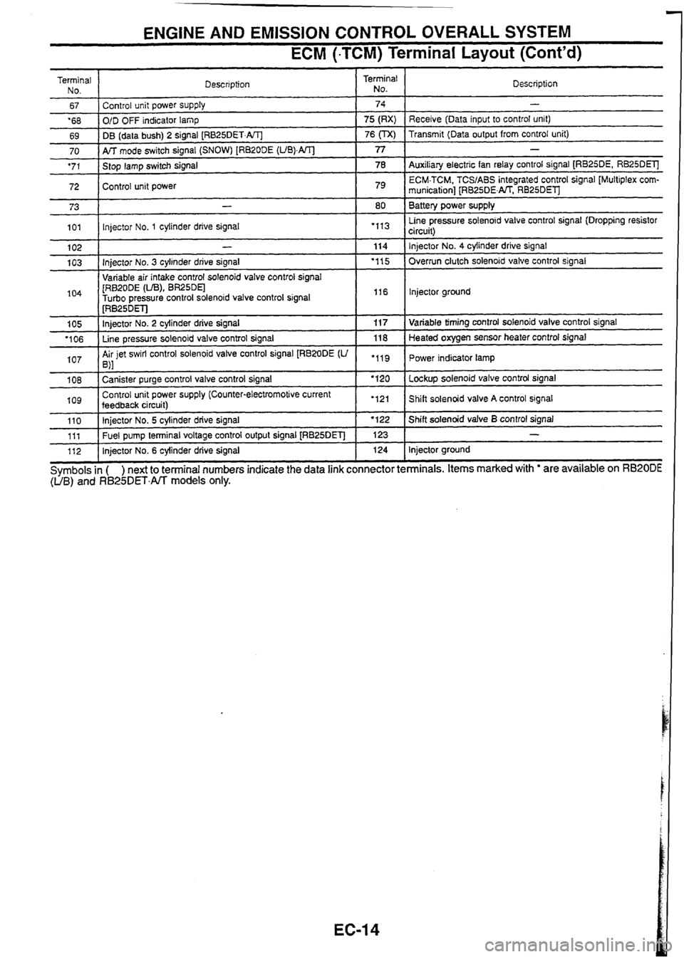
ENGINE AND EMISSION CONTROL OVERALL SYSTEM
ECM (-TCM) Terminal Layout (Cont'd)
Terminal
No.
67
'68
69 Description
70
'71
72 I
Control unit power supply
O/D OFF indicator
lamp
DB (data bush) 2 signal
[RB25DET.AIT]
73
101
104
1 [RB~ODE (LIB), BR25DEl -
Turbo oressure control solenoid valve control signal I I16 I lnjector ground
Terminal
No.
AK mode switch signal (SNOW) [RB20DE (UB).AIT]
Stop lamp switch signal
Control unit power
102
103 Description
74
75 (RX)
76
(TX)
1 I . .
-
Receive (Data input to control unit)
Transmit (Data output from control unit)
77
78
79
-
Injector No. 3 cylinder drive signal
Variable air intake control solenoid valve control
sianal
105
'106
107
-
Auxiliary electric fan relay control signal [RB25DE, RB25DElJ
ECM.TCM. TCSIABS integrated control signal [Multiplex
com-
munication] [RB25DENT. RB25DEl
Battery power supply
Line pressure solenoid valve control signal (Dropping resistor
circuit)
-
lnjector No. 1 cylinder drive signal
1 08
log
80
"I3
114
'1 15
[RB~~DET]
Injector No. 2 cylinder drive signal
Line pressure solenoid valve control signal
Air jet swirl control solenoid valve control signal
[RB20DE
(U ,\I
110 111
112 Injector No.
4 cylinder
drive signal
Overrun clutch solenoid valve control signal
"11
Canister purge control valve control signal
Control unit power supply (Counter-electromotive current
feedback
circuit) 11
7
118
.119
Symbols
in ( ) next to terminal numbers indicate the data link connector terminals. Items marked with ' are available on RB20DE (UB) and R825DET.All models only.
Injector No. 5 cylinder drive signal
Fuel pump terminal voltage control output signal
[RB25DET]
Injector No. 6 cylinder drive signal Variable
timing control solenoid valve control signal
Heated oxygen sensor heater control signal
Power indicator lamp
'120
'121 Lockup solenoid valve control signal
Shift solenoid valve
A control signal I '122
123 124 Shift solenoid valve B control signal
-
Injector ground
Page 53 of 230

AUTOMATIC TRANSMISSION
SECTION
AT
CONTENTS
SHIFT LOCK SYSTEM .................................................... 2
Component Parts Location .......................................... 2
Shift Lock Circuit Diagram ........................................... 2
Reverse Buzzer Circuit Diagram ................................. 2
TROUBLE DIAGNOSES ................................................. 3
System Description .................................................... ..3
Fail-safe Function ...................................................... ..3
................... Shift Mechanism ............. .........,,.............. .5
Clutch and Band Chart ................................................ 6
Component Parts Location .......................................... 7
........................................................... Circuit Diagram .8
Control Unit Input/Output Signal Specifications ....... .I0
Shift Pattern .............................................................. 1 3
............................................................ Shift Schedule 15
....................................................... Basic Inspection. -16
Line Pressure Test ..................................................... 16
................................................................... Stall Test 17
.................................................................. CONSULT 9
.......................................................... Self-diagnosis ..23
Symptom Chart. ........................................................ -25
Page 56 of 230

TROUBLE DIAGNOSES
Fail-safe Function (Cont'd)
SHIFT SOLENOID A, B
When a malfunctioning signal of solenoid is input to TCM and ECM-TCM, the gear is shifted as follows.
Normal Abnormal solenoid A Abnormal solenoid B Abnormal solenoid A/B Shift positions A B Gears A B Gears A I3 Gears A 8 Gears
0 0 1 st o-+x 03x - - - -
-- 0: Solenoid ON X: Solenoid OFF -: Abnormal
LINE PRESSURE SOLENOID
When a malfunctioning signal of solenoid is input to TCM and ECM-TCM, the line pressure solenoid is turned
OFF, and the line pressure is set to maximum oil pressure.
LOCK-UP SOLENOID
When a malfunctioning signal of solenoid is input to TCM and ECM.TCM, the lock-up solenoid is turned OFF,
and the lock-up
is released.
OVERRUN CLUTCH SOLENOID
When a malfunctioning signal of solenoid is input to TCM and ECM-TCM, the overrun clutch solenoid is turned
OFF, and the overrun clutch is engaged to apply the engine brake during deceleration.
MANUAL MODE SWITCH (M-AT)
When a malfunctioning signal of manual mode switch is input to TCM and ECM.TCM, the gear is controlled
with normal "D" position.
SHIFT CONTROL UNIT (Except RB20DE)
When a malfunction occurs in the shift control unit, the shift solenoid NB are turned OFF, and the gear posi-
tion
is controlled with 3rd speed.
TURBINE SENSOR (Except RB20DE)
Controlled by vehicle speed sensor 1 in the same way without turbine sensor
Page 58 of 230

TROUBLE DIAGNOSES
Clutch and Band Chart
U0.C
(Low one-
way
clutchl L&R/B
(Low and
reverse
brake)
F/O C
(Forward
clutch)
.
Remarks
PARK POSI-
TION
REVERSE POSITION
O/C
(Overrun
clutch)
*I@
'I@
'18
@
NEUTRAL
POSITION
*"
c'utch)
0
0
WC
clutch)
(Reverse
0
P
R
N
Automatic shift
0
0
FIC
(For-
ward
clutch)
0
0
0
69
0
Band servo
'4
2 Automatic shift
1 st
2nd
-3rd 4th
1 st
1. Locked in 1st
-
4th apply
0
2nd apply
0
'263
*3@
2nd
I st
2nd
0
0
0
DUAL MATIC M-ATx
3rd release
0
8
0
0
0
--
fi In Band servo I FI0.C / UOC I L&WB I
(Reverse clutch) FIC (For- WC (High
ward
clutch) clutch)
PARK POSI-
TION
REVERSE POSITION
NEUTRAL POSITION
@ 0 . . Automatic shift
0 '269 8 - -
-38 8 0
@
G3 0 Automatic shift
10 I I Automatic shift
I I I I I I I
:ch is being set in "OFF position. (D, shift is inhibited.) '2: oil pressure is applied to both 2nd "apply" side and 3rd "releasen side of band servo piston. However, brake band does not contract because oil pressure area on the "releasen side is greater than that on the "apply" side. '3: Oil pressure is applied to 4th "apply" side in condition '2 above, and brake band contracts. '4: A/T will not shift to 4th when overdrive control switch is set in "OFF position.
* 1 : O~erate when control
swil
0: Operates. a: Operates
during "progressive" acceleration.
@: Operates but does not affect power transmission. @: Operates when throttle opening is less than specification, but does not affect engine brake. fi: O~erates when throttle opening is less than specification, activating engine brake.
Page 59 of 230
![NISSAN GT-R 1998 Service Manual
TROUBLE DIAGNOSES
Component Parts Location
[M-AT (Except TCS)]
Control valve uppe:
Line pressure
solenoid Shift solenoid A
Shift solenoid B Overrun clutch
solenoid
Steering switch relay I NISSAN GT-R 1998 Service Manual
TROUBLE DIAGNOSES
Component Parts Location
[M-AT (Except TCS)]
Control valve uppe:
Line pressure
solenoid Shift solenoid A
Shift solenoid B Overrun clutch
solenoid
Steering switch relay I](/img/5/57354/w960_57354-58.png)
TROUBLE DIAGNOSES
Component Parts Location
[M-AT (Except TCS)]
Control valve uppe:
Line pressure
solenoid Shift solenoid A
Shift solenoid B Overrun clutch
solenoid
Steering switch relay I Ql Shift control unit (Except RB20DE) ?
ATN 1 985D
AT-?
Page 64 of 230

TROUBLE DIAGNOSES
Control Unit InputlOutput Signal Specifications
(Cont'd)
Terminal
No.' Operation
or measurement condition
Specifications
Total control signal
(multiple communication)
(Except
RB20DE) Refer to
EC section
("ECM.TCM or ECM Input1
Output Signal Reference Value").
I I
I Turn ignition swi?ch ON. I Battery voltage
Power supply (Backup)
Line pressure solenoid - - Turn ignition switch OFF. Battery voltage
r After engine
warm-up, depress accelerator pedal
Line pressure solenoid
(dropping resistor circuit) 5
Approx. OV
w
0.
s
Overrun clutch solenoid After engine
wan-up, release accelerator pedal.
After engine warm-up, release accelerator pedal.
After engine warm-up, depress accelerator pedal
fullv. .- >. .- 5
POWER indicator lamp (4AT)
Dual rnatic
AK waming lamp
(M-AT)
Approx. 1.5 - 3.OV
Approx. 4 - 14V
Approx. OV
When POWER indicator lamp is tumed on (W
mode switch: POWER), or dual matic warn-
ing lamp
is turned on
When
overrun clutch solenoid operates
When overrun clutch solenoid does not operate
Approx.
OV
Battery voltage Approx.
OV
When POWER indicator lamp is tumed off (NT
mode switch:Except POWER), or dual matic A/T Battery voltage
I warning lamp is turned off 1
I When vehicle is locked UD I Approx. 8 - 15V Lock-up solenoid I . .
When vehicle is not locked up I Approx. OV
When shift solenoid A operates
(Driving in 'Dln or
"D,")
When
shift solenoid A does not operate
(Driving in
"D," or "D,")
parenthesis
(
Battery voltage
Approx.
OV
Shift solenoid B
) shows the terminal No. for TCM (RB25DE ).
I
*: Each
When shift solenoid B operates
(Driving in 'Dln or
'D,")
When shift solenoid
B does not operate
(Driving in
"D,"
or
"Dd)
number Battery voltage
Approx. OV
Page 70 of 230

TROUBLE DIAGNOSES
Stall Test (Cont'd)
JUDGEMENT OF STALL SPEED
5. Depress accelerator pedal gradually while depressing brake
pedal.
6. Read stall speed quickly, and immediately release accelerator
pedal.
CAUTION: Do not
depress accelerator pedal for more than 5 seconds
when testing.
7. Move selector lever to "N" position.
8. Cool down fluid.
CAUTION:
Run engine at idle
for at least one minute.
Specification:
RB20DE 2,300 - 2,500 rpm
RB25DE 2,350 - 2,550 rpm
RB25DET 2,920 - 3,170 rpm
7 Lever position
Stall
speed status Possible causes
Forward
clutch
Forward one-way clutch
Low one-way clutch
Engine and torque converter one-way clutch
7-
0
Line pressure circuit (line pressure drop), forward clutch, low one-way clutch
and forward one-way clutch
Line pressure circuit (line pressure drop), reverse clutch and forward clutch
Forward clutch, low one-way clutch, forward one-way clutch, reverse clutch
and forward clutch
Line pressure circuit (line pressure drop), forward clutch, low one-way clutch,
forward one-way clutch, reverse clutch and
forward clutch
Clutches and brake are normal except high clutch, brake band, and overrun
It
I
0
0 0 Low & reverse brake
Reverse clutch
0: Within stall speed specification
H: Higher than stall speed specification
L: Lower than stall speed specification
0 0 0 clutch. (However, status of high clutch, brake band, and overrun clutch cannc
be confirmed by stall test.)
Page 72 of 230

TROUBLE DIAGNOSES
CONSULT (Cont'd)
SELF-DIAGNOSTIC RESULTS MODE
Diagnostic item 1 Diagnostic item is detected when ... Inspection item - -- -
I TCM does not receive vehicle speed sensor 1 signal due to
open circuit, etc.
TCM receives improper signal during driving. After ignition switch is turned ON, vehicle speed sensor 2 receives improper signal until vehicle starts to run.
VHCL
SPEED
SEN.A/T Vehicle
speed sensor 1 circuit
TCM does not receive vehicle speed sensor 2 signal due to
open circuit, etc.
TCM receives improper signal during driving.
VHCL
SPEED
SEN.MTR Vehicle
speed sensor 2 circuit
TCM detects
folfowing conditions during driving (Except N and
P positions). 0 Excessively high throttle position sensor signal voltage Excessive1 low throttle position sensor signal voltage with idle
switch OF; or full switch ON
THROTTLE
POSl
SEN
Throttle position sensor circuit
SHIFT SOLENOIDN A
SHIFT SOLENOIDN B Shift
solenoid A circuit
Shift solenoid
B circuit
Overrun clutch solenoid circuit
TIC
CLUTCH SOW
I
OVERRUN CLUTCH SN
Lock-up solenoid circuit Specified voltage is not applied to solenoid due to open and/or
short circuit.
LINE
PRESSURE SN
I Line pressure solenoid circuit
0 Excessively low supply voltage to TCM during driving
Excessively high si nal voltage of AIT fluid temperature sensor
(excessively low d fluid temperature) during driving This message is displayed only when malfunction occurs with ignition switch ON, and does not have memory func-
tion.
fluid temperature sensor circuit,
TCM power supply circuit, or
throttle position sensor power sup-
ply circuit
BATT/FLUID
TEMP SEN
ENGINE SPEED SIG
I Excessively low engine speed during driving Engine speed
signal circuit
Turbine sensor circuit
TURBINE
SENSOR
(Except
RB20DE)
SHIFT SOLENOIDN C
(Except
RB20DE)
TCM does not receive input shaft speed sensor signal due to
open circuit,
etc.
0 TCM receives improper signal during driving.
0 TCM does not receive shift solenoid A pressure detection switch
signal due to open
andfor short circuit. Shift solenoid A pressure
detection
switch circuit
MANUAL MODE SW
(Except
RB20DE)
TCM does not receive proper manual mode switch signal due to
open and/or short circuit. Manual
mode switch circuit
ENGINE BRAKE
C/U'1
(Except
RB20DE)
Shift control unit does not operate properly due to open and/or
short circuit of each
input/output signal wire.
Malfunction occurs in shift control unit. Each
signal wire circuit connected
to shift control unit
'INITIAL START*
Power supply to TCM is shut down, and self-diagnostic memory
function is canceled due to battery removal, etc.
CONTROL UNIT (RAM)
I Malfunction is detected in TCM memory (RAM) function.
CONTROL
UNIT
(ROM)
I Malfunction is detected in TCM memory (ROM) function.
'1 : Indicates shift control unit.
DATA MONITOR PROCEDURE
Refer to "CONSULT Instruction Manual - Supplement" and "CON-
SULT Service Manual
- Supplement" in details.
1. Turn ignition switch OFF.
2. Connect CONSULT connector to data link connector.
3. Turn ignition switch ON.
4. Touch "START', ''AT and "DATA MONITOR" sequentially on
CONSULT screen.
Page 74 of 230

TROUBLE
CONSU (Cont'd)
I Monitor item
Display input
signals Main
signals
-
Description Remarks
Indicates check signal (reen-
trant signal) status for TCM
control signal output.
ONIOFF
status of shift solenoid is not
changed when thermal insula-
tion or short-circuit occurs in
these valves.
Shift solenoid A SHlFT
SN A
Shift solenoid
B [ONIOFF]
OVRRUNIC SN
- [ONOFF]
Overrun
clutch solenoid
OVRRUN/C SN2
- [ONIOFF]
HOLD SW
[ONIOFFI
X
MANU MODE SW
[ONIOFFJ
NONM MODESW
[ONIOFF]
UP SW
[ONOFF]
X
DOWN SW
[ON/OFFl X
NON SHlFT SW - [ONlOFF]
Overrun
clutch solenoid
2 (Excep
RB20DE)
HOLD!SNOW
switch
A/T mode switch - SNOW mode
1 Gate side contact in mznual
mode switch
Manual
mode switch (Except
RB20DE)
- Non-gate side contact in
manual mode switch
UP (+) side contact in manual
mode switch
Non-manual
mode switch (Excepi
RB20DE)
UP switch (Except
RB20DE)
DOWN (-) side contact in
manual mode switch
DOWN
switch (Except
RB20DE)
Non-shift switch (Except
RB20DE)
Brake switch
I Stop lamp switch
BRAKE SW
[OWOFF] I
Shift solenoid A pressure detec-
tion switch
Gear position data used for
computation by TCM, is dis-
played.
Selector lever position data, A specific value used for control
used for computation by TCM, is
displayed if fail-safe is
acti-
is displayed. vated
due to error.
Vehicle speed data, used for
computation by TCM, is dis-
played.
- -- Shift solenoid valve A (P switch)
(Except
RB20DE) SHlFT
SN A
Gear position
- --- - - Selector lever position SLCT
LVR POSl
I -
VEHICLE
SPEED
[kmlh] or [mph]
I -
Vehicle speed
THROTTLE POSl
Throttle position data, used for A specific value used for control
computation by TCM, is
dis- is displayed if fail-safe is acti-
played. vated due to error.
Throttle
position
- - Control value of line pressure
solenoid valve, computed by
TCM from each input signal, is
displayed.
Control value of torque con-
verter clutch solenoid valve,
computed by TCM from each
input signal, is displayed.
Line
pressure duty LINE
PRES
DTY I
-- Torque converter clutch soienoid
valve duty TCC
SN DUTY I
Shift solenoid valve A .-control value of shift solenoid Control value
of solenoid is dis-
valve A, computed by TCM played even
if solenoid circuit is
from each input signal, is
dis- disconnected.
. - played. The
"OFF signal is displayed if
Control value of shift solenoid solenoid circuit is shorted.
Shift solenoid valve El SHIFT SN B I valve 6, computed by TCM
from each input signal, is dis-
played.
Control value of overrun clutch
solenoid valve computed by
TCM from each input signal is I OVERRUNIC SN I Overrun clutch solenoid valve
displayed.
D Control status of TCM power
>OWER
SFT
LMP
Power shift lamp
shift lamp
-- - Voltage
- Pulse
X: Applicable
-: Not applicable