turn signal NISSAN GT-R 1998 Service Manual
[x] Cancel search | Manufacturer: NISSAN, Model Year: 1998, Model line: GT-R, Model: NISSAN GT-R 1998Pages: 230, PDF Size: 12.66 MB
Page 9 of 230
ENGINE AND EMISSION CONTROL OVERALL SYSTEM
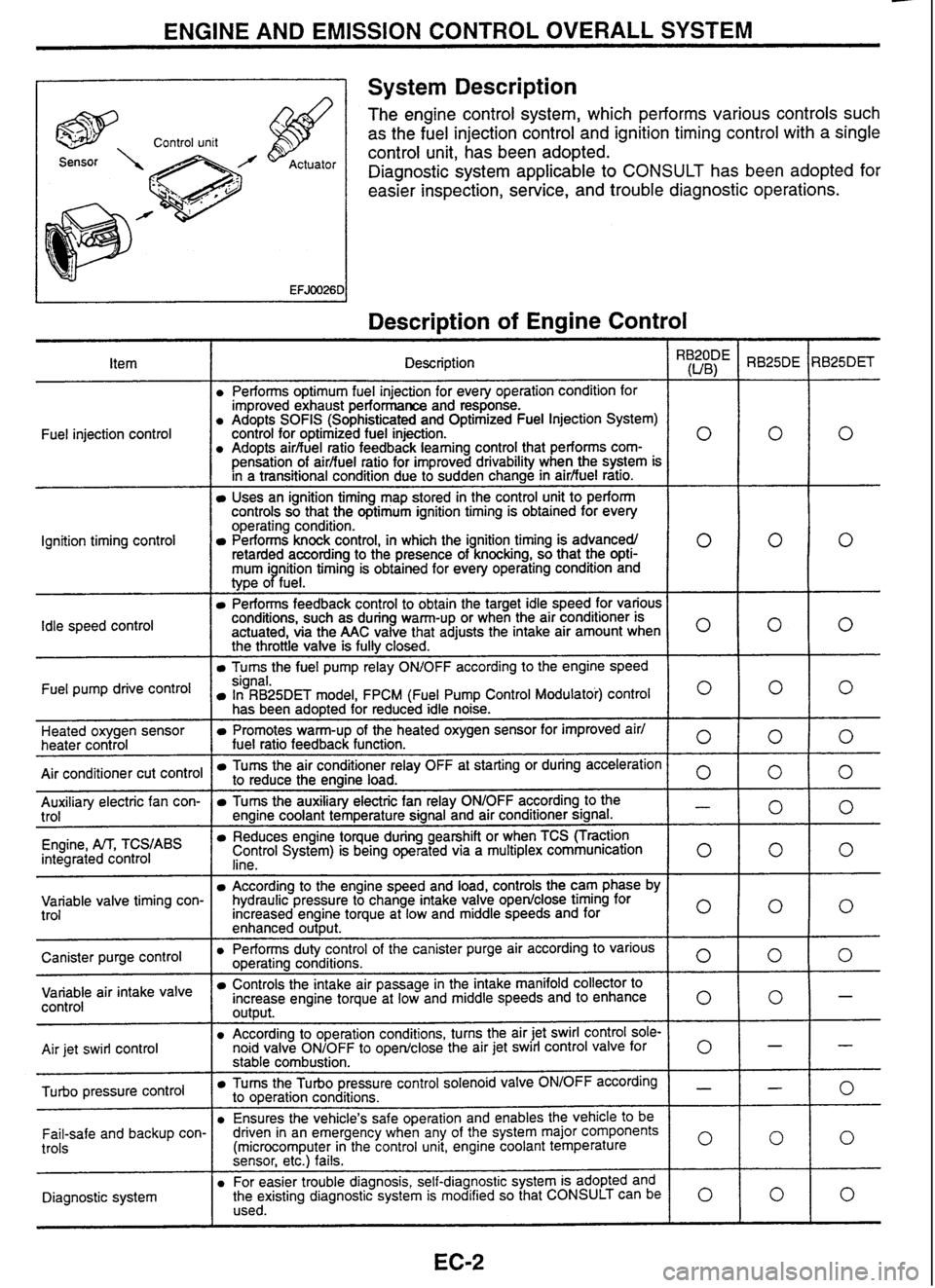
A 1 System Description
The engine control system, which performs various controls such
as the fuel injection control and ignition timing control with a single
control unit, has been adopted.
Diagnostic system applicable to
CONSULT has been adopted for
easier inspection, service, and trouble diagnostic operations.
Description of Engine Control
I
Description \,
Performs optimum fuel injection for every operation condition for
improved exhaust performance and response.
Adopts
SOFlS (Sophisticated and Optimized Fuel Injection System)
control for optimized fuel injection.
Adopts
airbuel ratio feedback
learning control that performs
com-
0
pensation of airfiuel ratio for improved drivability when the system is
in a transitional condiiion due to sudden change in
airfiuel ratro.
Uses an ignition timing map stored in the control unit to perform
controls so that the optimum ignition timing is obtained for every
operating condition.
Performs knock control, in which the ignition timing is advancedl
retarded according to the presence of knocking, so that the
opti- 0
mum i nition timing is obtained for every operating condition and
type
oPfue1.
Performs feedback control to obtain the target idle speed for various
conditions, such as during warm-up or when the air conditioner is
actuated, via the
AAC valve that adjusts the intake air amount when
O
the throttle valve is fully closed.
Turns the fuel pump relay OWOFF according to the engine speed
Fuel
injection control
Ignition timing control
Idle
speed
control
Fuel pump drive signal. In RB25DET model, FPCM (Fuel Pump Control Modulatoi) control O
has been adopted for reduced idle noise.
Heated oxygen sensor
heater control
Air conditioner cut control
Promotes warm-up of the heated oxygen sensor for improved air1
fuel ratio feedback function. 0
Tums the air conditioner relay OFF at starting or during acceleration to reduce the engine load. 0 -- Auxiliary electric fan con-
trol
Engine,
M, TCS,ABS integrated control
Tums the auxiliary electric fan relay ONIOFF according to the - engine coolant temperature signal and air conditioner signal.
Reduces engine toque during gearshift or when TCS (Traction
Control System) is being operated via a multiplex communication
lino 0
- -
Variable valve timing con-
trol According to the engine speed and load, controls the cam phase by
hydraulic pressure to change intake valve
open/close timing for
Increased engine torque at low and middle speeds and for
enhanced
out~ut.
I o I
Canister purge control air
intake valve control
Air
jet swirl control Performs duty
control of the canister purge air according to various ooeratina conditions.
0 -r-~ e-- ---
-
Controls the intake air passage in the intake manifold collector to
increase engine torque at low and middle speeds and to enhance
output. 0
According to operation conditions, turns the air jet swirl control sole-
noid valve ONIOFF to openlclose the air jet swirl control valve
for 0
pressure control
stable combustion.
Tums the Turbo pressure control solenoid valve ONIOFF according - to operation conditions.
Ensures the vehicle's safe operation and enables the vehicle
to be
Fail-safe and backup con-
trols
Diagnostic system driven
in an emergency when any of the system major components
(microcomputer in the control unit, engine coolant temperature
0
sensor, etc.) fails.
For easier trouble diagnosis, self-diagnostic system is adopted and
the existing diagnostic system is modified so that CONSULT can be
0 used.
Page 22 of 230
TROUBLE DIAGNOSES --- - - - -- -- - -
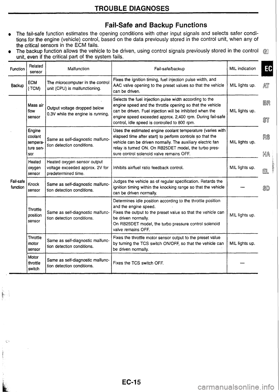
Fail-safe and Backup Functions
0 The fail-safe function estimates the opening conditions with other input signals and selects safer condi-
tions for the engine (vehicle) control, based on the data previously stored in the control unit, when any of
the critical sensors in the
ECM fails.
The backup function allows the vehicle to be driven, using control signals previously stored in the control G]
unit, even if the critical part of the system fails.
MIL indication
I
Related
sensor
Function
Backup Malfunction
Fail-safehacku p
Fixes the ignition timing, fuel injection pulse width, and
AAC valve opening to the preset values so that the vehicle
can be driven.
ECM
(-TCM)
Mass air
flow
sensor
Engine
coolant
tempera- ture sen-
sor The
microcomputer in the control
unit (CPU) is malfunctioning. MIL lights
up. A'
-- --
Selects the fuel injection pulse width according to the
engine speed and the throttle opening so that the vehicle
can be driven. Fuel injection will be inhibited when the
engine speed exceeded approx.
2,400 rpm. During fail-safe
control, idle speed is controlled to 800
rpm.
Uses the estimated engine coolant temperature (varies with
elapsed time after start) to perform controls so that the
vehicle can be driven normally. The auxiliary electric fan
relay is turned ON. On
RB25DET
model, the turbo pres-
sure control solenoid valve remains OFF.
%R
MIL lights up.
ST
Output voltage dropped below
0.3V while the engine is running.
MIL lights up.
R8 Same as self-diagnostic malfunc-
tion detection conditions.
Heated
owen
sensor Heated oxygen sensor output
voltage exceeded approx.
2V for
predetermined time.
Same as self-diagnostic malfunc-
tion detection conditions. MIL
lights up. d d Inhibits aidfuel ratio feedback control.
Judges the vehicle as of regular specification. Retards the
ignition timing within the knocking range so that the vehicle
can be driven normally.
Determines idle position according to the throttle position
and the engine speed.
Fixes the output to the preset value so that the vehicle can
be driven normally.
On
RB25DET model, the turbo pressure control solenoid
valve remains OFF.
Fail-safe
function Knock
sensor
Throttle position
sensor Same
as self-diagnostic malfunc-
tion detection conditions. MIL
lights up.
Throttle motor
sensor
--
Fixes the throttle motor sensor output to the preset value
by turning the TCS switch
ONIOFF, so that the vehicle can
Same
as self-diagnostic malfunc-
tion detection conditions. MIL
lights up.
be driven normally.
Motor
throttle
switch Same
as
self-diag
nostic
malfunc-
tion detection conditions. Fixes the
TCS switch OFF.
t.. -
Page 24 of 230
TROUBLE DIAGNOSES
Self-diagnosis (Cont'd)
I Malfunction indicator lamp
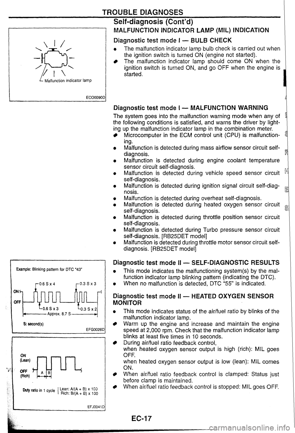
MALFUNCTiON INDICATOR LAMP (MIL) INDICATION
Diagnostic test mode I - BULB CHECK
0 The malfunction indicator lamp bulb check is carried out when
the ignition switch is turned
ON (engine not started).
The malfunction indicator lamp should come ON when the
ignition switch is turned
ON, and go OFF when the engine is
started.
Example: Blinking pattern for DTC "43"
ONh
OFF
Approx. 8.7 S
OFF (Rich)
Duty ratio in 1 cycle 1 Lean: Al(A + B) x 100 Rich: B/(A + B) x 100
EFJ0041 C
Diagnostic test mode I - MALFUNCTION WARNING
The system goes into the malfunction warning mode when any of
the following conditions is satisfied, and warns the driver by light-
ing up the malfunction indicator lamp in the combination meter.
Microcomputer in the ECM control unit (CPU) is malfunction-
1
ing.
Malfunction is detected during mass airflow sensor circuit self-
diagnosis.
Malfunction is detected during engine coolant temperature
sensor circuit self-diagnosis.
Malfunction is detected during vehicle speed sensor circuit
self-diagnosis.
Malfunction is detected during ignition signal circuit
self-diag-
nosis.
Malfunction is detected during overheat self-diagnosis.
Malfunction is detected during heated oxygen sensor circuit
self-diagnosis.
~alfunsion is detected during throttle position sensor circuit
self-diagnosis.
Malfunction is detected during Turbo pressure sensor circuit
self-diagnosis.
[RB25DET model]
Malfunction is detected during throttle motor sensor circuit self-
diagnosis.
[RB25DET model]
Diagnostic test mode I1 - SELF-DIAGNOSTIC RESULTS
0 This mode indicates the malfunctioning system(s) by the mal-
function indicator lamp blinking pattern (indicating the DTC).
0 When no malfunction is detected, DTC "55" is indicated.
Diagnostic test mode II - HEATED OXYGEN SENSOR
MONITOR
0 This mode indicates status of the aidfuel ratio by blinks of the
malfunction indicator lamp.
Warm up the engine and increase and maintain the engine
speed at 2,000 rpm. Check that the malfunction indicator lamp
blinks at least five times in
10 seconds.
During airlfuel ratio feedback control,
when heated oxygen sensor output is high (rich): MIL goes
OFF.
when heated oxygen sensor output is low (lean):
MIL comes
ON.
When aidfuel ratio feedback control is clamped: Status just
before clamp
is maintained.
When airifuel ratio feedback control is stopped: MIL goes OFF.
Page 25 of 230
TROUBLE DIAGNOSES
Self-diagnosis
(Cont'd)
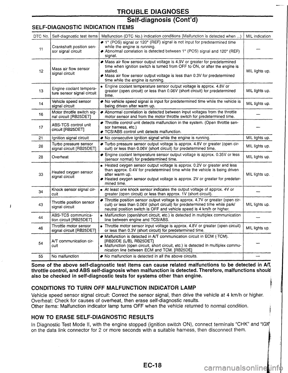
SELF-DIAGNOSTIC INDICATION ITEMS
I time while the engine is running. I
MIL indication
-
DTC No.
,,
MIL lights up. l2
Self-diagnostic test items
Crankshaft position sen-
sor signal circuit Malfunction (DTC No.)
indication conditions (Malfunction is detected when ...)
lo (POS) signal or 120" (REF) signal is not input for predetermined time
while the engine is running.
Abnohal correlation is detected between 1" (POS) signal and 120" (REF)
sianal.
Mass air flow sensor
signal circuit
MIL lights up.
Engine coo'ant tempera-
"
Mass air flow sensor output voltage is 4.9V or greater for predetermined
time when ignition switch is turned from OFF to ON, or after the engine is
stalled.
Mass air flow sensor output voltage is less than 0.3V for predetermined
Engine coolant temperature sensor output voltage is approx.
4.8V or
greater (open circuit) or less than
0.06V (short circuit) for predetermined
MIL lights up.
-
14
ABS-TCS control unit
circuit JRB25DEl-l
ture sensor signal circuit Throttle control unit detects malfunction
in the system. (Open throttle sen- sor harness, etc.)
Ignition signal circuit
Turbo pressure sensor
signal circuit
[RB25DET]
Overheat
I 1 mined time. I
time-
Vehicle speed sensor
signal circuit
Motor throttle switch sig-
nal circuit
[RB25DET]
TCS/ABS control unit detects malfunction. 1 -
I Knock sensor signal cir-
cuit
- --
No vehicle speed signal is input for predetermined time while the vehicle is
being driven after warm up.
Abnormal correlation is detected between input voltages from the throttle
motor sensor and from the motor throttle switch for predetermined time.
I
MIL lights up. Heated oxygen sensor
signal circuit
Throttle position sensor
signal circuit
No consecutive ignition signal while the engine is running.
Turbo pressure sensor output voltage is approx. 4.8V or greater (open cir-
cuit) or less than
0.06V (short circuit) for predetermined time.
Engine coolant temperature sensor output voltage is approx. 0.35V or less
(sensor normal) for predetermined time.
a Heated oxygen sensor output voltage is approx. 0.2V or greater and less
than approx.
0.4V for predetermined time while the vehicle is being driven
aner warm up. Heated oxygen sensor output voltage is approx. 2V or greater for predeter-
ABS-TCS communica- tion circuit
[RB25DET]
Throttle motor sensor
signal circuit
[RB25DET]
Afr communication cir-
cuit
MIL lights up.
lights
up.
MIL lights up.
NQ malfunction
I a At least one knock sensor indicates the output voltage of approx. 4V or
greater (open circuit) or less than approx.
1V (short circuit).
Throttle position sensor output voltage is approx. 4.7V or greater (open cir-
cuit) or less than
0.06V
(short circuit) for predetermined time while ark/
a Throttle motor sensor input voltage is approx. 418~or greater (open circuit) MIL lights up.
or less than
0.3V
(short circuit) for predetermined time. I
-
MIL liqhts up. neutral position switch is OFF and vehicle speed is 4 kdh or higher.
a Malfunction (openlshort circuit, etc.) is detected in multiplex communication
line between enaine and
TCWABS.
Malfunction is detected in PA communication circuit in ECM (-TCM).
[RBZODE (UB), RB25Dm a Malfunction (open circuit, short circuit, etc.) is detected in multiplex commu-
nication line between ECM and TCM.
[RB25DE1
-
-
No malfunction is detected in all the above circuits. I - - --
Some of the above ~elfaia~nostic test items can cause related malfunctions to be detected in M,
throttle control, and ABS seif-diagnosis when malfunction is detected. Therefore, malfunctions should
also be checked in self-diagnostic tests for systems other than engine.
CONDITIONS TO TURN OFF MALFUNCTION INDICATOR LAMP
Vehicle speed sensor signal circuit: Correct the sensor signal, then drive the vehicle at 4 km/h or higher.
Overheat: Check
for causes of overheat, then erase self-diagnostic results.
Other items: Malfunction indicator lamp turns
OFF when the vehicle returned to normal condition.
HOW TO ERASE SELF-DIAGNOSTIC RESULTS
In Diagnostic Test Mode II, with the engine stopped (ignition switch ON), connect terminals "CHK" and "IGFP
on the data link connector for
2 or more seconds with a suitable harness, then disconnect them.
Page 28 of 230
TROUBLE DIAGNOSES m
CONSULT (Cont'd)
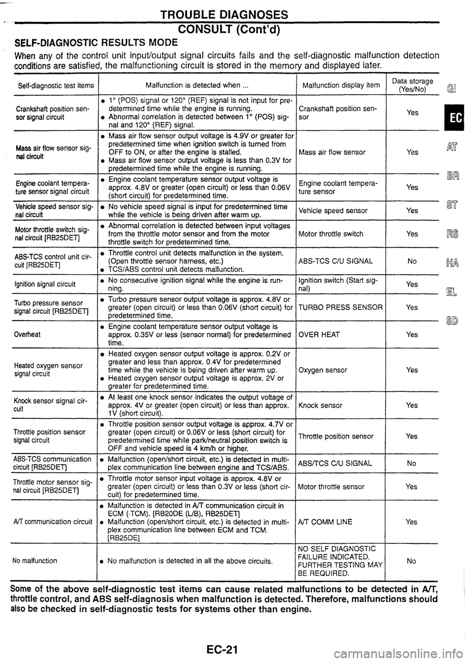
SELF-DIAGNOSTIC RESULTS MODE
When any of the control unit input/output signal circuits fails and the self-diagnostic malfunction detection
conditions
are satisfied, the malfunctioning circuit is stored in the memory and displayed later.
Self-diagnostic test items I Malfunction is detected when ... Data storage
Malfunction display item I (Yes/No,
Crankshaft position sen-
sor signal circuit
I predetermined time while the engine is running. 1 1 mm
Mass air 'low sensor sig- nal circuit
1" (POS) signal or 120" (REF) signal is not input for pre-
determined time while the engine is running.
Abnormal correlation is detected between 1" (POS) sig-
nal and 120" (REF) signal.
Mass air flow sensor output voltage is 4.9V or greater for
Vehicle speed sensor sig-
No vehicle speed signal is input for predetermined time Vehicle speed sensor I I Yes ST nal
circuit I while the vehicle is beina driven after warm UD.
predetermined time when ignition switch is turned from
OFF to ON, or after the engine is stalled.
Mass air flow sensor output voltage is less than 0.3V for
Engine coolant tempera-
ture sensor signal circuit
Crankshaft position sen-
sor
Mass air flow sensor
AT
Yes RS
-.
yes I
Engine coolant temperature sensor output voltage is
approx. 4.8V or greater (open circuit) or less than 0.06V
(short circuit) for predetermined time.
switch sig- nal circuit JRB25DETI
Engine coolant tempera- ture sensor
Abnormal correlation is detected between input voltages
from the throttle motor sensor and from the motor
throttle switch for predetermined time.
ABS-TCS control unit cir- cuit [RB25DETJ
19 L~J
Yes
--
Motor throttle switch
lgnition signal circuit
Turbo pressure sensor
signal circuit [RB25DETl
Overheat
Yes
Throttle control unit detects malfunction in the system.
(Open throttle sensor harness, etc.)
TCS/ABS control unit detects malfunction.
Heated oxygen sensor signal circuit ABS-TCS
C/U SIGNAL
No consecutive ignition
signal while the engine is run-
ning.
Turbo pressure sensor output voltage is approx. 4.8V or
greater (open circuit) or less than
0.06V (short circuit) for
predetermined time.
Engine coolant temperature sensor output voltage is
approx.
0.35V or less (sensor normal) for predetermined
time.
Yes
Heated oxygen sensor output voltage is approx. 0.2V or
greater and less than approx.
0.4V for predetermined
time while the vehicle is being driven after warm up.
Heated oxygen sensor output voltage is approx. 2V or
greater for medetermined time.
Knock cuit lgnition
switch (Start sig-
nal)
TURBO PRESS SENSOR
OVER HEAT
Oxygen sensor
Yes Yes
EL
Yes
8D
Yes
At
least one knock sensor indicates the output voltage of
approx. 4V or greater (open circuit) or less than approx.
1 V (short circuit).
Throttle position sensor
signal circuit
ABS-TCS communication
Malfunction (openlshort circuit, etc.) is detected in multi- ABSrrCS C,u circuit [RB25DETl 1 plex communication line between enaine and TCS/ABS. I
Knock sensor
Throttle position sensor output voltage is approx. 4.7V or
greater (open circuit) or
0.06V or less (short circuit) for
predetermined time while
parkheutral position switch is
OFF and vehicle
s~eed is 4
km/h or hiaher. Thronle
position sensor
Throttle motor sensor sig- nal circuit
[RB25DET] Yes
AiT communication
circuit
Yes
Throttle motor sensor input voltage is approx. 4.8V or
greater (open circuit) or less than
0.3V or less (short cir-
cuitl for
redetermined time.
No malfunction Motor
throttle sensor
Malfunction is detected in A/T communication circuit in
ECM
(.TCM).
(RB2ODE
(UB), RB25DET]
a Malfunction (opedshort circuit, etc.) is detected in multi-
plex communication line between ECM and TCM.
[RB25DE1
No malfunction is detected in all the above circuits.
A/T COMM LINE
NO SELF DIAGNOSTIC
FAILURE INDICATED.
FURTHER TESTING MAY
BE REQUIRED.
Some of the above self-diagnostic test items can cause related malfunctions to be detected in An;
throttle control, and ABS self-diagnosis when malfunction is detected. Therefore, malfunctions should
also
be checked in self-diagnostic tests for systems other than engine.
Page 29 of 230
![NISSAN GT-R 1998 Service Manual
TROUBLE DIAGNOSES
CONSULT (Contd)
DATA MONITOR MODE
ECM input
signals
Monitored item
[Unit] Main
signals Remarks
Description
lndicates the engine speed computed
from the POS signal (l NISSAN GT-R 1998 Service Manual
TROUBLE DIAGNOSES
CONSULT (Contd)
DATA MONITOR MODE
ECM input
signals
Monitored item
[Unit] Main
signals Remarks
Description
lndicates the engine speed computed
from the POS signal (l](/img/5/57354/w960_57354-28.png)
TROUBLE DIAGNOSES
CONSULT (Cont'd)
DATA MONITOR MODE
ECM input
signals
Monitored item
[Unit] Main
signals Remarks
Description
lndicates the engine speed computed
from the POS signal (lo signal) of the
camshaft position sensor.
When the engine is stopped, a certain
value is indicated.
When the engine coolant temperature
sensor is open or short-circuited, ECM
enters fail-safe mode. The engine coolant
temperature determined by the ECM is
displayed.
The signai voltage of the mass air flow
0 sensor is displayed.
The engine coolant temperature (deter-
mined by the signal voltage of the engine
0 coolant temperature sensor) is displayed.
-
MAS AIRiFL SE [V]
The signal voltage of the oxygen sensor
is displayed.
02
SEN [V]'
0 After turning ON the ignition switch, "RICH" is displayed until air-fuel mixture
ratio feedback control begins.
When the air-fuel ratio feedback is
clamped, the value just before the clamp-
ing is displayed continuously.
MiR
F/C MNT*
[RICH/LEAN] Display of oxygen sensor signal during
air-fuel ratio feedback control:
RICH
... means the mixture became
"rich", and control is being affected
toward a leaner mixture.
LEAN
... means the mixture became
"lean", and control is being affected
toward
a rich mixture.
The vehicle speed computed from the
vehicle speed sensor signal is displayed. VHCL SPEED SE [krn/h] or [mph]
The power supply voltage of ECM is dis-
played. I BATTERY VOLT [V]
THRTL POS SEN [V] The throttle position sensor signal volt-
age is displayed.
Throttle motor sensor output voltage Approx. 4.6V THRTL POS SE2 [V] 0 RB25DET
TURBO BOOST
SENSOR
RB25DET
Turbo pressure sensor output voltage 0 Approx. 2.7V
Indicates [ON/OFF] condition from the After starting the engine, [OFF] is dis-
0 starter signal. played regardless of the starter signal.
lndicates [ON/OFF] condition from the 0 throttle position sensor signal.
-
START SIGNAL
[ON/OFF]
CLSD THUP SW
[0
N/O
FF]
0 lndicates [ON/OFF] condition of the air
conditioner switch as determined by the
air conditioner sianal. AIR COND SIG
[ON/OFF]
lndicates [ON/OFFj condition from the
parldneutral position switch signal.
PiN
POSl SW [ONIOFF)
PW/ST SIGNAL
[ONIOFF]
LOAD SIGNAL
[ON/OFF]
lndicates [ON/OFfl condition from the
electrical load signal
andlor lighting
switch.
ON ... rear defogger is operating.
OFF ... rear defogger is not operating.
NOTE: Any monitored item that does not match the vehicle being diagnosed is deleted from the display automatically. *: Models with three way catalyst.
Page 31 of 230
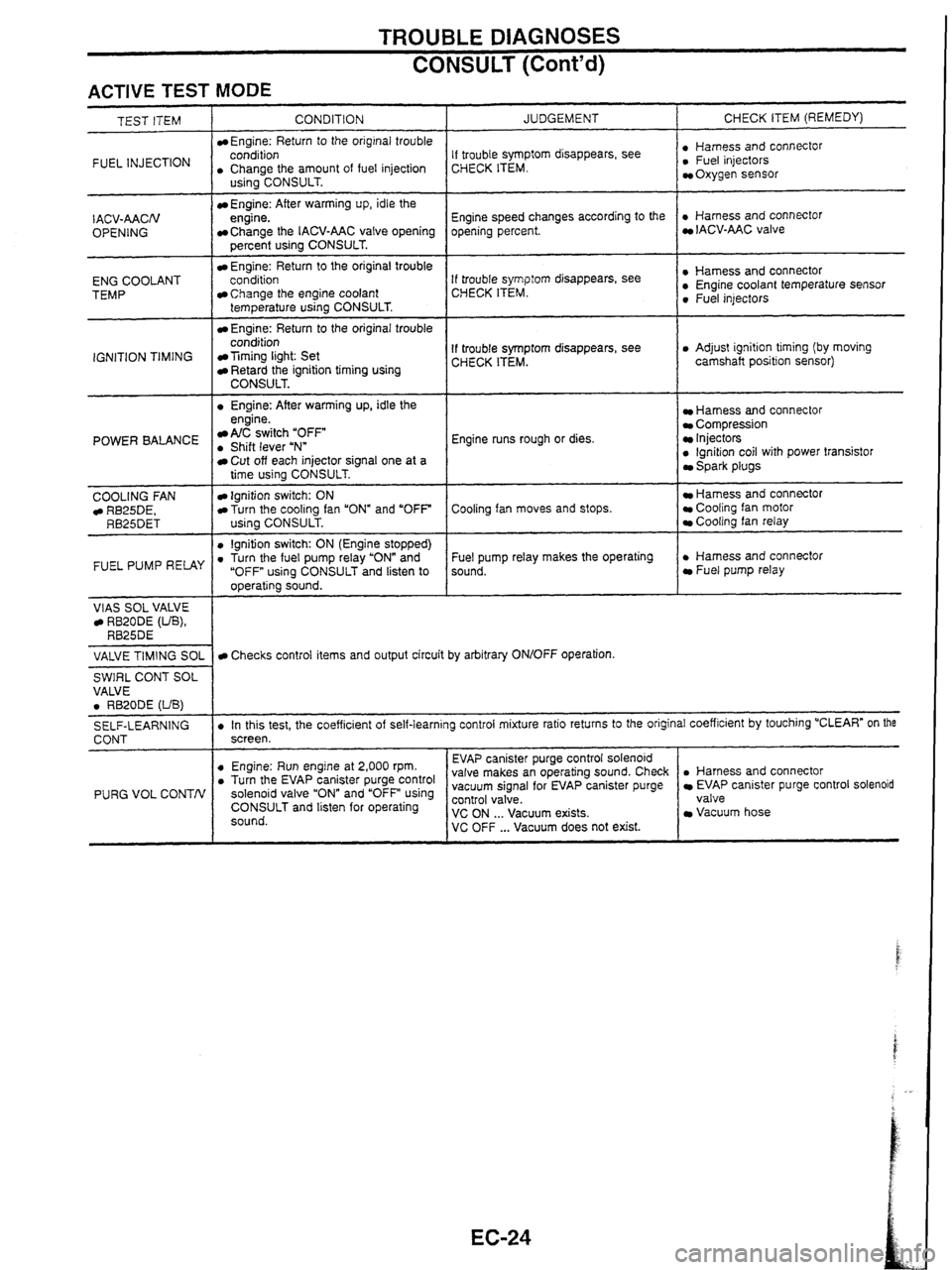
TROUBLE DIAGNOSES
CONSULT (Cont'd)
ACTIVE TEST MODE
INJECTION I . CCohArthe amount of fuel injection
TEST ITEM
CONDITION
Engine: Return
to the original trouble
- I . Engine: After warming up, idle the
IACV-AACN
OPENING
ENG COOLANT
TEMP
IGNITION TIMING
US~~~CONSULT.
Engine: After warming up, idle the
engine.
Change the IACV-AAC valve opening
percent using CONSULT.
Engine: Return to the original trouble
conditioo
Change the engine coolant
temperature using CONSULT.
Engine: Return to the original trouble
condition
Timing light: Set Retard the ignition timing using CONSULT.
POWER BALANCE engine. A/C switch "OFF . Shift lever uNn
COOLING
FAN RB25DE, RB25DET
FUEL PUMP RELAY
VlAS SOL VALVE RB20DE (UB), RB25DE
JUDGEMENT
Cut off each injector signal one at a
time using CONSULT.
Ignition switch: ON Turn the cooling fan "ON" and "OFF
using CONSULT.
0 lgnition switch: ON (Engine stopped) . Turn the fuel pump relay "ON" and
"OFF using CONSULT and listen to
operating sound. CHECK
ITEM (REMEDY)
If trouble symptom disappears, see
CHECK ITEM. : ~,"~~,,,~scOnnectOr Oxygen sensor
Engine speed changes according to the
opening percent.
. Harness and connector IACV-AAC valve
If trouble
symp:orn disappears, see
CHECK ITEM. : Sensor 0 Fuel injectors
If trouble symptom disappears, see
CHECK ITEM. 0 Adjust ignition timing (by moving
camshaft position sensor)
Engine runs rough or dies.
Harness and connector Compression Injectors 0 lgnition coil with power transistor Spark plugs
Cooling fan moves and stops.
Hamess and connector Cooling fan motor Cooling fan relay
Fuel pump relay makes the operating
sound.
. Harness and connector Fuel pump relay
VALVE
TIMING
SOL
SWIRL CONT SOL
VALVE
0 RB20DE (UB)
SELF-LEARNING
CONT
PURG VOL CONTN
Checks control items and output circuit by arbitrary ON/OFF operation.
. In this test, the coefficient of self-learning control mixture ratio returns to the original coefficient by touching "CLEAR" on the
screen.
. Harness and connector EVAP canister purge control solenoid
valve
Vacuum hose
0 Engine: Run engine at 2,000 rpm. . Turn the EV~P canister purge control solenoid valve and using CONSULT and listen for operating
sound. EVAP
canister purge control solenoid
valve makes an operating sound. Check
vacuum signal for EVAP canister purge ~~~~~~a'cuum exists. VC OFF ... Vacuum does not exist.
Page 37 of 230

TROUBLE DIAGNOSES
Symptom Matrix Chart (Cont'd)
Sensor-related problems I Symptom characteristics and ins~ection hints
Open Engine
will not start when either REF signal circuit or POS signal circuit is open.
Neither fuel system nor ignition system outputs control signals.
Crankshaft position sensor
(POS, REF) Instanta-
neous break Symptoms
vary with the break time and the vehicle's driving conditions. Light
shock or surging will occur while the vehicle is being driven, and the engine will
stall at idle speed.
Ring gear crankshaft position
sensor
[RB20DE
(UB)]
Signal
Mass air flow sensor Open
Open
High output
Low output I Aidfuel
ratio becomes lean. Dirty hot wire or air entering the system could be the
cause. No
airfluel ratio compensation
is carried out during lean bum status. Drivability
may be affected.
Enters fail-safe mode. Driving under
2,400 rpm is allowed.
Airlfuel
ratio becomes rich. Black smoke may be noted. Poor contact at the
ground could be the cause.
Engine coolant temperature sen-
sor Open
Open
Opedshort
High resis-
tance
Low resis-
tance
Opedshort
Heated oxygen sensor
I
Airlfuel ratio becomes over-rich.
Same symptom as when signal wire is open.
Enters fail-safe mode. Malfunction indicator lamp comes ON. Ordinary driving is
allowed. Problems tend to occur when engine is cold or engine coolant tempera-
ture
is high.
Detects low engine coolant temperature. Problems tend to occur after engine
warm-up.
Detects high engine coolant temperature. Problems tend to occur when engine is
cold.
Base
aidfuel ratio is used.
lgnition timing is retarded within the knock control range. Lack of power may be
OpedShort
I noted.
Knock sensor lgnition
timing is retarded within the knock control range. Lack of power may be
High
Output
(noted.
Low output
1 lgnition timing may not be retarded when knock is detected.
Vehicle speed sensor
Throttle position sensor
Opedshort
Opedshort
Unstable out-
put
Poor adjust-
ment
Open
Turbo pressure sensor
(TE) Fuel
cut time becomes-shorter, or no fuel cut is observed.
Base idle speed is used. Fuel injection is not increased during acceleration.
AIT shift point changes for AfF vehicles.
Unnecessary cut-in fuel injection could be the cause. Poor contact at the ground
or control unit could be the cause.
ldle judgment is "OFF while idling. Condition returns
normal by turning the igni-
tion switch ON and OFF repeatedly.
Turbo pressure is judged zero. No remarkable malfunction will be detected.
Refrigerant pressure is judged high. ldle speed remains high while the air condi-
tioner is ON.
Refrigerant pressure sensor
Short Refrigerant pressure
is judged low. ldle speed remains low while the air condi-
tioner is ON.
lgnition switch (IGN)
lgnition switch (START)
Air conditioner switch Open
Engine
will not start because neither fuel system nor ignition system outputs con-
trol signals.
Engine starts in normal condition. Engine may not start when temperature is
extremefy
low.
Air conditioner will not operate. No other malfunction will be noted.
Park/neutral
position switch is judged "OFF. Target engine speed for cold engine
in
N or P position is reduced.
ParWneutral position switch is judged
"0N"I Fast Jdle is effective when the engine
is cold and the gear is in other than N and P posrtlons. Vehrcle excessrvely
creeps.
Open
Open
Parklneutral
position
switch
Short
Power steering oil pressure
switch Open
Engine may
stall when the steering wheel is turned while the vehicle is standstill
and the accelerator pedal is lightly pressed, or when the steering wheel is turned
Electrical load switch Short
Open
Open/short
Multiplex communication line
- -- during deceleration. '
Power steering switch is judged 'ON." Value will be compensated constantly.
Idle speed drops so that the engine can stall when electrical load is applied.
Torque reduction control is not performed. Therefore,
shift shock becomes
greater.
- -- -- -- -- Engine will not start because neither fuel system nor ignition system outputs con-
trol signals.
Open
Control unit power supply
- -- - - --- - - - - - O~edshort I Same symptoms as when sensor harness is open.
Sensor ground -- - Poor contact
Water intru-
sion - -- - - - - - -- -- In case of poor contact, the connector fitting may be loose. In case of water
intrusion, the engine stalls and become inoperative for a while. The engine may restart soon in some cases.
Control unit
and connector
Page 46 of 230

TROUBLE DIAGNOSES
P ECM (aTCM) InputDutput Signal Reference
Value
SIGNAL VOLTAGES MEASURED WITH OSCILLOSCOPE AND CIRCUIT TESTER
- Signal voltages measured at ECM (-TCM) terminals (terminals for engine control) with a circuit tester and
example of waveforms displayed on an oscilloscope are shown below.
For signal terminals for A/T control, refer to "AIT Trouble Diagnosis" in AT section.
Measured data are affected by many factors such as irregularity of parts, vehicle history, operating
conditions, environment, service status, and measuring instruments and methods.
Terminal
No.
RX / TX
Signal name
I nition signal 8 ower transistor
drive signal)
CH~~"N
ECM & IGN coil
relay control signal (Data
link connector for CONSULT)
Tachometer drive
signal
NOTE: Above
At idle
When cranking: Approx. 0.1 2V
At idle: Approx. 0.1 V
?pprox. 1V
,During approx. 1.5
sec. after ignition switch turned OFF: 4pprox. 1 V 1.5 sec. after ignition switch turned OFF: Battery voltage)
:RB20DE
(UB),
RB25DEJ
Approx.
1.2V
:RB25DET]
Approx.
7.2V At
approx. 2,000 rpm
Approx. 0.15
- 0.25V
Approx. 3V
voltages are measured values obtained by analog circuit tester.
EC-39
Page 47 of 230
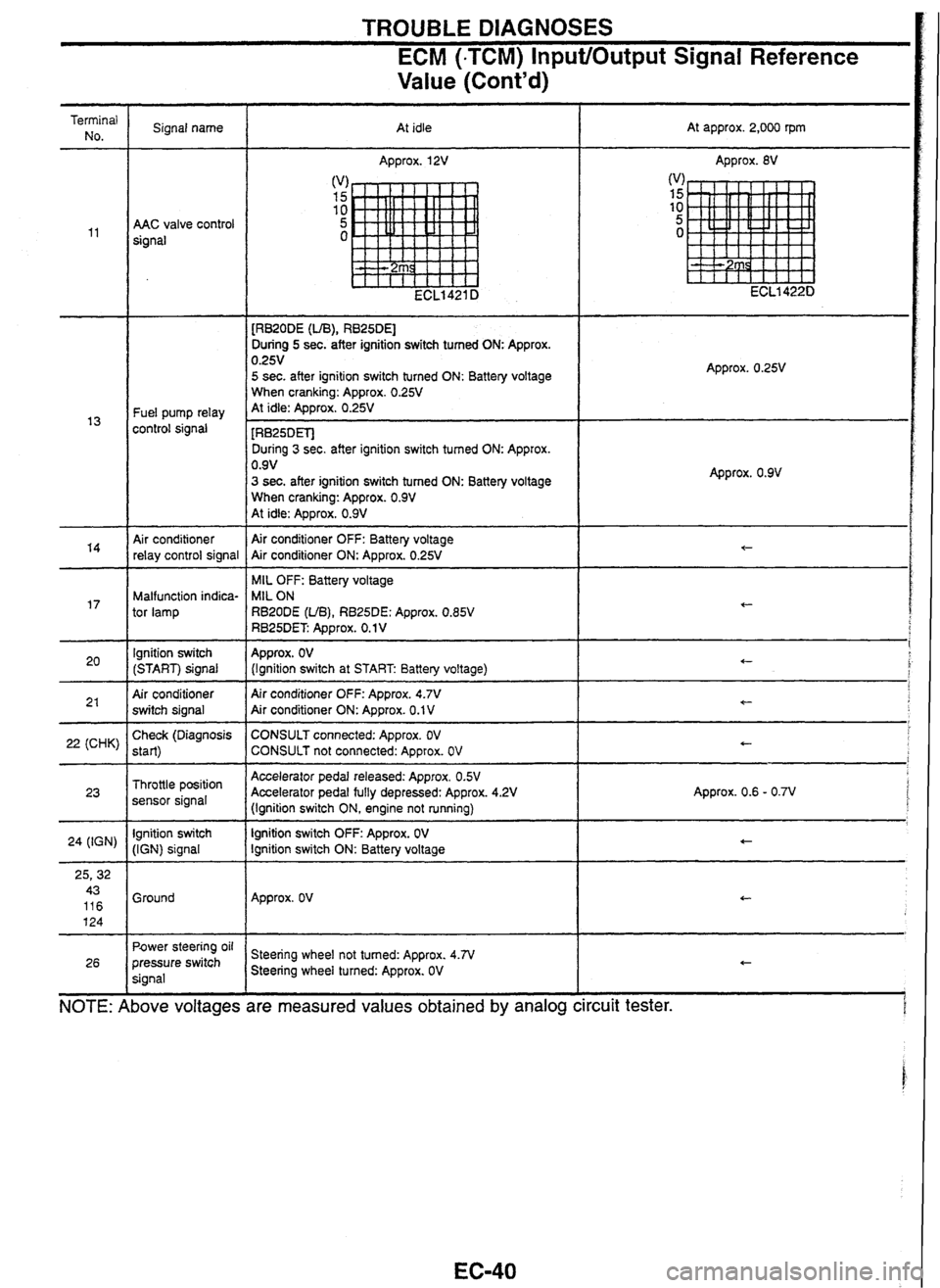
TROUBLE DIAGNOSES
ECM (-TCM) InputlOutput Signal Reference
Value (Cont'd)
d
voltages are
Terminal No. Signal name
At idle At
approx. 2,000 rpm
Approx.
12V Approx. 8V
AAC valve control
signal
[RB20DE
(UB), RB25DEl
During 5 sec. after ignition switch tumed ON: Approx. 0.25V 5 sec. after ignition switch turned ON: Battery voltage
When cranking: Approx. 0.25V At idle: Approx. 0.25V Fuel pump relay
control signal - - [RB25DETJ
During 3 sec. after ignition switch tumed ON: Approx.
0.9V
3 sec. after ignition switch tumed ON: Battery voltage
When cranking: Approx. 0.9V At idle: Approx. 0.9V
Approx. 0.9V
Air conditioner
relay control signal Air conditioner
OFF: Battery voltage
Air conditioner ON: Approx. 0.25V
MIL OFF: Battery voltage
MIL ON
RBZODE
(UB), RB25DE: Approx. 0.85V RB25DET Approx. 0.1 V
Malfunction indica-
tor lamp
lgnition switch
(START) signal
Air conditioner
switch signal Approx.
OV (Ignition
switch at START Battery voltage)
Air conditioner OFF: Approx.
4.7V Air conditioner ON: Approx. 0.1 V -
22 (CHK) Check
(Diagnosis
start)
Throttle position
sensor signal
lgnition switch
(IGN) signal CONSULT
connected: Approx. OV CONSULT not connected: Approx. OV
Accelerator pedal released: Approx. OSV Accelerator pedal fully depressed: Approx. 4.2V
(Ignition switch ON, engine not running)
lgnition switch
OFF: Approx. OV lgnition switch ON: Battery voltage Approx.
0.6 - 0.7V
24
(IGN)
Ground Approx.
OV
Power
steering oil
pressure switch
signal Steering
wheel not tumed: Approx. 4.N Steering wheel turned: Approx. OV
26
NOTE: I bove measured values obtained by analog ircuit
tester.