warning NISSAN GT-R 1998 Service Manual
[x] Cancel search | Manufacturer: NISSAN, Model Year: 1998, Model line: GT-R, Model: NISSAN GT-R 1998Pages: 230, PDF Size: 12.66 MB
Page 5 of 230

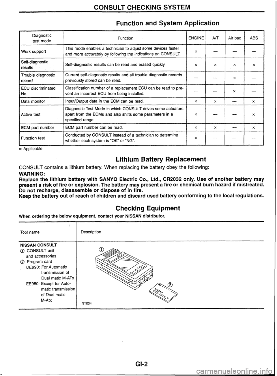
CONSULT CHECKING SYSTEM
Function and System Application
Diagnostic test mode
Work support
Self-diagnostic results
Trouble diagnostic record Function
This mode enables a technician to adjust some devices faster
and more accurately by following the indications on CONSULT.
ECU discriminated
No.
Data monitor
I I whether each system is "OK" or 'NG". lxH-1-
Conducted by CONSULT instead of a technician to determine
Function test Self-diagnostic
results can be read and erased quickly.
Current self-diagnostic results and all trouble diagnostic records
previously stored can be read.
Active test
ECM part number
L x: Applicable ENGINE
x
Classification
number of a replacement ECU can be read to pre-
vent an incorrect ECU from being installed.
InputIOutput data in the ECM can be read.
Lithium Battery Replacement
x
Diagnostic Test Mode in which CONSULT drives some actuators
apart from the
ECMs and also shifts some parameters
in a
specified range.
ECM part number can be read.
CONSULT contains a lithium battery. When replacing the battery obey the following:
WARNING:
Replace the lithium battery with SANYO Electric Co., Ltd.,
CR2032 only. Use of another battery may
present
a risk of fire or explosion. The battery may present a fire or chemical burn hazard if mistreated.
Do not recharge, disassemble or dispose of in fire.
Keep the battery out of reach of children and discard used battery conforming to the local regulations.
AfT
-
-
x
Checking Equipment
x
-
x
x
When ordering the below equipment, contact your NlSSAN distributor. Air
bag
-
-
-
x
!
Tool name ABS
-
x
X
-
x
NISSAN CONSULT
@ CONSULT unit
and accessories
@ Program card
UE990: For Automatic
transmission of
Dual
rnatic M-ATx
EE980: Except for Auto-
matic transmission
of Dual
matic
M-Atx
x
-
--
X
-
Description
-
x
-
-
x
x
Page 24 of 230

TROUBLE DIAGNOSES
Self-diagnosis (Cont'd)
I Malfunction indicator lamp
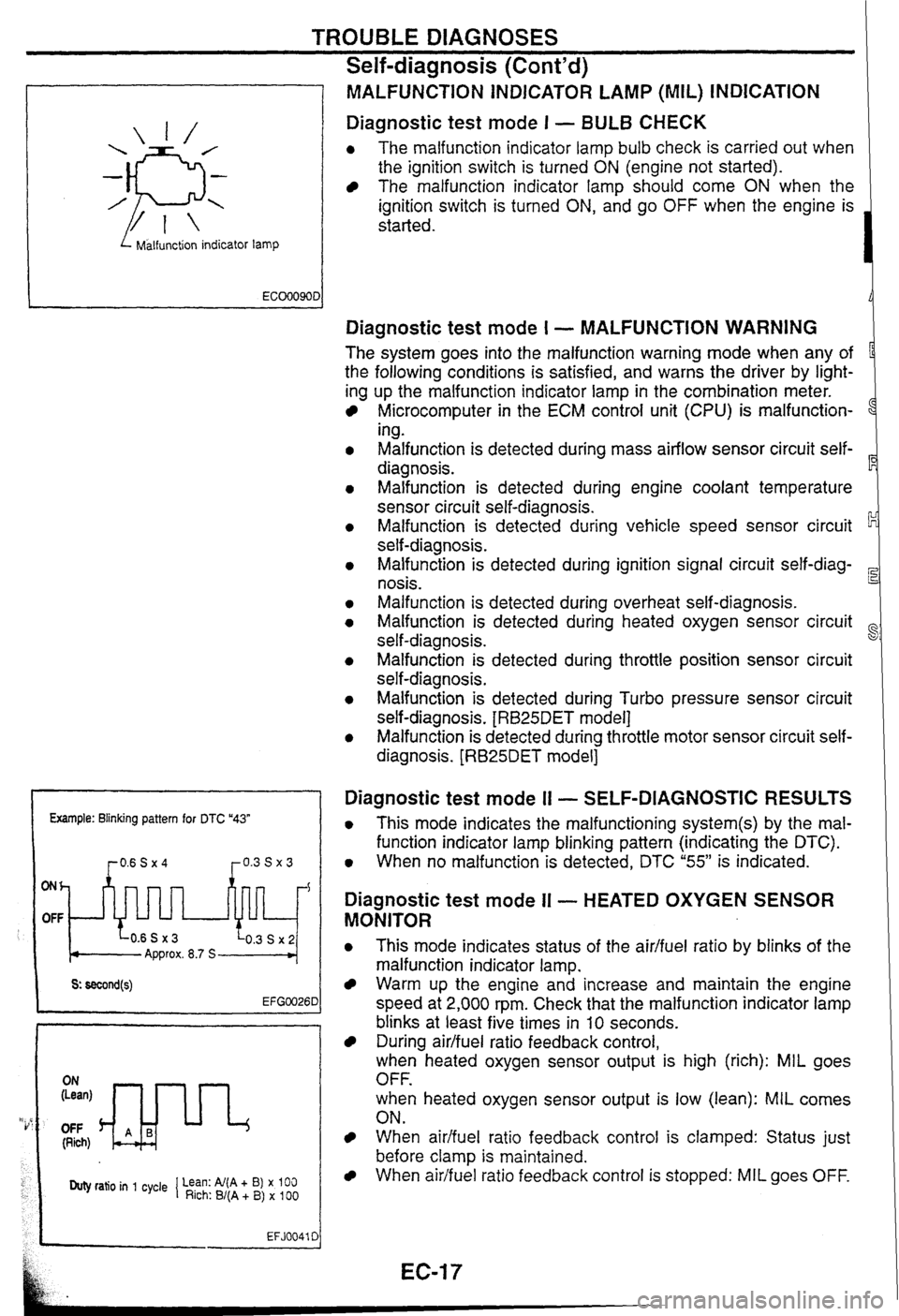
MALFUNCTiON INDICATOR LAMP (MIL) INDICATION
Diagnostic test mode I - BULB CHECK
0 The malfunction indicator lamp bulb check is carried out when
the ignition switch is turned
ON (engine not started).
The malfunction indicator lamp should come ON when the
ignition switch is turned
ON, and go OFF when the engine is
started.
Example: Blinking pattern for DTC "43"
ONh
OFF
Approx. 8.7 S
OFF (Rich)
Duty ratio in 1 cycle 1 Lean: Al(A + B) x 100 Rich: B/(A + B) x 100
EFJ0041 C
Diagnostic test mode I - MALFUNCTION WARNING
The system goes into the malfunction warning mode when any of
the following conditions is satisfied, and warns the driver by light-
ing up the malfunction indicator lamp in the combination meter.
Microcomputer in the ECM control unit (CPU) is malfunction-
1
ing.
Malfunction is detected during mass airflow sensor circuit self-
diagnosis.
Malfunction is detected during engine coolant temperature
sensor circuit self-diagnosis.
Malfunction is detected during vehicle speed sensor circuit
self-diagnosis.
Malfunction is detected during ignition signal circuit
self-diag-
nosis.
Malfunction is detected during overheat self-diagnosis.
Malfunction is detected during heated oxygen sensor circuit
self-diagnosis.
~alfunsion is detected during throttle position sensor circuit
self-diagnosis.
Malfunction is detected during Turbo pressure sensor circuit
self-diagnosis.
[RB25DET model]
Malfunction is detected during throttle motor sensor circuit self-
diagnosis.
[RB25DET model]
Diagnostic test mode I1 - SELF-DIAGNOSTIC RESULTS
0 This mode indicates the malfunctioning system(s) by the mal-
function indicator lamp blinking pattern (indicating the DTC).
0 When no malfunction is detected, DTC "55" is indicated.
Diagnostic test mode II - HEATED OXYGEN SENSOR
MONITOR
0 This mode indicates status of the aidfuel ratio by blinks of the
malfunction indicator lamp.
Warm up the engine and increase and maintain the engine
speed at 2,000 rpm. Check that the malfunction indicator lamp
blinks at least five times in
10 seconds.
During airlfuel ratio feedback control,
when heated oxygen sensor output is high (rich): MIL goes
OFF.
when heated oxygen sensor output is low (lean):
MIL comes
ON.
When aidfuel ratio feedback control is clamped: Status just
before clamp
is maintained.
When airifuel ratio feedback control is stopped: MIL goes OFF.
Page 64 of 230

TROUBLE DIAGNOSES
Control Unit InputlOutput Signal Specifications
(Cont'd)
Terminal
No.' Operation
or measurement condition
Specifications
Total control signal
(multiple communication)
(Except
RB20DE) Refer to
EC section
("ECM.TCM or ECM Input1
Output Signal Reference Value").
I I
I Turn ignition swi?ch ON. I Battery voltage
Power supply (Backup)
Line pressure solenoid - - Turn ignition switch OFF. Battery voltage
r After engine
warm-up, depress accelerator pedal
Line pressure solenoid
(dropping resistor circuit) 5
Approx. OV
w
0.
s
Overrun clutch solenoid After engine
wan-up, release accelerator pedal.
After engine warm-up, release accelerator pedal.
After engine warm-up, depress accelerator pedal
fullv. .- >. .- 5
POWER indicator lamp (4AT)
Dual rnatic
AK waming lamp
(M-AT)
Approx. 1.5 - 3.OV
Approx. 4 - 14V
Approx. OV
When POWER indicator lamp is tumed on (W
mode switch: POWER), or dual matic warn-
ing lamp
is turned on
When
overrun clutch solenoid operates
When overrun clutch solenoid does not operate
Approx.
OV
Battery voltage Approx.
OV
When POWER indicator lamp is tumed off (NT
mode switch:Except POWER), or dual matic A/T Battery voltage
I warning lamp is turned off 1
I When vehicle is locked UD I Approx. 8 - 15V Lock-up solenoid I . .
When vehicle is not locked up I Approx. OV
When shift solenoid A operates
(Driving in 'Dln or
"D,")
When
shift solenoid A does not operate
(Driving in
"D," or "D,")
parenthesis
(
Battery voltage
Approx.
OV
Shift solenoid B
) shows the terminal No. for TCM (RB25DE ).
I
*: Each
When shift solenoid B operates
(Driving in 'Dln or
'D,")
When shift solenoid
B does not operate
(Driving in
"D,"
or
"Dd)
number Battery voltage
Approx. OV
Page 75 of 230

TROUBLE DIAGNOSES
Self-diagnosis
DESCRIPTION
If malfunction should occur in electrical systems, turning ignition switch ON lights M mode switch POWER
indicator lamp
(M-AT Dual matic AfT warning lamp) for 2 seconds, and then flashes the indicator lamp for 8 Gc
seconds. If malfunction does not occur, A/T mode switch POWER indicator lamp (M-AT Dual matic A/T warn-
ing lamp) is turned on for
2 seconds upon turning ignition switch ON. To locate and display the malfunction-
ing part, output the trouble information memory and flash
A/T mode switch POWER indicator lamp (M-AT Dual
matic
A/T warning lamp) by inputting self-diagnostic startup signal.
SELF-DIAGNOSIS PROCEDURE
1. Warm up engine.
2. Repeat ON-OFF cycles of ignition switch for more than once, and turn it OFF at last.
3. Move A/T mode switch to AUTO, and turn overdrive control switch to O/D ON.
4. Turn ignition switch ON with selector lever in "Pn position, and ensure POWER indicator lamp is turned on
for
2 seconds.
5. Turn ignition switch OFF.
6. Move selector lever to "D" position.
7. Turn overdrive control switch O/D OFF.
8. Turn ignition switch ON.
9. Move selector lever to "2" position.
10. Turn overdrive control switch OID ON.
11. Move selector lever to "I" position.
12. Turn overdrive control switch O/D OFF.
13. Depress accelerator pedal fully, and release it.
14. Read flashing status of POWER indicator lamp to complete self-diagnosis procedures.
M-AT
1. Warm up engine.
2. Repeat ON-OFF cycles of ignition switch for more than once, and turn it OFF at last.
3. Turn ignition switch ON with selector lever in "P" position, and ensure dual matic PJT warning lamp is turned
on for
2 seconds.
4. Turn ignition switch OFF.
5. Depress brake pedal, release accelerator pedal, and then move selector lever to "D" position.
6. Turn ignition switch ON.
7. Release brake pedal, and move selector lever to "3" position.
8. While depressing brake pedal with left foot, depress accelerator pedal fully with right foot, and move
selector lever to
"2" position.
9. Read dual matic A/T warning lamp indication to complete self-diagnosis procedures.
Page 76 of 230

TROUBLE DIAGNOSES
Self-diagnosis (Cont'd)
\ I1 // \ 11 // =-I= or =mj= // 11 \ // 11 \
1, = 2.5 sec. t, = 2.0 sec. t, = 1.0 sec.
RB20DE 10 judgement flashes.
Stan signal Malfunctioning unit and circuit I
Except RBPODE 13 judgement flashes.
signal Malfunctioning unit and circuit I
POWER INDICATOR LAMP OR DUAL MATIC A/T
WARNING LAMP INDICATION
If malfunction occurs in electrical system, indicator lamp stays on
longer at corresponding circuit.
Flashing
order
t5 1 Overrun clutch solenoid
1
2
3
4
5
7 1 Lock-up solenoid
Malfunctioning
unit and circuit
Vehicle speed sensor
1
Vehicle speed sensor 2
Throttle position sensor
Shift solenoid
A
Shift solenoid B
I
W fluid temperature sensor, TCM power supply, or throttle posi-
tion sensor power supply
RB20DE
9 1 Engine speed
signal Except
RB20DE
10 1 Line
pressure solenoid I Turbine sensor
I - I Line pressure solenoid
12 1 - I Total control signal
When indicator lamp repeats flashing in 4 Hz, the following malfunctions
may exist: (Insufficient memory backup
powerflCM repiacement1Battery
has been disconnected for prolonged
periodllow battery power)
13
No flashes
HOW TO ERASE SELF-DIAGNOSTIC RESULTS
To facilitate cause investigation of malfunction that is less likely to
reappear, the TCM always stores self-diagnostic results during cus-
tomer operation. This memory cannot be erased even if ignition
switch
is turned ON and OFF repeatedly. To erase the seif-diag-
nostic
results, turn ignition switch
OFF after self-diagnosis has
been performed, or use
"ERASE" function of CONSULT.
- - - - Shift control unit
PNP switch, idle
switch/full switch
Overdrive control switch Stop lamp switch
Page 81 of 230

ANTI-LOCK BRAKE SYSTEM
Fail-safe Function
If any malfunction is detected in the system, the ABS warning lamp
in the instrument panel is turned on with the ABS deactivated and
the vehicle's brake system reverts to normal operation.
System Diagram
ABS control uni: Actuator
Front lefl wheel sensor
Rear wheel Sensor Front
right inlet solenoid valve 1 I -
L ' Data ltnk connector
for CONSULT
Front right outlet solenold valve
Front lett rnlet solenoid vJve
Front left cutlet solenoid valve
r i Rear inlet solenold valve
Contrd
circuit I
Rear outlet solenoid valve
-A Motor (motor relay)
-- Actuator relay
Faii-safe
circuit
TrO~ble
diagnos~s
circuit ABS
warning lamp
Page 84 of 230

ANTI-LOCK BRAKE SYSTEM
ABS control unit connector
Terminal No.
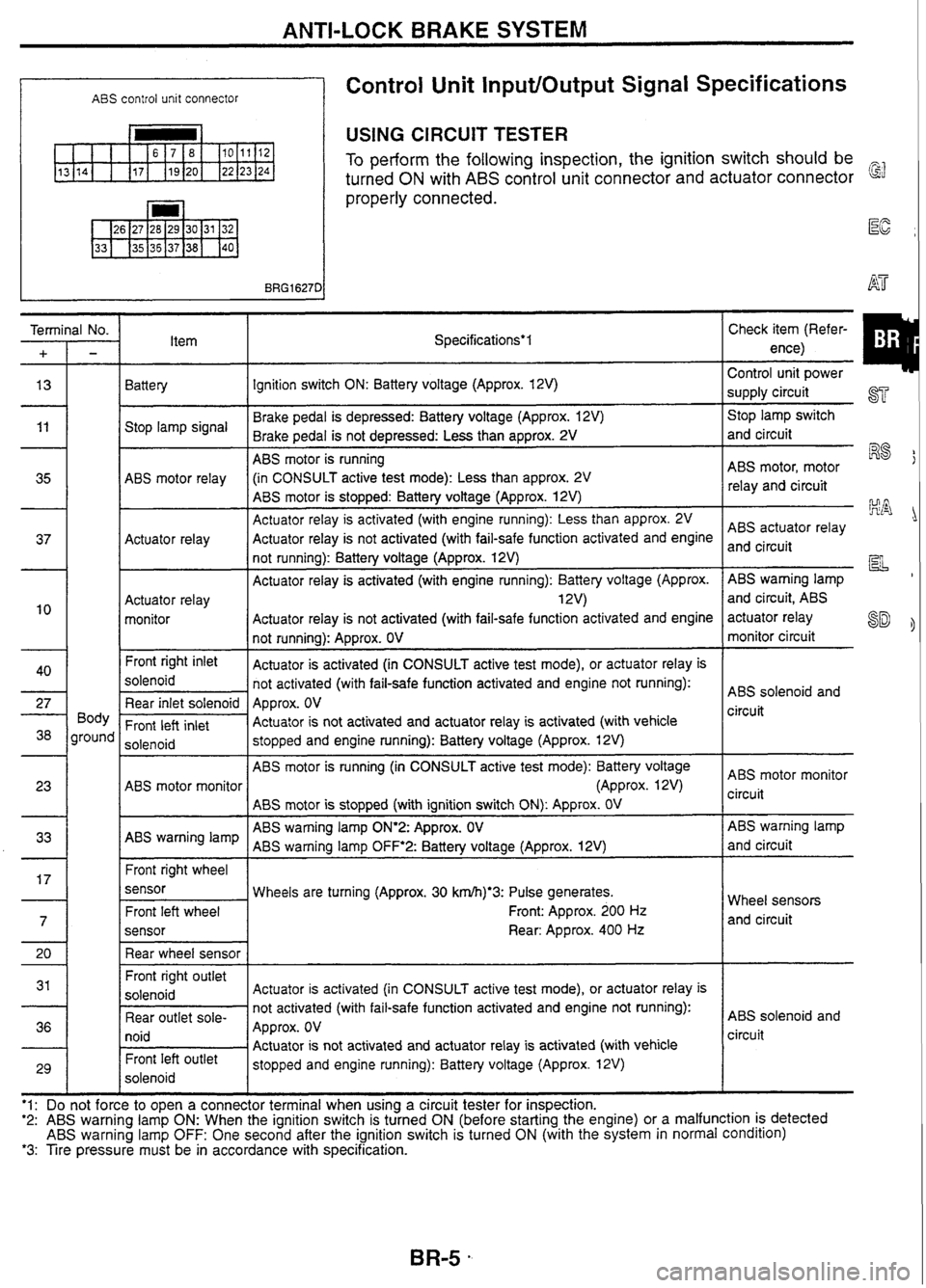
Control Unit InputlOutput Signal Specifications
USING CIRCUIT TESTER
To perform the following inspection, the ignition switch should be
turned
ON with ABS control unit connector and actuator connector
properly connected.
Item Specifications*l
Battery Ignition switch ON: Battery voltage (Approx. 12V)
Brake pedal is depressed: Battery voltage (Approx. 12V)
Stop lamp signal
Brake pedal is not depressed: Less than approx.
2V
ABS motor is running
ABS motor relay (in
CONSULT active test mode): Less than approx.
2V
ABS motor is stopped: Battery voltage (Approx.
12V)
Actuator relay is activated (with engine running): Less than approx. 2V
Actuator relay Actuator
relay is not activated (with fail-safe function activated and engine
not running): Battery voltage (Approx. 12V)
Actuator relay is activated (with engine running): Battery voltage (Approx.
Actuator relay 1 2V)
monitor Actuator
relay is not activated (with fail-safe function activated and engine
not running): Approx. OV
Front
right inlet
Actuator is activated (in CONSULT active test mode), or actuator relay is
solenoid not activated (with fail-safe function activated and engine not running):
Rear inlet solenoid Approx. OV
Front
left inlet Actuator
is not activated and actuator relay is activated (with vehicle
solenoid stopped
and engine running): Battery voltage (Approx. 12V)
ABS motor is running (in CONSULT active test mode): Battery voltage
ABS motor monitor (Approx. 12V)
ABS motor is stopped (with ignition switch
ON): Approx. OV
ABS warning lamp
ON'2:
Approx. OV
ABS warning lamp
ABS warning lamp
OFF'2:
Battery voltage (Approx. 12V)
Front right wheel
sensor Wheels are turning (Approx. 30
krn/h)*3: Pulse generates.
Front: Approx. 200
Hz
sensor
Rear: Approx. 400 Hz
Front right outlet
Actuator is activated (in CONSULT active test mode), or actuator relay is
not activated (with fail-safe function activated and engine not running):
Rear outlet
sole-
Approx. OV
I lUlU / Actuator is not activated and actuator relay is activated (with vehicle Front left Outlet stopped and engine running): Battery voltage (Approx. 12V)
solenoid
'1:e
to
tooen
a connector terminal when
using a circuit tester for inspection. Control
I
unit
power
supply circuit
ST
Stop lamp switch
and circuit
ABS motor, motor
R8
relay and circuit
ABS actuator relay
and circuit
pL
ABS warning lamp
and circuit, ABS
actuator relay
SD monitor circuit
ABS solenoid and
circuit
ABS motor monitor
circuit
ABS warning lamp
and circuit
Wheel sensors and circuit
ABS solenoid and
circuit
'2: ABS warning lamp ON: When the ignition switch is turned ON (before starting the engine) or a malfunction is detected ABS warning lamp OFF: One second after the ignition switch is turned ON (with the system in normal condition) *3: Tire pressure must be in accordance with specification.
Page 85 of 230

ANTI-LOCK BRAKE SYSTEM
Control Unit InputfOutput Signal Specifications
(Cont'd)
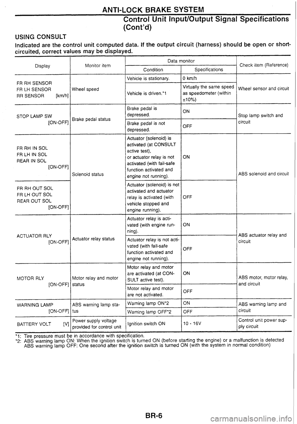
USING CONSULT
Indicated are the control unit computed data. If the output circuit (harness) should be open or short-
circuited, correct values may be displayed.
Check item (Reference)
Data monitor
Display Condition
Monitor
item
Specifications
Vehicle is stationary.
I 0 kdh
FR RH SENSOR
FR LH SENSOR
RR SENSOR
[kdh]
Virtually the same speed
as speedometer (within
+I 0%)
Wheel sensor and circuit
Wheel speed
Vehicle is
drivem'l
Brake pedal is
depressed. Stop lamp switch and
circuit
STOP
LAMP SW
[ON-OFF] Brake pedal status
Brake pedal is not
depressed. OFF
-- --
Actuator (solenoid)
is
activated (at CONSULT
active test),
or
actuator relay is not
activated (with fail-safe
function activated and
engine not running).
FR
RH IN SOL
FR
LH IN SOL
REAR IN SOL
[ON-OFF]
ABS solenoid and circuit
Solenoid status
FR RH OUT SOL
FR
LH OUT SOL
REAR OUT SOL
[ON-OFF]
-- -- - -- -
Actuator (solenoid) is not
activated and actuator
relay is activated (with
vehicle stopped and
engine running).
Actuator relay is acti-
vated (with engine run-
ning).
Actuator relay is not acti-
vated (with fail-safe
function activated and
engine not running).
ABS actuator relay and
circuit
OFF
ON
OFF
ACTUATOR
RLY
[ON-OFF] Actuator
relay status
Motor relay and motor
are activated (at CON-
SULT active test). ABS
motor, motor relay,
and circuit
MOTOR
RLY
[ON-OFF] Motor
relay and motor
status Motor relay and motor
are not activated. OFF
ABS warning lamp and
circuit
- -
Waming lamp ON'2 1 ON
WARNING LAMP
[ON-OFF] ABS
warning lamp sta-
tus
Power supply voltage
provided for control unit -- -
Warning lamp OFF'2 1 OFF
Control unit power sup-
ply circuit - -
BAlTERY VOLT [V] Ignition switch
ON
'1: Tire pressure must be in accordance with specification. "2: ABS warning lamp ON: When the ignition switch is turned ON (before starting the engine) or a malfunction is detected ABS warning lamp OFF: One second after the ignition switch is turned ON (with the system in normal condition)
Page 86 of 230

ANTI-LOCK BRAKE SYSTEM
Precautions for Trouble Diagnosis
After performing trouble diagnosis, be sure to erase trouble stored in memory. Refer to "CONSULT' (next
page) or "SELF-DIAGNOSIS"
(BR-15).
As for the concerns that are difficult to duplicate, move harnesses or harness connectors by hand to check
if there is any poor mating of connector halves or faulty connection.
Do not force to open a connector terminal when using a circuit tester for inspection.
Read GI section thoroughly in advance and make sure of all the general precautions.
Basic Inspection
BASIC INSPECTION 1 - Brake fluid level and leakage AT
1. Check brake fluid level in reservoir tank. Replenish brake fluid if necessary.
2. Check for leakage at or around brake piping and ABS actuator. If leakage or seepage is noted, proceed
as follows:
If ABS actuator connectors are loose, tighten to specified torque. Recheck to ensure that leakage is no
longer present.
If flare nut threads at piping connectors or actuator threads are damaged, replace faulty parts with new 87
ones. Recheck to ensure that leakage is no longer present.
If brake fluid leaks through areas other than actuator connectors, wipe off using a clean cloth. Recheck
for leakage or seepage. If necessary, replace faulty parts with new ones.
R8
If brake fluid leaks at or seeps through ABS actuator, wipe off using a clean cloth. Recheck for leakage
or seepage. If necessary, replace
ABS actuator with new one.
CAUTION: HA
ABS actuator cannot be disassembled. Do not attempt to disassemble it.
BASIC INSPECTION 2 - Loose power line terminal
Check battery terminals (positive and negative) and battery mounting (ground) for looseness.
BASIC INSPECTION 3 - ABS warning lamp
1. Turn ignition switch "ON" to ensure that ABS warning lamp lights up for approximately 1 second. If ABS
warning lamp does not light, check ABS warning lamp circuit.
2. After driving vehicle at approx. 30 km/h for approx. 1 minute, check to ensure that ABS warning lamp
remains off. If ABS warning lamp lights, perform self-diagnosis procedures.
3. After performing self-diagnosis procedures, be sure to erase trouble stored in memory.
Page 87 of 230

ANTI-LOCK BRAKE SYSTEM
CONSULT
CONTROL UNIT PART NUMBER
The part number that is shown on the control unit label and CON-
SULT 47850 AAOOO
- SELF-DIAGNOSIS PROCEDURE
Coliect information on the concern from the customer, and then
perform basic inspections.
Turn ignition switch
OFF and connect CONSULT connector to
data link connector for CONSULT on the vehicle.
Start engine and drive vehicle at approx.
30 km/b for approx.
1 minute.
Stop vehicle and touch "START",
"ABS" and "SELF-DIAG
RESULTS" sequentially on the CONSULT screen with engine
running.
If "START" is touched immediately after engine is started
or ignition switch is turned on,
"ABS" may not be dis-
played on "SELECT
SYSTEM" screen. To display "ABS",
repeat the self-diagnosis procedure from the beginning.
Self-diagnosis results are displayed on the screen. (Touch
"PRINT" to print out the self-diagnosis results, if necessary.)
If
"NO FAIL" is displayed, inspect ABS warning lamp. Refer to
the previous page.
Perform appropriate inspection from the self-diagnostic results
mode and repair or replace faulty parts.
Start engine and drive vehicle at approx. 30
km/b for approx.
1 minute.
Recheck to ensure that there is no other malfunction.
Turn ignition switch OFF to prepare for erasing the trouble
stored in memory.
Start engine and touch "START",
"ABS", "SELF-DIAG
RESULTS" and "ERASE" sequentially on the CONSULT
screen to erase the trouble stored in memory.
If the trouble stored in memory is not erased, repeat step
6.
10. Drive vehicle at approx. 30 km/h for approx. 1 minute and then
confirm that ABS warning lamp is
off.