fuel NISSAN GT-R 2013 R35 User Guide
[x] Cancel search | Manufacturer: NISSAN, Model Year: 2013, Model line: GT-R, Model: NISSAN GT-R 2013 R35Pages: 346, PDF Size: 4.19 MB
Page 97 of 346
Cruise control system warning .................................... 2-39
Low fuel warning ............................................................. 2-39
Door/trunk open warning .............................................. 2-40
Low washer fluid warning ............................................. 2-40
No key warning ................................................................ 2-40
Operation displays ................................................................ 2-41 Engine start operation indicator .................................. 2-41
Shift “P” warning ............................................................. 2-42
“PUSH” warning .............................................................. 2-42
Steering lock release malfunction indicator ............. 2-42
Intelligent Key insertion indicator ................................ 2-43
Intelligent Key removal indicator .................................. 2-43
Intelligent Key battery discharge indicator ................ 2-43
Security systems ................................................................... 2-44
Vehicle security system ................................................. 2-44
NISSAN Vehicle Immobilizer System ......................... 2-45
Windshield wiper and washer switch .............................. 2-46 Using the wipers ............................................................. 2-47
Using the washer ............................................................ 2-48
Rear window defroster switch ........................................... 2-48
Headlight and turn signal switch ...................................... 2-49
Xenon headlights ............................................................. 2-49
Headlight switch .............................................................. 2-49
Hazard warning flasher switch .......................................... 2-52
Horn ........................................................................\
.................. 2-53 Heated seats (if so equipped) .......................................... 2-53
Turning on the heaters ................................................. 2-53
Turning off the heaters ................................................. 2-53
Power outlets ........................................................................\
2-54
Storage ........................................................................\
........... 2-55 Cup holders .................................................................... 2-55
Sunglasses holder ........................................................ 2-56
Door pocket .................................................................... 2-57
Glove box ........................................................................\
2-57Console box ................................................................... 2-58
Coat hooks ..................................................................... 2-58
Windows ........................................................................\
........ 2-59 Power windows ............................................................. 2-59
Interior lights ........................................................................\
.. 2-61
Map lights ....................................................................... 2-61
Interior light control switch ......................................... 2-62
Vanity mirror lights ................................................................ 2-63
HomeLink
®Universal Transceiver .................................... 2-63
Programming HomeLink®............................................ 2-64
Programming HomeLink®for
Canadian customers .................................................... 2-65
Operating the HomeLink
®universal transceiver ... 2-65
Programming trouble-diagnosis ................................ 2-65
Clearing the programmed information ..................... 2-66
Reprogramming a single HomeLink
®button ......... 2-66
If your vehicle is stolen ................................................ 2-66
Page 100 of 346
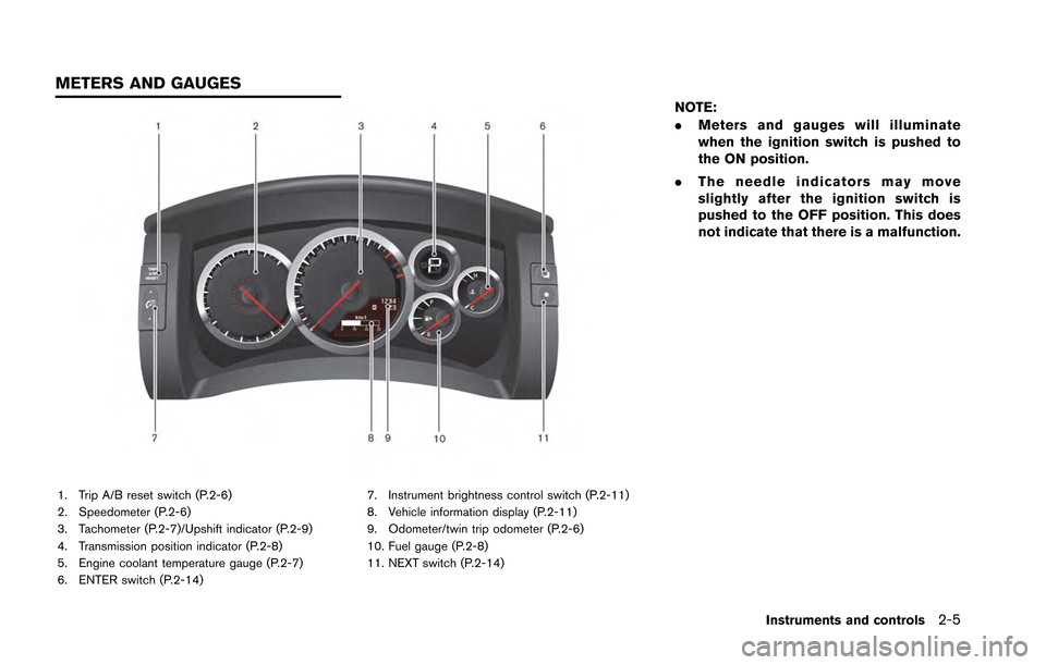
1. Trip A/B reset switch (P.2-6)
2. Speedometer (P.2-6)
3. Tachometer (P.2-7)/Upshift indicator (P.2-9)
4. Transmission position indicator (P.2-8)
5. Engine coolant temperature gauge (P.2-7)
6. ENTER switch (P.2-14)7. Instrument brightness control switch (P.2-11)
8. Vehicle information display (P.2-11)
9. Odometer/twin trip odometer (P.2-6)
10. Fuel gauge (P.2-8)
11. NEXT switch (P.2-14)
NOTE:
.
Meters and gauges will illuminate
when the ignition switch is pushed to
the ON position.
. The needle indicators may move
slightly after the ignition switch is
pushed to the OFF position. This does
not indicate that there is a malfunction.
Instruments and controls2-5
METERS AND GAUGES
Page 103 of 346
2-8Instruments and controls
FUEL GAUGE
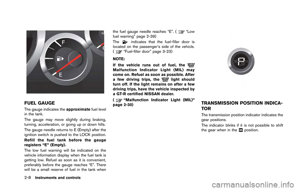
The gauge indicates theapproximatefuel level
in the tank.
The gauge may move slightly during braking,
turning, acceleration, or going up or down hills.
The gauge needle returns to E (Empty) after the
ignition switch is pushed to the LOCK position.
Refill the fuel tank before the gauge
registers “E” (Empty) .
The low fuel warning will be indicated on the
vehicle information display when the fuel tank is
getting low. Refuel as soon as it is convenient,
preferably before the gauge reaches “E”. There
will be a small reserve of fuel in the tank when the fuel gauge needle reaches “E”. (
“Low
fuel warning” page 2-39)
The
indicates that the fuel-filler door is
located on the passenger’s side of the vehicle.
(
“Fuel-filler door” page 3-23)
NOTE:
If the vehicle runs out of fuel, the
Malfunction Indicator Light (MIL) may
come on. Refuel as soon as possible. After
a few driving trips, the
light should
turn off. If the light remains on after a few
driving trips, have the vehicle inspected by
a GT-R certified NISSAN dealer.
(
“Malfunction Indicator Light (MIL)”
page 2-30)TRANSMISSION POSITION INDICA-
TOR
The transmission position indicator indicates the
gear positions.
The indicator blinks if it is not possible to shift
the gear when in the
&Mposition.
Page 109 of 346
2-14Instruments and controls
after the system check is finished.
Release the button and push it again
to operate the shift lever.
. During winter or at other times when
the temperature is extremely low,
changes in the hydraulic response
characteristics may increase the
amount of time that is required for the
system check. During the system check,
a thudding operating noise may occur
or the engine speed may decrease,
however this does not indicate that
there is a malfunction.
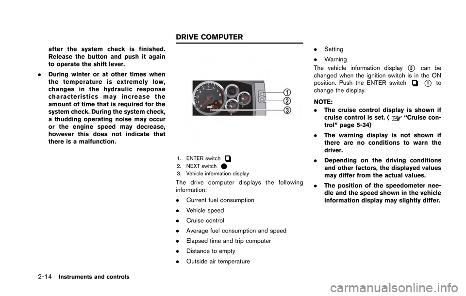
1. ENTER switch2. NEXT switch3. Vehicle information display
The drive computer displays the following
information:
.Current fuel consumption
. Vehicle speed
. Cruise control
. Average fuel consumption and speed
. Elapsed time and trip computer
. Distance to empty
. Outside air temperature .
Setting
. Warning
The vehicle information display
*3can be
changed when the ignition switch is in the ON
position. Push the ENTER switch
*1to
change the display.
NOTE:
. The cruise control display is shown if
cruise control is set. (
“Cruise con-
trol” page 5-34)
. The warning display is not shown if
there are no conditions to warn the
driver.
. Depending on the driving conditions
and other factors, the displayed values
may differ from the actual values.
. The position of the speedometer nee-
dle and the speed shown in the vehicle
information display may slightly differ.
DRIVE COMPUTER
Page 110 of 346
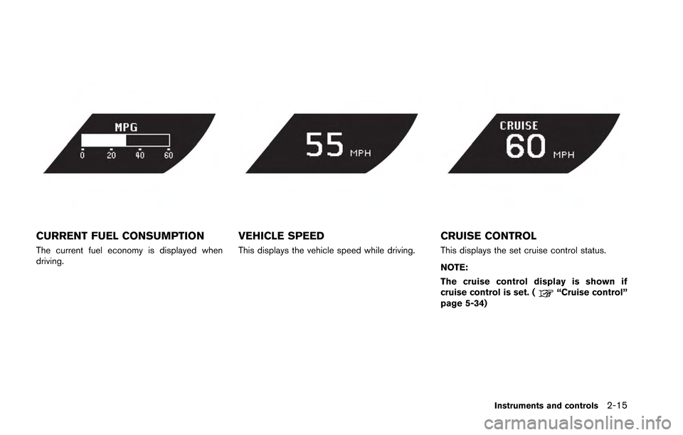
CURRENT FUEL CONSUMPTION
The current fuel economy is displayed when
driving.
VEHICLE SPEED
This displays the vehicle speed while driving.
CRUISE CONTROL
This displays the set cruise control status.
NOTE:
The cruise control display is shown if
cruise control is set. (
“Cruise control”
page 5-34)
Instruments and controls2-15
Page 111 of 346
2-16Instruments and controls
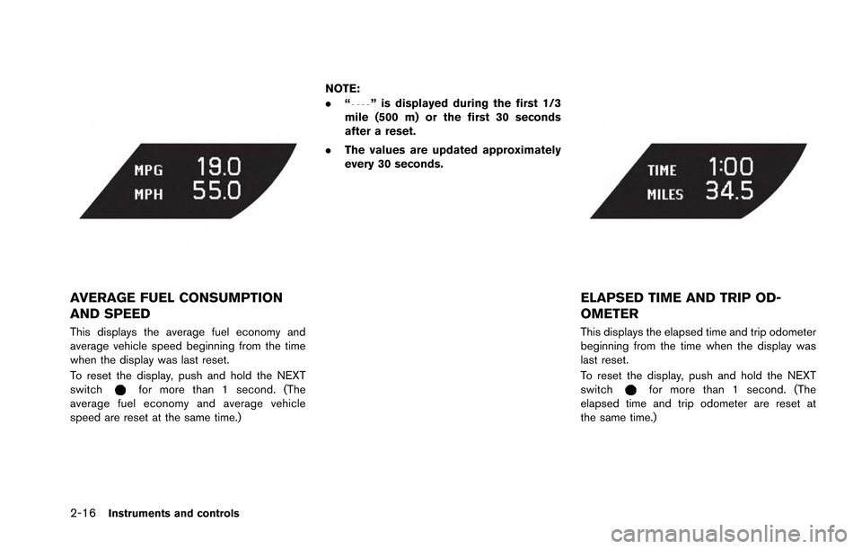
AVERAGE FUEL CONSUMPTION
AND SPEED
This displays the average fuel economy and
average vehicle speed beginning from the time
when the display was last reset.
To reset the display, push and hold the NEXT
switch
for more than 1 second. (The
average fuel economy and average vehicle
speed are reset at the same time.) NOTE:
.
“
” is displayed during the first 1/3
mile (500 m) or the first 30 seconds
after a reset.
. The values are updated approximately
every 30 seconds.
ELAPSED TIME AND TRIP OD-
OMETER
This displays the elapsed time and trip odometer
beginning from the time when the display was
last reset.
To reset the display, push and hold the NEXT
switch
for more than 1 second. (The
elapsed time and trip odometer are reset at
the same time.)
Page 112 of 346
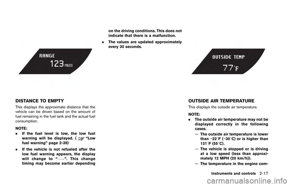
DISTANCE TO EMPTY
This displays the approximate distance that the
vehicle can be driven based on the amount of
fuel remaining in the fuel tank and the actual fuel
consumption.
NOTE:
.If the fuel level is low, the low fuel
warning will be displayed. (
“Low
fuel warning” page 2-39)
. If the vehicle is not refueled after the
low fuel warning appears, the display
will change to “
”. This change
timing may become earlier depending on the driving conditions. This does not
indicate that there is a malfunction.
. The values are updated approximately
every 30 seconds.
OUTSIDE AIR TEMPERATURE
This displays the outside air temperature.
NOTE:
.The outside air temperature may not be
displayed correctly in the following
cases.
—The outside air temperature is lower
than −228F( −308C) or is higher than
1318F (558C) .
— The vehicle is stopped or is driving
at a low speed (less than approxi-
mately 12 MPH (20 km/h)) .
— The temperature in the engine com-
Instruments and controls2-17
Page 125 of 346
2-30Instruments and controls
NOTICE
While the warning light is illuminated,
the engine output is controlled so that
it does not increase.
Vehicle Dynamic Control (VDC)
warning light
The light will blink when the VDC system or the
traction control system is operating, thus alerting
the driver that the vehicle is nearing its traction
limits. The road surface may be slippery.
If the VDC warning light illuminates when the
VDC system is turned on, this light alerts the
driver to the fact that the VDC system’s fail-safe
mode is operating, for example the VDC or hill
start assist system may not be functioning
properly. Have the system checked by a GT-R
certified NISSAN dealer. If a malfunction occurs
in the system, the VDC system function will be
canceled but the vehicle is still driveable.
(
“Vehicle Dynamic Control (VDC) system”
page 5-49)
INDICATOR LIGHTS
Cruise main switch indicator
light
The light comes on when the cruise control is
pushed. The light turns off when the main switch
is pushed again. While the cruise control system
main switch indicator light is on, the cruise
control system is operational.
Cruise set switch indicator
light
The light comes on while the vehicle speed is
controlled by the cruise control system. If the
light blinks while the engine is running, it may
indicate the cruise control system is not
functioning properly. Have the system checked
by a GT-R certified NISSAN dealer.
Exterior light indicator
This indicator illuminates when the headlight
switch is turned to the AUTO,orposition and the front parking lights, instrument
panel lights, rear combination lights, license
plate lights or headlights are on. The indicator
turns off when these lights are turned off.
Front passenger air bag status
light
The front passenger air bag status light ()
will be lit and the passenger front air bag will be
OFF depending on how the front passenger
seat is being used. (
“NISSAN Advanced
Air Bag System (front seats)” page 1-37)
High beam indicator light
This light comes on when the headlight high
beam is on and goes out when the low beam is
selected.
Malfunction Indicator Light
(MIL)
If the malfunction indicator light comes on
steady or blinks while the engine is running, it
may indicate a potential emission control mal-
function.
The malfunction indicator light may also come on
steady if the fuel-filler cap is loose or missing, or
if the vehicle runs out of fuel. Check to make
sure the fuel-filler cap is installed and closed
tightly, and that the vehicle has at least 3 US
gallons (12 liters) of fuel in the fuel tank.
After a few driving trips, the
light should
turn off if no other potential emission control
system malfunction exists.
If this indicator light remains on for 20 seconds
Page 126 of 346
and then blinks for 10 seconds when the engine
is not running, it indicates that the vehicle is not
ready for an emission control system inspection/
maintenance test. (
“Readiness for Inspec-
tion/Maintenance (I/M) test (US only)” page 9-
20)
Operation:
The malfunction indicator light will come on in
one of two ways:
. Malfunction indicator light on steady — An
emission control system malfunction has
been detected. Check the fuel-filler cap. If
the fuel-filler cap is loose or missing, tighten
or install the cap and continue to drive the
vehicle. The
light should turn off after a
few driving trips. If thelight does not
turn off after a few driving trips, have the
vehicle inspected by a GT-R certified
NISSAN dealer. You do not need to have
your vehicle towed to the dealer.
. Malfunction indicator light blinking — An
engine misfire has been detected which may
damage the emission control system.
To reduce or avoid emission control system
damage:
a. Do not drive at speeds above 45 MPH
(72 km/h). b. Avoid hard acceleration or deceleration.
c. Avoid steep uphill grades.
d. If possible, reduce the amount of cargo
being hauled or towed.
The malfunction indicator light may stop
blinking and remain on.
Have the vehicle inspected by a GT-R
certified NISSAN dealer. You do not need
to have your vehicle towed to the dealer.
NOTICE
Continued vehicle operation without
having the emission control system
checked and repaired as necessary
could lead to poor driveability, reduced
fuel economy, and possible damage to
the emission control system.
Turn signal/hazard indicator
lights
The light flashes when the turn signal switch
lever or hazard switch is turned on.
Vehicle Dynamic Control (VDC)
off indicator light
The light comes on when the Vehicle Dynamic
Control (VDC) set up switch is pushed to OFF for more than 1 second. (
“VDC, transmis-
sion and suspension setup switches” page 5-
24)
This indicates that the vehicle dynamic control
system and traction control system are not
operating. (
“Vehicle Dynamic Control
(VDC) system” page 5-49)
AUDIBLE REMINDERS
Key reminder chime
A chime will sound if the driver side door is
opened while the ignition switch is pushed to
the ACC position or pushed to the OFF or
LOCK position with the Intelligent Key left in the
Intelligent Key port. Make sure the ignition
switch is pushed to the OFF position, and take
the Intelligent Key with you when leaving the
vehicle.
Light reminder chime
A chime will sound when the driver side door is
opened with the light switch in theorposition and the ignition switch in the ACC, OFF
or LOCK position.
Turn the light switch off when you leave the
vehicle.
Instruments and controls2-31
Page 128 of 346
If there are multiple warnings, the warning lights
remain lit or continue to blink and the warnings
displayed in the vehicle information display are
switched at regular intervals. The warnings
displayed in the vehicle information display can
be switched voluntarily by pushing the ENTER
switch
.
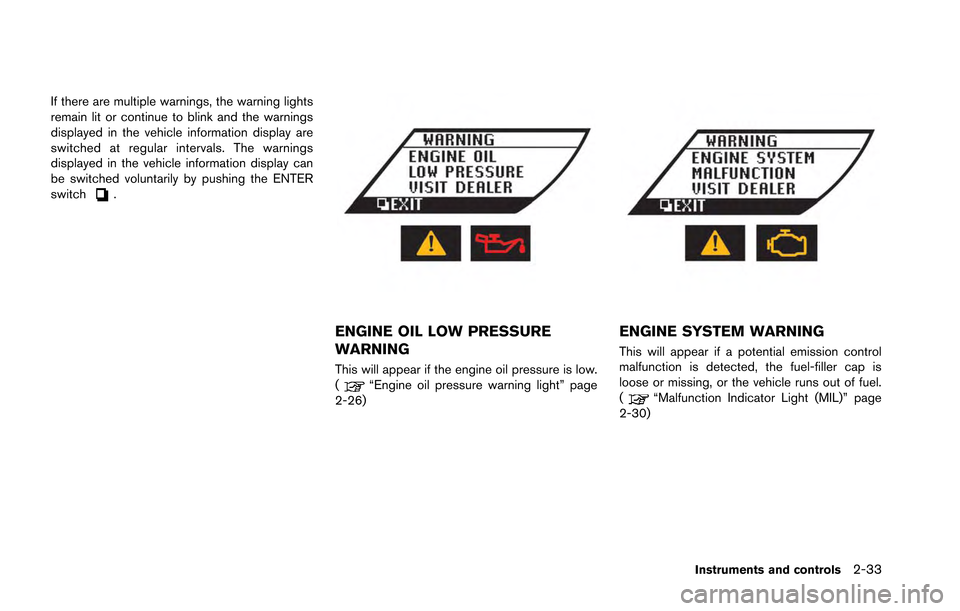
ENGINE OIL LOW PRESSURE
WARNING
This will appear if the engine oil pressure is low.
(“Engine oil pressure warning light” page
2-26)
ENGINE SYSTEM WARNING
This will appear if a potential emission control
malfunction is detected, the fuel-filler cap is
loose or missing, or the vehicle runs out of fuel.
(
“Malfunction Indicator Light (MIL)” page
2-30)
Instruments and controls2-33