NISSAN LATIO 2007 Service Repair Manual
Manufacturer: NISSAN, Model Year: 2007, Model line: LATIO, Model: NISSAN LATIO 2007Pages: 2896, PDF Size: 64.73 MB
Page 2881 of 2896
REAR WIPER AND WASHER SYSTEM
WW-33
C
D
E
F
G
H
I
J
L
MA
B
WW
Revision: June 20062007 Versa
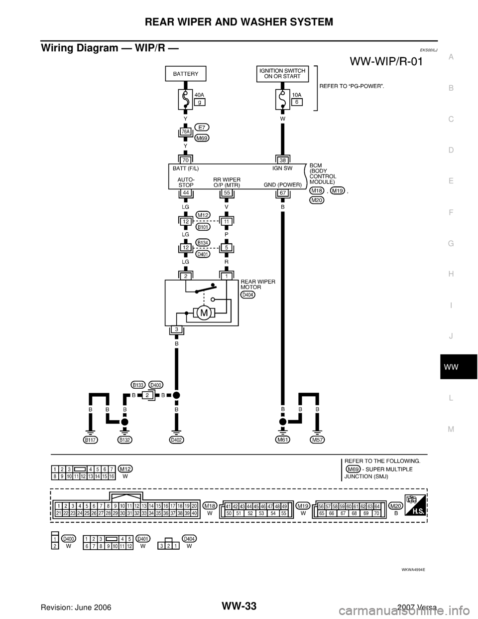
Wiring Diagram — WIP/R —EKS00ILJ
WKWA4994E
Page 2882 of 2896
WW-34
REAR WIPER AND WASHER SYSTEM
Revision: June 20062007 Versa
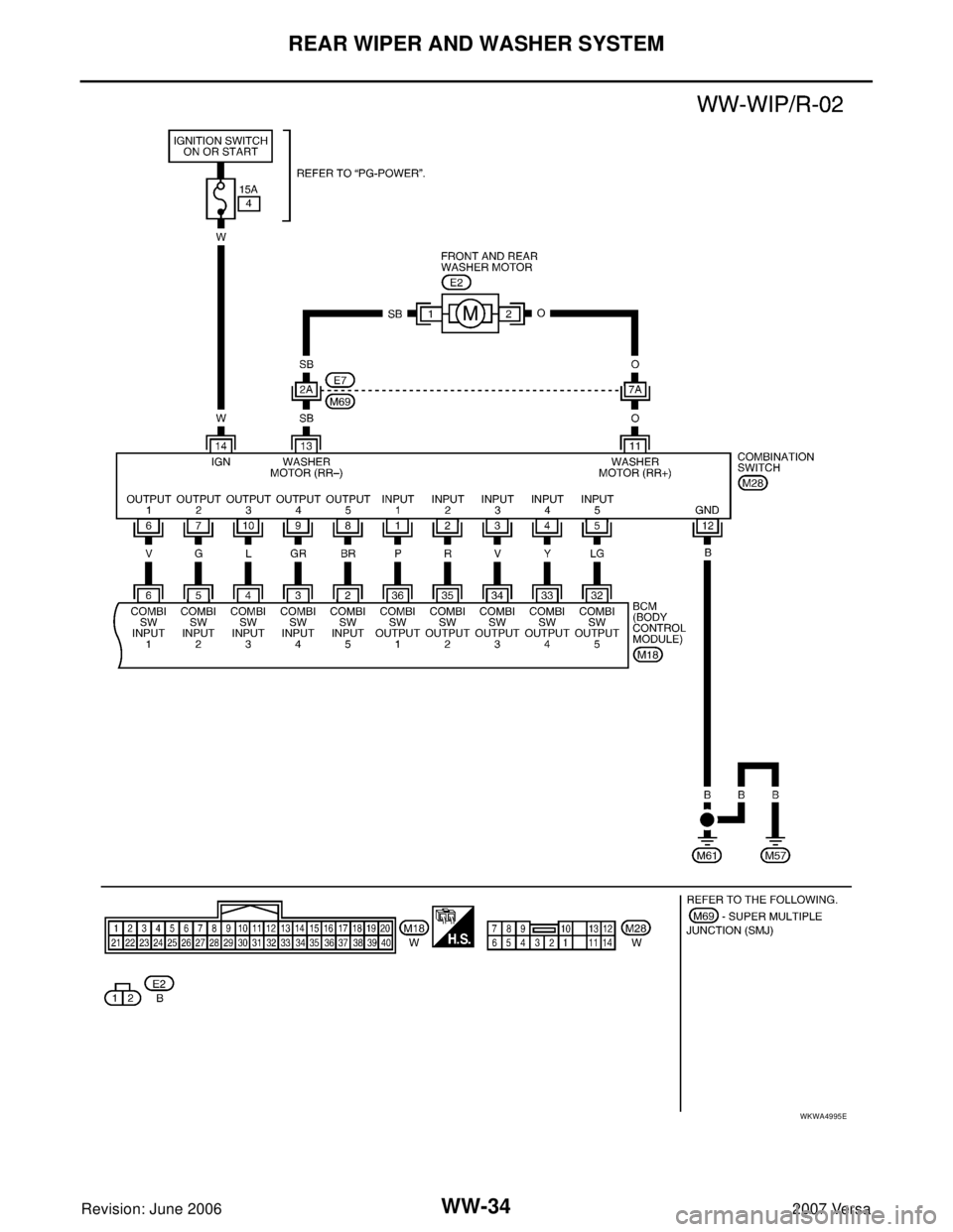
WKWA4995E
Page 2883 of 2896
REAR WIPER AND WASHER SYSTEM
WW-35
C
D
E
F
G
H
I
J
L
MA
B
WW
Revision: June 20062007 Versa
Terminals and Reference Values for BCMEKS00ILK
Refer to BCS-12, "Terminals and Reference Values for BCM" .
How to Proceed With Trouble DiagnosisEKS00ILL
1. Confirm the symptoms and customer complaint.
2. Understand operation description and function description. Refer to WW-30, "
System Description" .
3. Perform the Preliminary Check. Refer to WW-35, "
Preliminary Check" .
4. Check symptom and repair or replace the cause of malfunction.
5. Does the rear wiper operate normally? If YES: GO TO 6. If NO: GO TO 4.
6. Inspection End.
Preliminary CheckEKS00ILM
CHECK POWER SUPPLY AND GROUND CIRCUIT FOR BCM
Refer to BCS-16, "BCM Power Supply and Ground Circuit Check" .
CONSULT-II Function (BCM)EKS00ILN
Refer to WW-12, "CONSULT-II Functions (BCM)" .
Rear Wiper Does Not OperateEKS00ILO
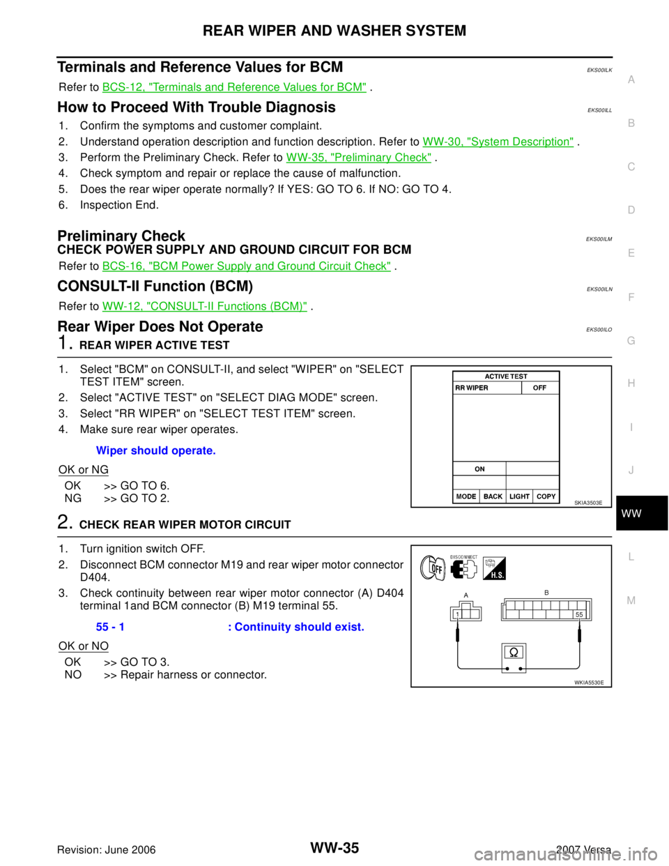
1. REAR WIPER ACTIVE TEST
1. Select "BCM" on CONSULT-II, and select "WIPER" on "SELECT
TEST ITEM" screen.
2. Select "ACTIVE TEST" on "SELECT DIAG MODE" screen.
3. Select "RR WIPER" on "SELECT TEST ITEM" screen.
4. Make sure rear wiper operates.
OK or NG
OK >> GO TO 6.
NG >> GO TO 2.
2. CHECK REAR WIPER MOTOR CIRCUIT
1. Turn ignition switch OFF.
2. Disconnect BCM connector M19 and rear wiper motor connector
D404.
3. Check continuity between rear wiper motor connector (A) D404
terminal 1and BCM connector (B) M19 terminal 55.
OK or NO
OK >> GO TO 3.
NO >> Repair harness or connector.Wiper should operate.
SKIA3503E
55 - 1 : Continuity should exist.
WKIA5530E
Page 2884 of 2896
WW-36
REAR WIPER AND WASHER SYSTEM
Revision: June 20062007 Versa
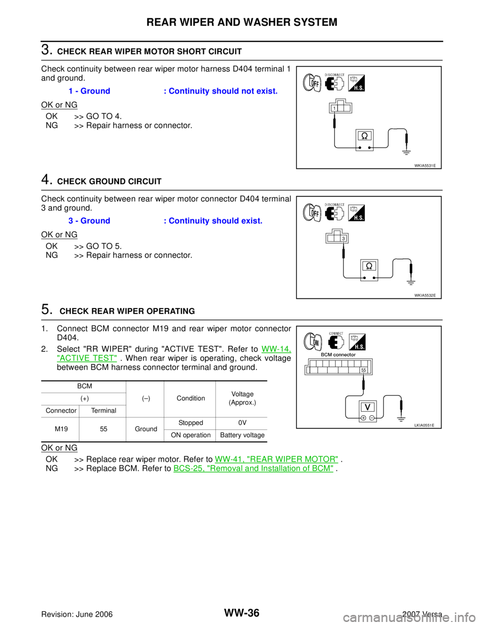
3. CHECK REAR WIPER MOTOR SHORT CIRCUIT
Check continuity between rear wiper motor harness D404 terminal 1
and ground.
OK or NG
OK >> GO TO 4.
NG >> Repair harness or connector.
4. CHECK GROUND CIRCUIT
Check continuity between rear wiper motor connector D404 terminal
3 and ground.
OK or NG
OK >> GO TO 5.
NG >> Repair harness or connector.
5. CHECK REAR WIPER OPERATING
1. Connect BCM connector M19 and rear wiper motor connector
D404.
2. Select "RR WIPER" during "ACTIVE TEST". Refer to WW-14,
"ACTIVE TEST" . When rear wiper is operating, check voltage
between BCM harness connector terminal and ground.
OK or NG
OK >> Replace rear wiper motor. Refer to WW-41, "REAR WIPER MOTOR" .
NG >> Replace BCM. Refer to BCS-25, "
Removal and Installation of BCM" . 1 - Ground : Continuity should not exist.
WKIA5531E
3 - Ground : Continuity should exist.
WKIA5532E
BCM
(–) ConditionVoltage
(Approx.) (+)
Connector Terminal
M19 55 GroundStopped 0V
ON operation Battery voltage
LKIA0551E
Page 2885 of 2896
REAR WIPER AND WASHER SYSTEM
WW-37
C
D
E
F
G
H
I
J
L
MA
B
WW
Revision: June 20062007 Versa
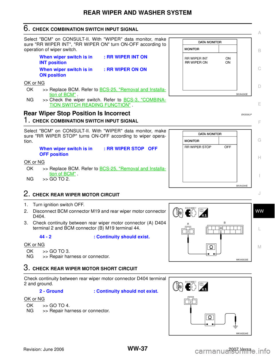
6. CHECK COMBINATION SWITCH INPUT SIGNAL
Select "BCM" on CONSULT-II. With "WIPER" data monitor, make
sure "RR WIPER INT", "RR WIPER ON" turn ON-OFF according to
operation of wiper switch.
OK or NG
OK >> Replace BCM. Refer to BCS-25, "Removal and Installa-
tion of BCM" .
NG >> Check the wiper switch. Refer to BCS-3, "
COMBINA-
TION SWITCH READING FUNCTION" .
Rear Wiper Stop Position Is IncorrectEKS00ILP
1. CHECK COMBINATION SWITCH INPUT SIGNAL
Select "BCM" on CONSULT-II. With "WIPER" data monitor, make
sure "RR WIPER STOP" turns ON-OFF according to wiper opera-
tion.
OK or NG
OK >> Replace BCM. Refer to BCS-25, "Removal and Installa-
tion of BCM" .
NG >> GO TO 2.
2. CHECK REAR WIPER MOTOR CIRCUIT
1. Turn ignition switch OFF.
2. Disconnect BCM connector M19 and rear wiper motor connector
D404.
3. Check continuity between rear wiper motor connector (A) D404
terminal 2 and BCM connector (B) M19 terminal 44.
OK or NG
OK >> GO TO 3.
NG >> Repair harness or connector.
3. CHECK REAR WIPER MOTOR SHORT CIRCUIT
Check continuity between rear wiper motor connector D404 terminal
2 and ground.
OK or NG
OK >> GO TO 4.
NG >> Repair harness or connector. When wiper switch is in
INT position: RR WIPER INT ON
When wiper switch is in
ON position: RR WIPER ON ON
SKIA4243E
When wiper switch is in
OFF position: RR WIPER STOP OFF
SKIA4244E
44 - 2 : Continuity should exist.
WKIA5533E
2 - Ground : Continuity should not exist.
WKIA5534E
Page 2886 of 2896
WW-38
REAR WIPER AND WASHER SYSTEM
Revision: June 20062007 Versa
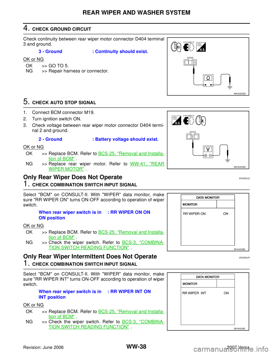
4. CHECK GROUND CIRCUIT
Check continuity between rear wiper motor connector D404 terminal
3 and ground.
OK or NG
OK >> GO TO 5.
NG >> Repair harness or connector.
5. CHECK AUTO STOP SIGNAL
1. Connect BCM connector M19.
2. Turn ignition switch ON.
3. Check voltage between rear wiper motor connector D404 termi-
nal 2 and ground.
OK or NG
OK >> Replace BCM. Refer to BCS-25, "Removal and Installa-
tion of BCM" .
NG >> Replace rear wiper motor. Refer to WW-41, "
REAR
WIPER MOTOR" .
Only Rear Wiper Does Not OperateEKS00ILQ
1. CHECK COMBINATION SWITCH INPUT SIGNAL
Select "BCM" on CONSULT-II. With "WIPER" data monitor, make
sure "RR WIPER ON" turns ON-OFF according to operation of wiper
switch.
OK or NG
OK >> Replace BCM. Refer to BCS-25, "Removal and Installa-
tion of BCM" .
NG >> Check the wiper switch. Refer to BCS-3, "
COMBINA-
TION SWITCH READING FUNCTION" .
Only Rear Wiper Intermittent Does Not OperateEKS00ILR
1. CHECK COMBINATION SWITCH INPUT SIGNAL
Select "BCM" on CONSULT-II. With "WIPER" data monitor, make
sure "RR WIPER INT" turns ON-OFF according to operation of wiper
switch.
OK or NG
OK >> Replace BCM. Refer to BCS-25, "Removal and Installa-
tion of BCM" .
NG >> Check the wiper switch. Refer to BCS-3, "
COMBINA-
TION SWITCH READING FUNCTION" . 3 - Ground : Continuity should exist.
WKIA5535E
2 - Ground : Battery voltage should exist.
WKIA5536E
When rear wiper switch is in
ON position: RR WIPER ON ON
SKIA4248E
When rear wiper switch is in
INT position: RR WIPER INT ON
SKIA4249E
Page 2887 of 2896
REAR WIPER AND WASHER SYSTEM
WW-39
C
D
E
F
G
H
I
J
L
MA
B
WW
Revision: June 20062007 Versa
Wiper Does Not Wipe When Rear Washer OperatesEKS00ILS
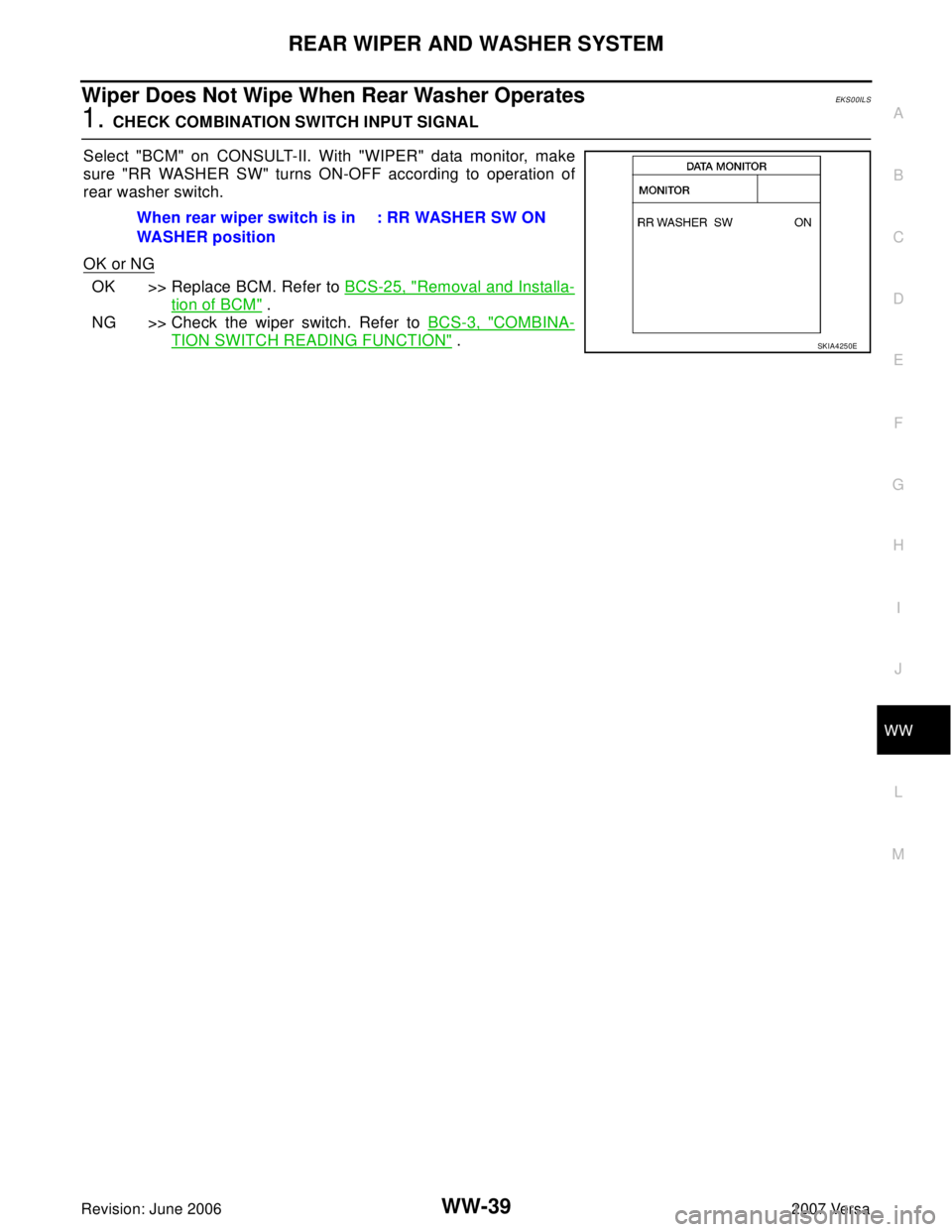
1. CHECK COMBINATION SWITCH INPUT SIGNAL
Select "BCM" on CONSULT-II. With "WIPER" data monitor, make
sure "RR WASHER SW" turns ON-OFF according to operation of
rear washer switch.
OK or NG
OK >> Replace BCM. Refer to BCS-25, "Removal and Installa-
tion of BCM" .
NG >> Check the wiper switch. Refer to BCS-3, "
COMBINA-
TION SWITCH READING FUNCTION" . When rear wiper switch is in
WASHER position: RR WASHER SW ONSKIA4250E
Page 2888 of 2896
WW-40
REAR WIPER AND WASHER SYSTEM
Revision: June 20062007 Versa
Removal and Installation EKS00ILT
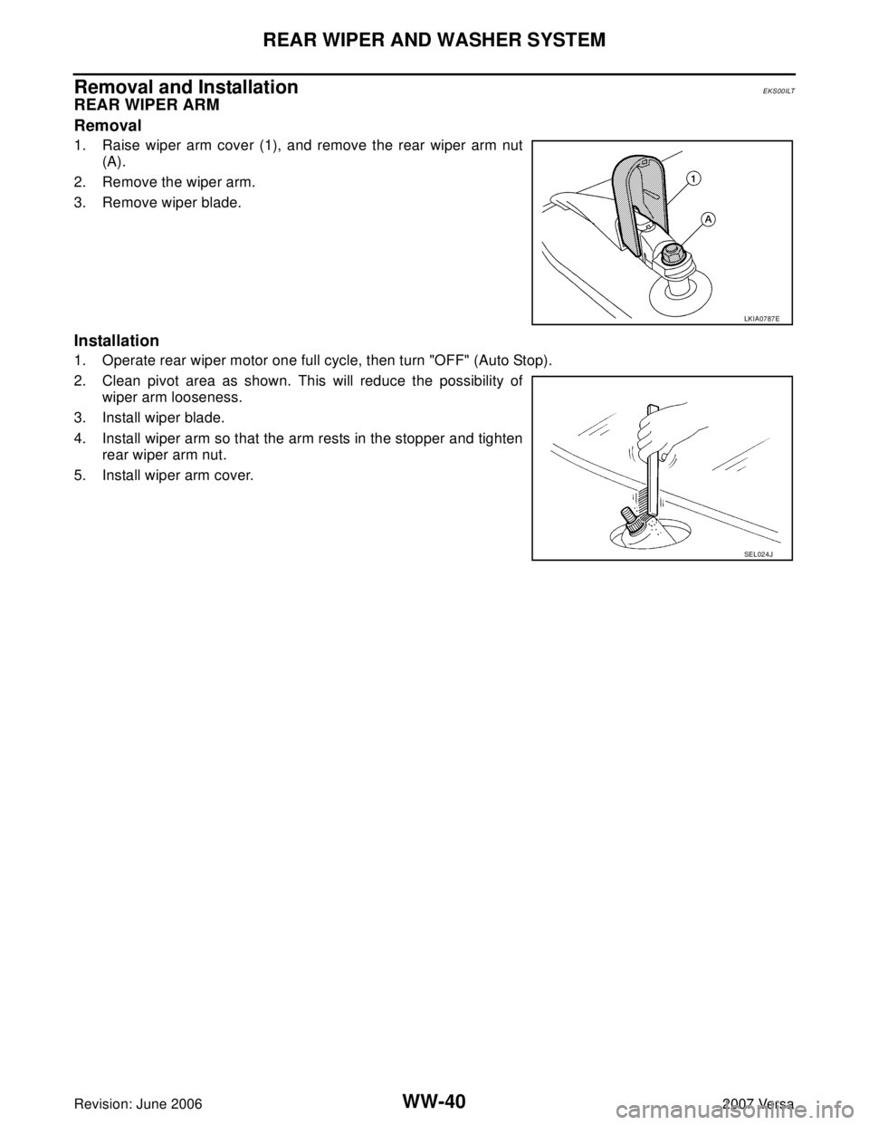
REAR WIPER ARM
Removal
1. Raise wiper arm cover (1), and remove the rear wiper arm nut
(A).
2. Remove the wiper arm.
3. Remove wiper blade.
Installation
1. Operate rear wiper motor one full cycle, then turn "OFF" (Auto Stop).
2. Clean pivot area as shown. This will reduce the possibility of
wiper arm looseness.
3. Install wiper blade.
4. Install wiper arm so that the arm rests in the stopper and tighten
rear wiper arm nut.
5. Install wiper arm cover.
LKIA0787E
SEL024J
Page 2889 of 2896
REAR WIPER AND WASHER SYSTEM
WW-41
C
D
E
F
G
H
I
J
L
MA
B
WW
Revision: June 20062007 Versa
REAR WIPER MOTOR
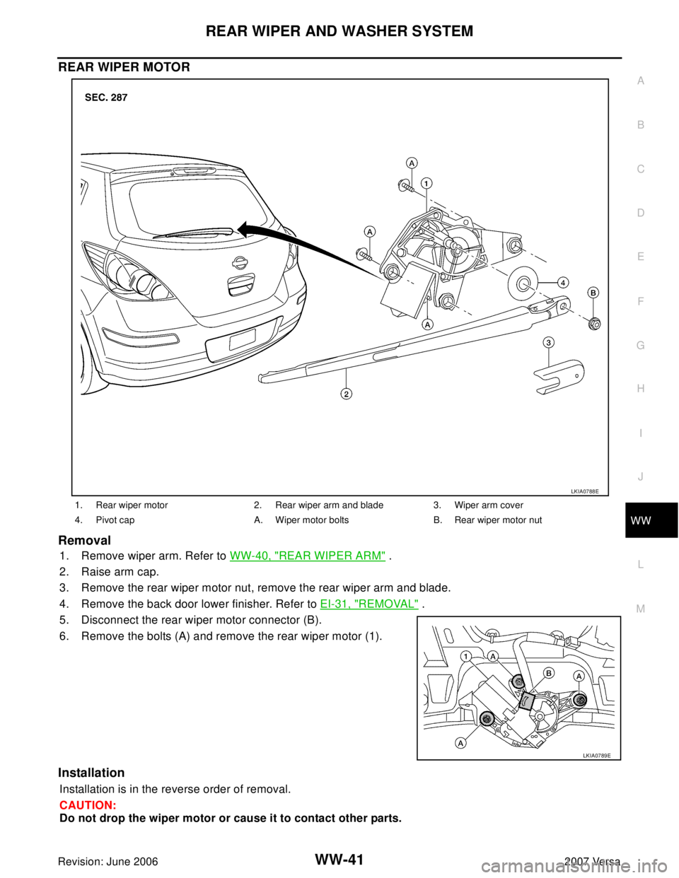
Removal
1. Remove wiper arm. Refer to WW-40, "REAR WIPER ARM" .
2. Raise arm cap.
3. Remove the rear wiper motor nut, remove the rear wiper arm and blade.
4. Remove the back door lower finisher. Refer to EI-31, "
REMOVAL" .
5. Disconnect the rear wiper motor connector (B).
6. Remove the bolts (A) and remove the rear wiper motor (1).
Installation
Installation is in the reverse order of removal.
CAUTION:
Do not drop the wiper motor or cause it to contact other parts.
1. Rear wiper motor 2. Rear wiper arm and blade 3. Wiper arm cover
4. Pivot cap A. Wiper motor bolts B. Rear wiper motor nut
LKIA0788E
LKIA0789E
Page 2890 of 2896
WW-42
REAR WIPER AND WASHER SYSTEM
Revision: June 20062007 Versa
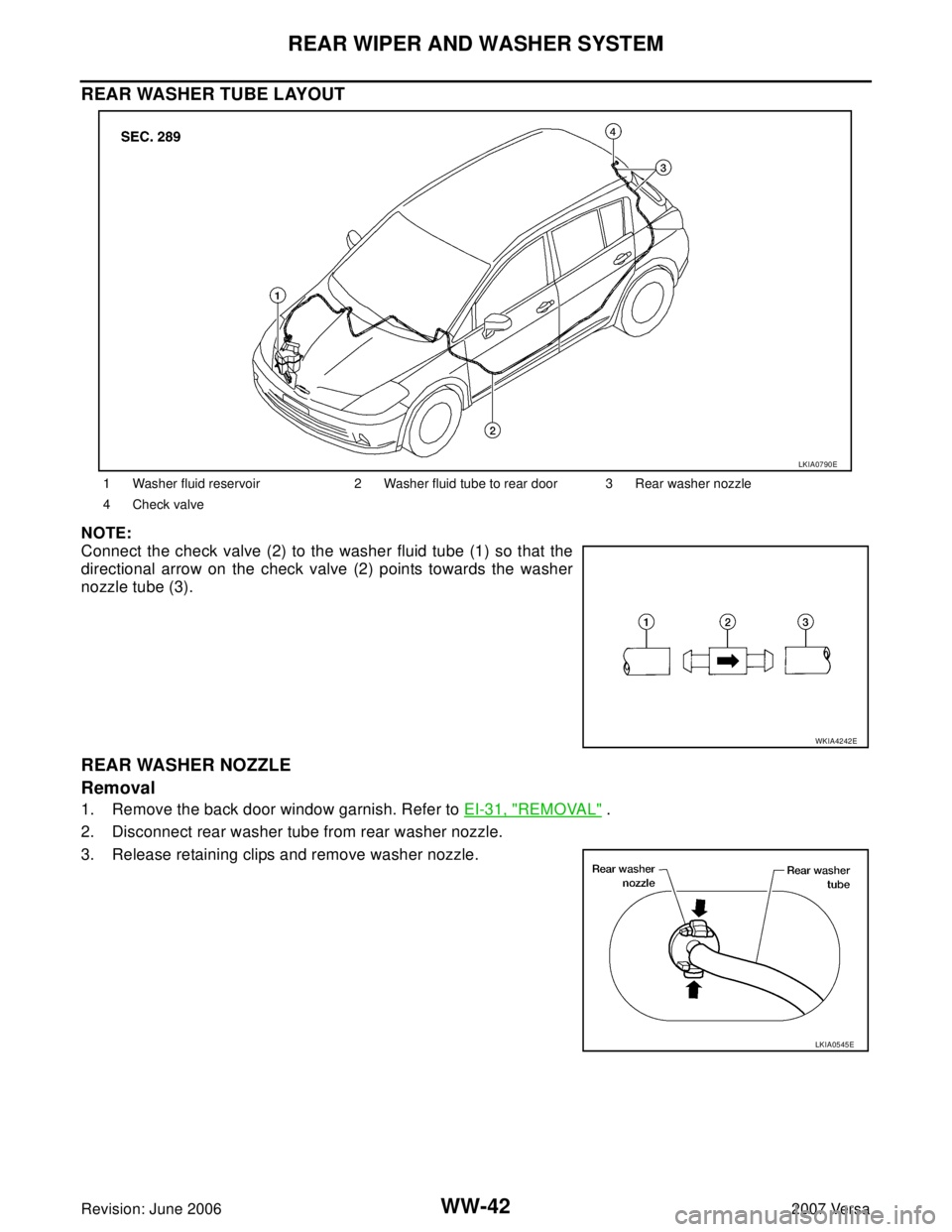
REAR WASHER TUBE LAYOUT
NOTE:
Connect the check valve (2) to the washer fluid tube (1) so that the
directional arrow on the check valve (2) points towards the washer
nozzle tube (3).
REAR WASHER NOZZLE
Removal
1. Remove the back door window garnish. Refer to EI-31, "REMOVAL" .
2. Disconnect rear washer tube from rear washer nozzle.
3. Release retaining clips and remove washer nozzle.
1 Washer fluid reservoir 2 Washer fluid tube to rear door 3 Rear washer nozzle
4 Check valve
LKIA0790E
WKIA4242E
LKIA0545E