tire pressure NISSAN LATIO 2008 Service User Guide
[x] Cancel search | Manufacturer: NISSAN, Model Year: 2008, Model line: LATIO, Model: NISSAN LATIO 2008Pages: 2771, PDF Size: 60.61 MB
Page 1840 of 2771
FSU-6
< SERVICE INFORMATION >
FRONT SUSPENSION ASSEMBLY
FRONT SUSPENSION ASSEMBLY
On-Vehicle Inspection and ServiceINFOID:0000000001703721
Make sure the mounting conditions (looseness, back lash) of each component and component conditions
(wear, damage) are normal.
INSPECTION OF LOWER BALL JOINT END PLAY
1. Set front wheels in a straight-ahead position. Do not depress brake pedal.
2. Place an iron bar or similar tool between transverse link and steering knuckle.
3. Measure axial end play by prying it up and down.
CAUTION:
Be careful not to damage ball joint boot. Do not damage the installation position by applying
excessive force.
STRUT INSPECTION
Check for oil leakage, damage and replace as necessary.
Wheel Alignment InspectionINFOID:0000000001703722
PRELIMINARY INSPECTION
WARNING:
Always adjust the alignment with the vehicle on a flat surface.
NOTE:
If alignment is out of specification, inspect and replace any damaged or worn rear suspension parts before
making any adjustments.
1. Check and adjust the wheel alignment with the vehicle under unladen conditions. “Unladen conditions”
means that the fuel, coolant, and lubricant are full; and that the spare tire, jack, hand tools and mats are in
their designated positions.
2. Check the tires for incorrect air pressure and excessive wear.
3. Check the wheels for run out and damage. Refer to WT-5, "
Inspection" .
4. Check the wheel bearing axial end play. Refer to FA X - 5 , "
On-Vehicle Inspection and Service" .
5. Check the shock absorbers for leaks or damage.
6. Check each mounting point of the suspension components for any excessive looseness or damage.
7. Check each link, arm, and the suspension member for any damage.
8. Check the vehicle height. Refer to FSU-17, "
Wheelarch Height (Unladen*)" .
GENERAL INFORMATION AND RECOMMENDATIONS
1. A Four-Wheel Thrust Alignment should be performed.
• This type of alignment is recommended for any NISSAN vehicle.
• The four-wheel “thrust” process helps ensure that the vehicle is properly aligned and the steering wheel
is centered.
• The alignment machine itself should be capable of accepting any NISSAN vehicle.
• The alignment machine should be checked to ensure that it is level.
2. Make sure the alignment machine is properly calibrated.
• Your alignment machine should be regularly calibrated in order to give correct information.
• Check with the manufacturer of your specific alignment machine for their recommended Service/Cali-
bration Schedule.
THE ALIGNMENT PROCESS
IMPORTANT: Use only the alignment specifications listed in this Service Manual. Refer to FSU-16, "Wheel
Alignment (Unladen*)" .
1. When displaying the alignment settings, many alignment machines use “indicators”: (Green/red, plus or
minus, Go/No Go). Do NOT use these indicators.
• The alignment specifications programmed into your alignment machine that operate these indicators
may not be correct.Axial end play : 0 mm (0 in)
Page 2015 of 2771
![NISSAN LATIO 2008 Service User Guide LAN-24
< FUNCTION DIAGNOSIS >[CAN]
CAN COMMUNICATION SYSTEM
Engine coolant temperature signal T R
Engine speed signal T R R
Engine status signal T R
Fuel consumption monitor signal T R
Malfunction ind NISSAN LATIO 2008 Service User Guide LAN-24
< FUNCTION DIAGNOSIS >[CAN]
CAN COMMUNICATION SYSTEM
Engine coolant temperature signal T R
Engine speed signal T R R
Engine status signal T R
Fuel consumption monitor signal T R
Malfunction ind](/img/5/57360/w960_57360-2014.png)
LAN-24
< FUNCTION DIAGNOSIS >[CAN]
CAN COMMUNICATION SYSTEM
Engine coolant temperature signal T R
Engine speed signal T R R
Engine status signal T R
Fuel consumption monitor signal T R
Malfunction indicator lamp signal T R
Wide open throttle position signal T R R
A/C switch signal R T
Blower fan motor switch signal R T
Buzzer output signalTR
TR
Day time running light request signal
*3TR R
Door lock/unlock status signal T R
Door switch signal T R R R
Front wiper request signal T R
High beam request signal T R R
Horn chirp signal T R
Ignition switch signal T R
Low beam request signal T R
Position lights request signal T R R
Rear window defogger switch signal T R
Sleep/wake up signalRT
TRR R
Theft warning horn request signal T R
Tire pressure signal
*4TR
Trunk open/close status signal T R
Turn indicator signal T R
EPS operation signal R T
EPS warning lamp signal T R
Door lock/unlock/trunk open request signal R T
Hazard request signal R T
Ignition knob switch signal R T
KEY warning lamp signal T R
LOCK warning lamp signal T R
Panic alarm request signal R T
Fuel level sensor signal R T
Overdrive control switch signal T R R
P/N range signal T R
Stop lamp switch signal T R R
Vehicle speed signalRRR T
RRRT R
R
*5R*5T*5
ABS warning lamp signal R TSignal name/Connecting unit
ECM
BCM
EPS
I-KEY
M&A
ABS
TCM
*1
TCM
*2
IPDM-E
Page 2158 of 2771
HEADLAMP (FOR USA)
LT-21
< SERVICE INFORMATION >
C
D
E
F
G
H
I
J
L
MA
B
LT
N
O
P
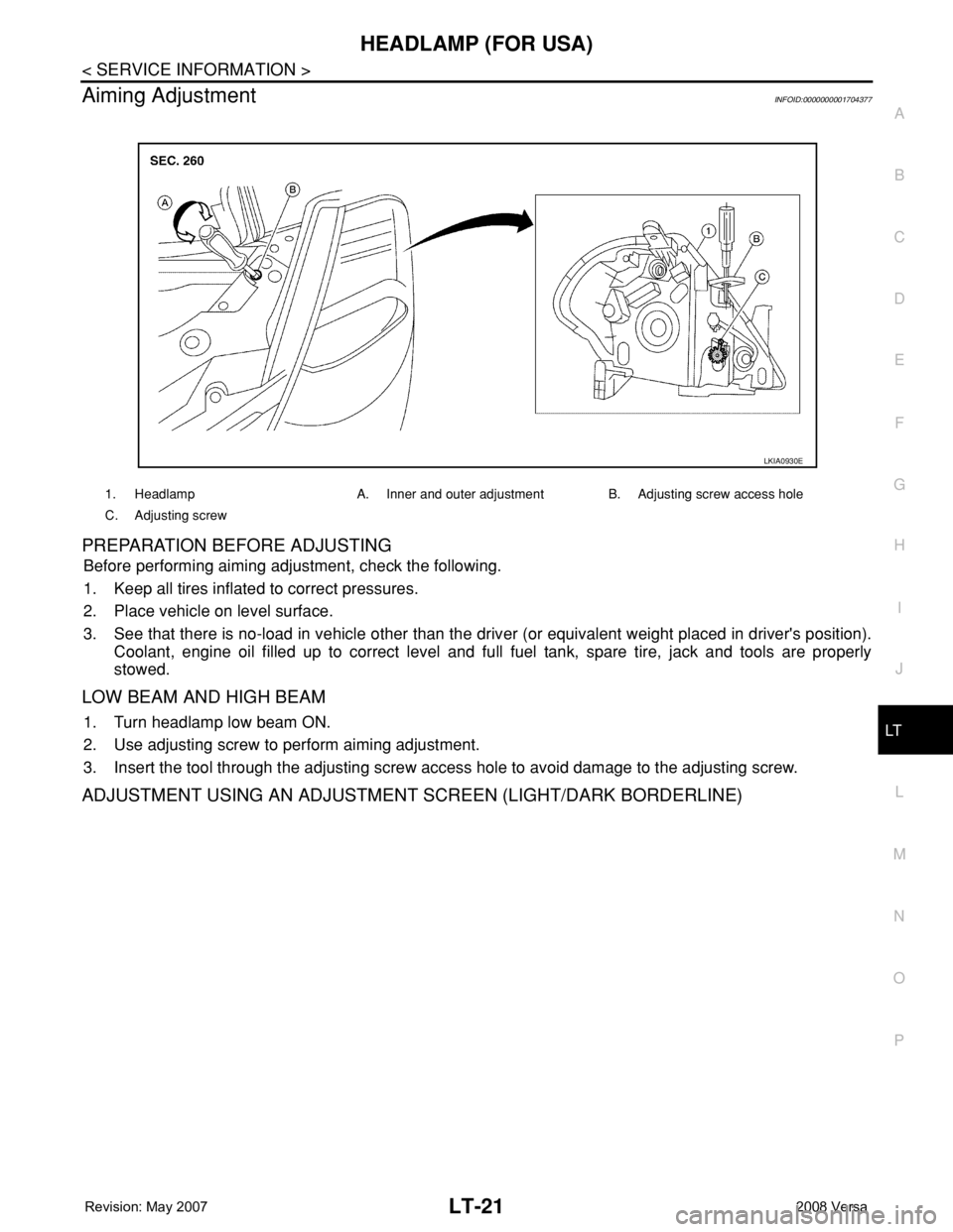
Aiming AdjustmentINFOID:0000000001704377
PREPARATION BEFORE ADJUSTING
Before performing aiming adjustment, check the following.
1. Keep all tires inflated to correct pressures.
2. Place vehicle on level surface.
3. See that there is no-load in vehicle other than the driver (or equivalent weight placed in driver's position).
Coolant, engine oil filled up to correct level and full fuel tank, spare tire, jack and tools are properly
stowed.
LOW BEAM AND HIGH BEAM
1. Turn headlamp low beam ON.
2. Use adjusting screw to perform aiming adjustment.
3. Insert the tool through the adjusting screw access hole to avoid damage to the adjusting screw.
ADJUSTMENT USING AN ADJUSTMENT SCREEN (LIGHT/DARK BORDERLINE)
1. Headlamp A. Inner and outer adjustment B. Adjusting screw access hole
C. Adjusting screw
LKIA0930E
Page 2172 of 2771
HEADLAMP (FOR CANADA) - DAYTIME LIGHT SYSTEM -
LT-35
< SERVICE INFORMATION >
C
D
E
F
G
H
I
J
L
MA
B
LT
N
O
P
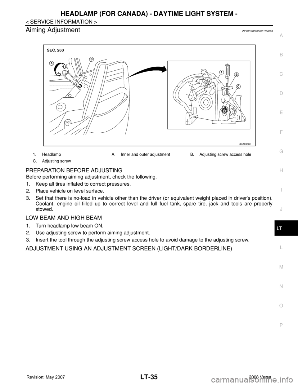
Aiming AdjustmentINFOID:0000000001704393
PREPARATION BEFORE ADJUSTING
Before performing aiming adjustment, check the following.
1. Keep all tires inflated to correct pressures.
2. Place vehicle on level surface.
3. Set that there is no-load in vehicle other than the driver (or equivalent weight placed in driver's position).
Coolant, engine oil filled up to correct level and full fuel tank, spare tire, jack and tools are properly
stowed.
LOW BEAM AND HIGH BEAM
1. Turn headlamp low beam ON.
2. Use adjusting screw to perform aiming adjustment.
3. Insert the tool through the adjusting screw access hole to avoid damage to the adjusting screw.
ADJUSTMENT USING AN ADJUSTMENT SCREEN (LIGHT/DARK BORDERLINE)
1. Headlamp A. Inner and outer adjustment B. Adjusting screw access hole
C. Adjusting screw
LKIA0930E
Page 2183 of 2771
LT-46
< SERVICE INFORMATION >
FRONT FOG LAMP
1. Check continuity between front fog lamp harness connector and
ground.
OK or NG
OK >> Replace IPDM E/R. Refer to PG-26, "Removal and
Installation of IPDM E/R" .
NG >> Repair harness or connector.
Aiming AdjustmentINFOID:0000000001704409
The front fog lamp is a semi-sealed beam type which uses a replaceable halogen bulb. Before performing
aiming adjustment, make sure of the following.
• Keep all tires inflated to correct pressure.
• Place vehicle on level surface.
• Set that there is no-load in vehicle other than the driver (or equivalent weight placed in driver’s position).
Coolant, engine oil filled up to correct level and full fuel tank, spare tire, jack and tools are properly stowed.
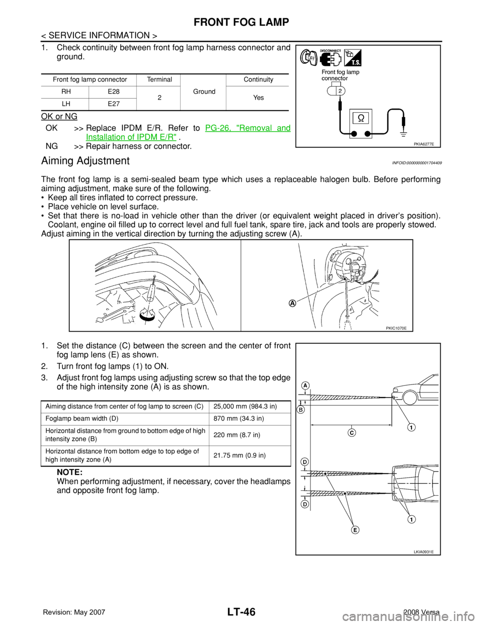
Adjust aiming in the vertical direction by turning the adjusting screw (A).
1. Set the distance (C) between the screen and the center of front
fog lamp lens (E) as shown.
2. Turn front fog lamps (1) to ON.
3. Adjust front fog lamps using adjusting screw so that the top edge
of the high intensity zone (A) is as shown.
NOTE:
When performing adjustment, if necessary, cover the headlamps
and opposite front fog lamp.
Front fog lamp connector Terminal
Ground Continuity
RH E28
2Yes
LH E27
PKIA6277E
PKIC1070E
Aiming distance from center of fog lamp to screen (C) 25,000 mm (984.3 in)
Foglamp beam width (D) 870 mm (34.3 in)
Horizontal distance from ground to bottom edge of high
intensity zone (B)220 mm (8.7 in)
Horizontal distance from bottom edge to top edge of
high intensity zone (A)21.75 mm (0.9 in)
LKIA0931E
Page 2264 of 2771
MA-4
< SERVICE INFORMATION >
GENERAL MAINTENANCE
GENERAL MAINTENANCE
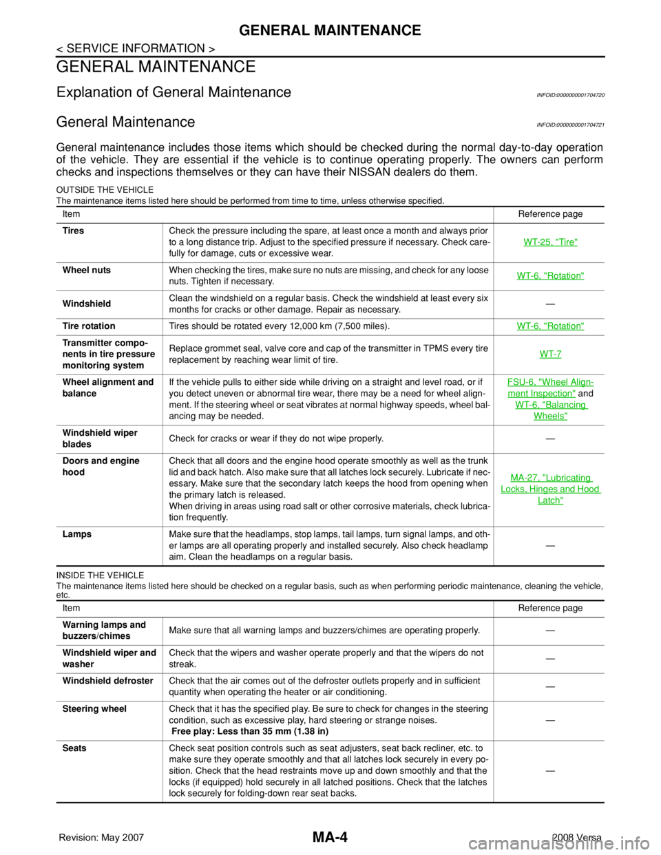
Explanation of General MaintenanceINFOID:0000000001704720
General MaintenanceINFOID:0000000001704721
General maintenance includes those items which should be checked during the normal day-to-day operation
of the vehicle. They are essential if the vehicle is to continue operating properly. The owners can perform
checks and inspections themselves or they can have their NISSAN dealers do them.
OUTSIDE THE VEHICLE
The maintenance items listed here should be performed from time to time, unless otherwise specified.
INSIDE THE VEHICLE
The maintenance items listed here should be checked on a regular basis, such as when performing periodic maintenance, cleaning the vehicle,
etc.
ItemReference page
TiresCheck the pressure including the spare, at least once a month and always prior
to a long distance trip. Adjust to the specified pressure if necessary. Check care-
fully for damage, cuts or excessive wear.WT-25, "
Tire"
Wheel nutsWhen checking the tires, make sure no nuts are missing, and check for any loose
nuts. Tighten if necessary.WT-6, "Rotation"
WindshieldClean the windshield on a regular basis. Check the windshield at least every six
months for cracks or other damage. Repair as necessary.—
Tire rotationTires should be rotated every 12,000 km (7,500 miles).WT-6, "
Rotation"
Transmitter compo-
nents in tire pressure
monitoring systemReplace grommet seal, valve core and cap of the transmitter in TPMS every tire
replacement by reaching wear limit of tire.WT-7
Wheel alignment and
balanceIf the vehicle pulls to either side while driving on a straight and level road, or if
you detect uneven or abnormal tire wear, there may be a need for wheel align-
ment. If the steering wheel or seat vibrates at normal highway speeds, wheel bal-
ancing may be needed.FSU-6, "Wheel Align-
ment Inspection" and
WT-6, "
Balancing
Wheels"
Windshield wiper
bladesCheck for cracks or wear if they do not wipe properly. —
Doors and engine
hoodCheck that all doors and the engine hood operate smoothly as well as the trunk
lid and back hatch. Also make sure that all latches lock securely. Lubricate if nec-
essary. Make sure that the secondary latch keeps the hood from opening when
the primary latch is released.
When driving in areas using road salt or other corrosive materials, check lubrica-
tion frequently.MA-27, "
Lubricating
Locks, Hinges and Hood
Latch"
LampsMake sure that the headlamps, stop lamps, tail lamps, turn signal lamps, and oth-
er lamps are all operating properly and installed securely. Also check headlamp
aim. Clean the headlamps on a regular basis.—
ItemReference page
Warning lamps and
buzzers/chimesMake sure that all warning lamps and buzzers/chimes are operating properly. —
Windshield wiper and
washerCheck that the wipers and washer operate properly and that the wipers do not
streak.—
Windshield defrosterCheck that the air comes out of the defroster outlets properly and in sufficient
quantity when operating the heater or air conditioning.—
Steering wheelCheck that it has the specified play. Be sure to check for changes in the steering
condition, such as excessive play, hard steering or strange noises.
Free play: Less than 35 mm (1.38 in)—
SeatsCheck seat position controls such as seat adjusters, seat back recliner, etc. to
make sure they operate smoothly and that all latches lock securely in every po-
sition. Check that the head restraints move up and down smoothly and that the
locks (if equipped) hold securely in all latched positions. Check that the latches
lock securely for folding-down rear seat backs.—
Page 2272 of 2771
MA-12
< SERVICE INFORMATION >
ENGINE MAINTENANCE
ENGINE MAINTENANCE
Drive BeltsINFOID:0000000001704728
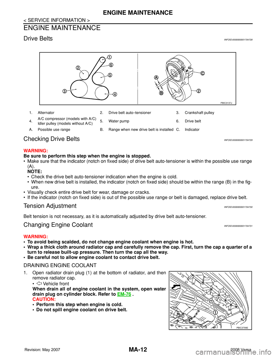
Checking Drive BeltsINFOID:0000000001704729
WARNING:
Be sure to perform this step when the engine is stopped.
• Make sure that the indicator (notch on fixed side) of drive belt auto-tensioner is within the possible use range
(A).
NOTE:
• Check the drive belt auto-tensioner indication when the engine is cold.
• When new drive belt is installed, the indicator (notch on fixed side) should be within the range (B) in the fig-
ure.
• Visually check entire drive belt for wear, damage or cracks.
• If the indicator (notch on fixed side) is out of the possible use range or belt is damaged, replace drive belt.
Tension AdjustmentINFOID:0000000001704730
Belt tension is not necessary, as it is automatically adjusted by drive belt auto-tensioner.
Changing Engine CoolantINFOID:0000000001704731
WARNING:
• To avoid being scalded, do not change engine coolant when engine is hot.
• Wrap a thick cloth around radiator cap and carefully remove the cap. First, turn the cap a quarter of a
turn to release built-up pressure. Then turn the cap all the way.
• Be careful not to allow engine coolant to contact drive belt.
DRAINING ENGINE COOLANT
1. Open radiator drain plug (1) at the bottom of radiator, and then
remove radiator cap.
• Vehicle front
When drain all of engine coolant in the system, open water
drain plug on cylinder block. Refer to EM-76
.
CAUTION:
• Perform this step when engine is cold.
• Do not spill engine coolant on drive belt.
1. Alternator 2. Drive belt auto–tensioner 3. Crankshaft pulley
4.A/C compressor (models with A/C)
Idler pulley (models without A/C)5. Water pump 6. Drive belt
A. Possible use range B. Range when new drive belt is installed C. Indicator
PBIC3137J
PBIC3799E
Page 2417 of 2771
REFRIGERANT LINES
MTC-79
< SERVICE INFORMATION >
C
D
E
F
G
H
I
K
L
MA
B
MTC
N
O
P
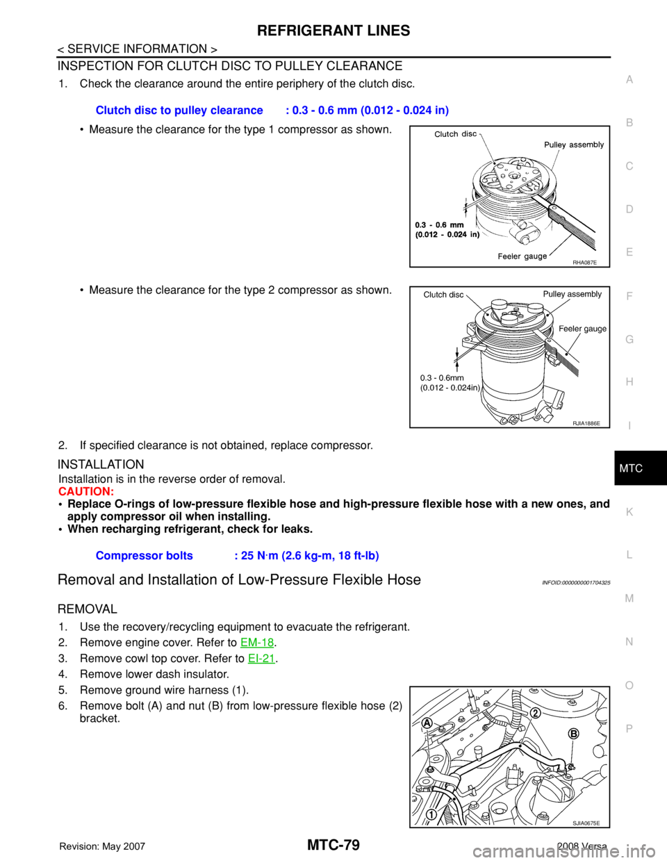
INSPECTION FOR CLUTCH DISC TO PULLEY CLEARANCE
1. Check the clearance around the entire periphery of the clutch disc.
• Measure the clearance for the type 1 compressor as shown.
• Measure the clearance for the type 2 compressor as shown.
2. If specified clearance is not obtained, replace compressor.
INSTALLATION
Installation is in the reverse order of removal.
CAUTION:
• Replace O-rings of low-pressure flexible hose and high-pressure flexible hose with a new ones, and
apply compressor oil when installing.
• When recharging refrigerant, check for leaks.
Removal and Installation of Low-Pressure Flexible HoseINFOID:0000000001704325
REMOVAL
1. Use the recovery/recycling equipment to evacuate the refrigerant.
2. Remove engine cover. Refer to EM-18
.
3. Remove cowl top cover. Refer to EI-21
.
4. Remove lower dash insulator.
5. Remove ground wire harness (1).
6. Remove bolt (A) and nut (B) from low-pressure flexible hose (2)
bracket.Clutch disc to pulley clearance : 0.3 - 0.6 mm (0.012 - 0.024 in)
RHA087E
RJIA1886E
Compressor bolts : 25 N·m (2.6 kg-m, 18 ft-lb)
SJIA0675E
Page 2472 of 2771

HARNESS
PG-39
< SERVICE INFORMATION >
C
D
E
F
G
H
I
J
L
MA
B
PG
N
O
P
C2 M6 W/4 : Steering lock solenoid E2 M52 W/40 : Intelligent key unit
B3 M7 W/16 : Door mirror remote control switch B2 M53 W/16 : EPS control unit
A3 M8 W/16 : To D2 B3 M54 B/2 : EPS control unit
A3 M9 W/16 : To D1 C3 M55† W/4: Hazard switch (hatchback early
production)
E2 M10 GR/2 : Instrument panel antenna D2 M55†† W/4: Hazard switch (hatchback late production
or sedan)
G3 M11 W/4 : To B106 B2 M57 — : Body ground
G4 M12 W/16 : To B101 F2 M59 W/2 : Glove box lamp
G3 M13 W/24 : To B102 C1 M60 L/2 : EPS control unit
G3 M14 W/24 : To B120 F1 M61 — : Body ground
B4 M15 W/16 : To B23 E2 M62 W/2 : Front blower motor
B4 M16 W/24 : To B24 C1 M63 W/4 : Torque sensor
D5 M17 B/1 : Parking brake switch A2 M69 SMJ : To E7
F2 M18 W/40 : BCM (body control module) B2 M73 GR/6: Key switch and ignition knob switch (With
intelligent key)
F2 M19 W/15 : BCM (body control module) G3 M74 W/12 : To D102
F3 M20 B/15 : BCM (body control module) G3 M75 W/12 : To D101
C2 M21 W/4 : NATS antenna amp. F2 M77 Y/4 : Front passenger air bag module
B3 M22 W/16 : Data link connector A2 M78 B/2 : To E11
E3 M23 W/4 : Remote keyless entry receiver B1 M79 — : Body ground
C1 M24 W/40 : Combination meter D3 M150 W/4 : To M32
C3 M25 /2 : Diode-1 C3 M151 W/4 : Front blower motor resistor
B2 M26 W/6 : Ignition switch
C2 M27 GR/6 : Key switch and key lock solenoid
C2 M28 W/16 : Combination switch
C3 M29 Y/6 : Combination switch (spiral cable)
C3 M30 GR/8 : Combination switch (spiral cable)
E3 M32 W/4 : To M150
D2 M33 B/15 : Front air control
D4 M35 Y/28 : Air bag diagnosis sensor unit
D2 M36† W/3: Front passenger air bag OFF indicator
(hatchback early production)
C3 M36†† W/3: Front passenger air bag OFF indicator
(hatchback late production or sedan)
D4 M38 W/6 : A/T device
D4 M38 W/6 : CVT device (without intelligent key)
D4 M38 W/8 : CVT device (with intelligent key)
B3 M39 W/2 : Tire pressure warning check connector
D2 M41 W/2 : Defrost A/C switch
D3 M42 W/3 : Thermo control amp. (without CVT)
D2 M43 W/20 : Audio unit
Page 2493 of 2771

PG-60
< SERVICE INFORMATION >
HARNESS
SEN/PW EC Sensor Power Supply
SESCVT CVT Secondary Pressure Sensor Solenoid Valve
SHIFT AT A/T Shift Lock System
SHIFT CVT CVT Shift Lock System
SROOF RF Sunroof
SRS SRS Supplemental Restraint System
SSV/A AT Shift Solenoid Valve A
SSV/B AT Shift Solenoid Valve B
START SC Starting System
STM CVT Step Motor
STSIG CVT Start Signal Circuit
STOP/L LT Stop Lamp
TCV AT Torque Converter Clutch Solenoid Valve
TCV CVT Torque Converter Clutch Solenoid Valve
T/LID BL Trunk Lid Opener
T/WARN WT Low Tire Pressure Warning System
TAIL/L LT Parking, License and Tail Lamps
TPS1 EC Throttle Position Sensor
TPS2 EC Throttle Position Sensor
TPS3 EC Throttle Position Sensor
TURN LT Turn Signal and Hazard Warning Lamps
VEHSEC BL Vehicle Security (Theft Warning) System
VENT/V EC EVAP Canister Vent Control Valve
VSSA/T AT Vehicle Speed Sensor A/T (Revolution Sensor)
VSSMTR AT Vehicle Speed Sensor MTR
WARN DI Warning Lamps
WINDOW GW Power Window
WIP/R WW Rear Wiper and Washer
WIPER WW Front Wiper and Washer