dimensions NISSAN LATIO 2008 Service Repair Manual
[x] Cancel search | Manufacturer: NISSAN, Model Year: 2008, Model line: LATIO, Model: NISSAN LATIO 2008Pages: 2771, PDF Size: 60.61 MB
Page 333 of 2771
ASSEMBLY
AT-321
< SERVICE INFORMATION >
D
E
F
G
H
I
J
K
L
MA
B
AT
N
O
P
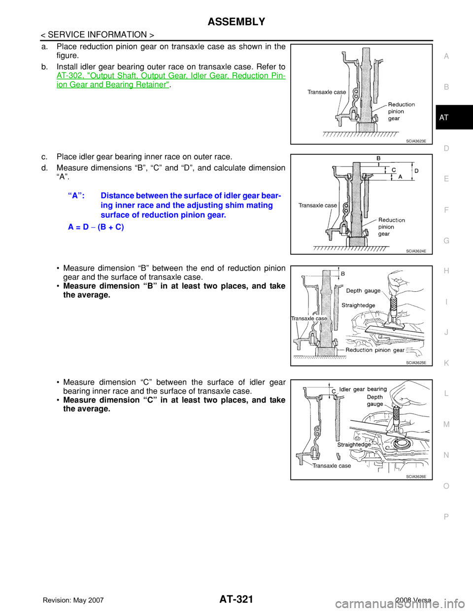
a. Place reduction pinion gear on transaxle case as shown in the
figure.
b. Install idler gear bearing outer race on transaxle case. Refer to
AT-302, "
Output Shaft, Output Gear, Idler Gear, Reduction Pin-
ion Gear and Bearing Retainer".
c. Place idler gear bearing inner race on outer race.
d. Measure dimensions “B”, “C” and “D”, and calculate dimension
“A”.
• Measure dimension “B” between the end of reduction pinion
gear and the surface of transaxle case.
•Measure dimension “B” in at least two places, and take
the average.
• Measure dimension “C” between the surface of idler gear
bearing inner race and the surface of transaxle case.
•Measure dimension “C” in at least two places, and take
the average.
SCIA3623E
“A”: Distance between the surface of idler gear bear-
ing inner race and the adjusting shim mating
surface of reduction pinion gear.
A = D − (B + C)
SCIA3624E
SCIA3625E
SCIA3626E
Page 336 of 2771
AT-324
< SERVICE INFORMATION >
ASSEMBLY
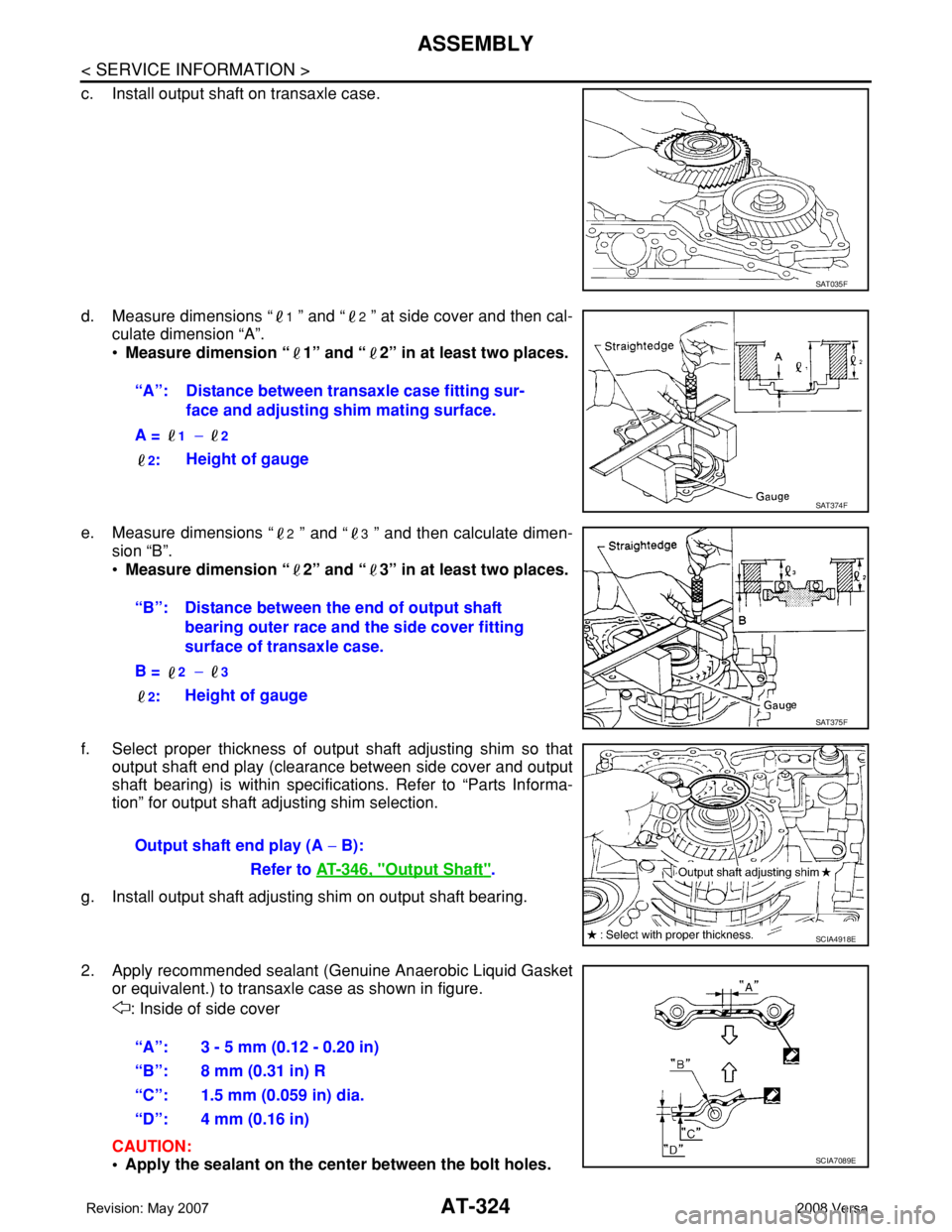
c. Install output shaft on transaxle case.
d. Measure dimensions “
1 ” and “2 ” at side cover and then cal-
culate dimension “A”.
•Measure dimension “ 1” and “ 2” in at least two places.
e. Measure dimensions “
2 ” and “3 ” and then calculate dimen-
sion “B”.
•Measure dimension “ 2” and “ 3” in at least two places.
f. Select proper thickness of output shaft adjusting shim so that
output shaft end play (clearance between side cover and output
shaft bearing) is within specifications. Refer to “Parts Informa-
tion” for output shaft adjusting shim selection.
g. Install output shaft adjusting shim on output shaft bearing.
2. Apply recommended sealant (Genuine Anaerobic Liquid Gasket
or equivalent.) to transaxle case as shown in figure.
: Inside of side cover
CAUTION:
• Apply the sealant on the center between the bolt holes.
SAT035F
“A”: Distance between transaxle case fitting sur-
face and adjusting shim mating surface.
A =
1 − 2
2
:Height of gauge
SAT374F
“B”: Distance between the end of output shaft
bearing outer race and the side cover fitting
surface of transaxle case.
B =
2 − 3
2
:Height of gauge
SAT375F
Output shaft end play (A − B):
Refer to AT-346, "
Output Shaft".
SCIA4918E
“A”: 3 - 5 mm (0.12 - 0.20 in)
“B”: 8 mm (0.31 in) R
“C”: 1.5 mm (0.059 in) dia.
“D”: 4 mm (0.16 in)
SCIA7089E
Page 342 of 2771

AT-330
< SERVICE INFORMATION >
ASSEMBLY
Adjustment (2)
INFOID:0000000001703394
When any parts listed below are replaced, adjust total end play and reverse clutch end play.
TOTAL END PLAY
• Measure clearance between reverse clutch drum and needle bear-
ing for oil pump cover.
• Select proper thickness of bearing race so that end play is within
specifications.
1. Measure dimensions “K” and “L”, and then calculate dimension
“J”.
a. Measure dimension “K”.
Part name Total end play Reverse clutch end play
Transaxle case●●
Overrun clutch hub●●
Rear internal gear●●
Rear planetary carrier●●
Rear sun gear●●
Front planetary carrier●●
Front sun gear●●
High clutch hub●●
Input shaft assembly (high clutch drum)●●
Oil pump cover●●
Reverse clutch drum —●
SCIA3661E
SCIA3662E
SCIA3663E
Page 344 of 2771

AT-332
< SERVICE INFORMATION >
ASSEMBLY
• Measure clearance between oil pump cover and thrust washer for
reverse clutch drum.
• Select proper thickness of thrust washer so that end play is within
specification.
1. Measure dimensions “O” and “P”, and then calculate dimension
“N”.
a. Place thrust washer on reverse clutch drum.
b. Measure dimension “O”.
c. Measure dimension “P”.
d. Calculate dimension “N”.
2. Measure dimensions “R” and “S”, and then calculate dimension
“Q”.
SCIA3665E
SCIA3666E
SCIA3667E
“N”: Distance between oil pump fitting surface of
transaxle case and thrust washer on reverse
clutch drum.
N = O – P
SCIA3668E
SAT384D
Page 682 of 2771
BL-248
< SERVICE INFORMATION >
BODY REPAIR
Sedan
DESCRIPTION
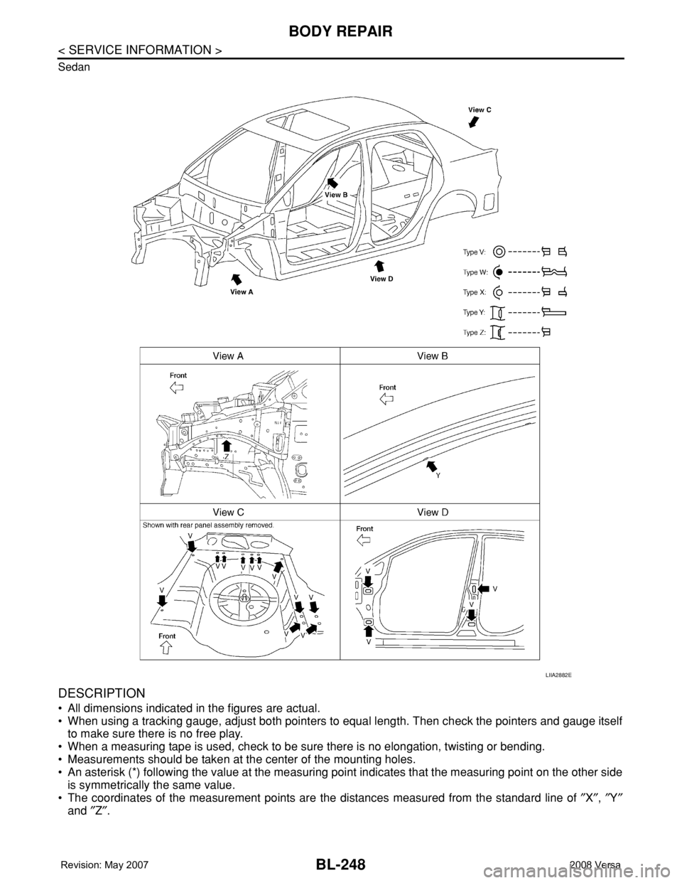
• All dimensions indicated in the figures are actual.
• When using a tracking gauge, adjust both pointers to equal length. Then check the pointers and gauge itself
to make sure there is no free play.
• When a measuring tape is used, check to be sure there is no elongation, twisting or bending.
• Measurements should be taken at the center of the mounting holes.
• An asterisk (*) following the value at the measuring point indicates that the measuring point on the other side
is symmetrically the same value.
• The coordinates of the measurement points are the distances measured from the standard line of ″X″, ″Y″
and ″Z″.
LIIA2882E
Page 820 of 2771
PRECAUTIONS
CO-3
< SERVICE INFORMATION >
C
D
E
F
G
H
I
J
K
L
MA
CO
N
P O
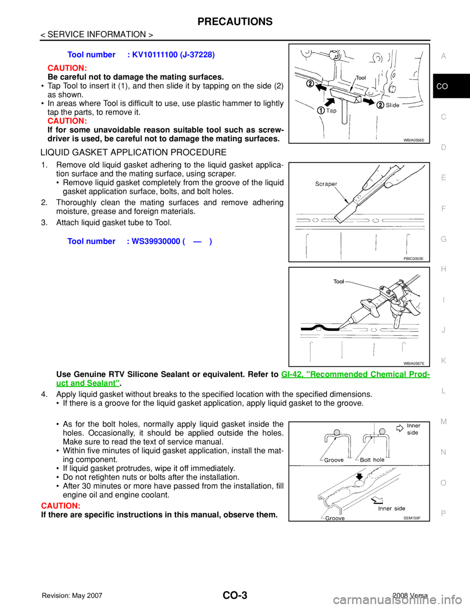
CAUTION:
Be careful not to damage the mating surfaces.
• Tap Tool to insert it (1), and then slide it by tapping on the side (2)
as shown.
• In areas where Tool is difficult to use, use plastic hammer to lightly
tap the parts, to remove it.
CAUTION:
If for some unavoidable reason suitable tool such as screw-
driver is used, be careful not to damage the mating surfaces.
LIQUID GASKET APPLICATION PROCEDURE
1. Remove old liquid gasket adhering to the liquid gasket applica-
tion surface and the mating surface, using scraper.
• Remove liquid gasket completely from the groove of the liquid
gasket application surface, bolts, and bolt holes.
2. Thoroughly clean the mating surfaces and remove adhering
moisture, grease and foreign materials.
3. Attach liquid gasket tube to Tool.
Use Genuine RTV Silicone Sealant or equivalent. Refer to GI-42, "
Recommended Chemical Prod-
uct and Sealant".
4. Apply liquid gasket without breaks to the specified location with the specified dimensions.
• If there is a groove for the liquid gasket application, apply liquid gasket to the groove.
• As for the bolt holes, normally apply liquid gasket inside the
holes. Occasionally, it should be applied outside the holes.
Make sure to read the text of service manual.
• Within five minutes of liquid gasket application, install the mat-
ing component.
• If liquid gasket protrudes, wipe it off immediately.
• Do not retighten nuts or bolts after the installation.
• After 30 minutes or more have passed from the installation, fill
engine oil and engine coolant.
CAUTION:
If there are specific instructions in this manual, observe them. Tool number : KV10111100 (J-37228)
WBIA0566E
Tool number : WS39930000 ( — )
PBIC0003E
WBIA0567E
SEM159F
Page 1016 of 2771
DIFFERENTIAL SIDE OIL SEAL
CVT-177
< SERVICE INFORMATION >
D
E
F
G
H
I
J
K
L
MA
B
CVT
N
O
P
DIFFERENTIAL SIDE OIL SEAL
Removal and InstallationINFOID:0000000001703686
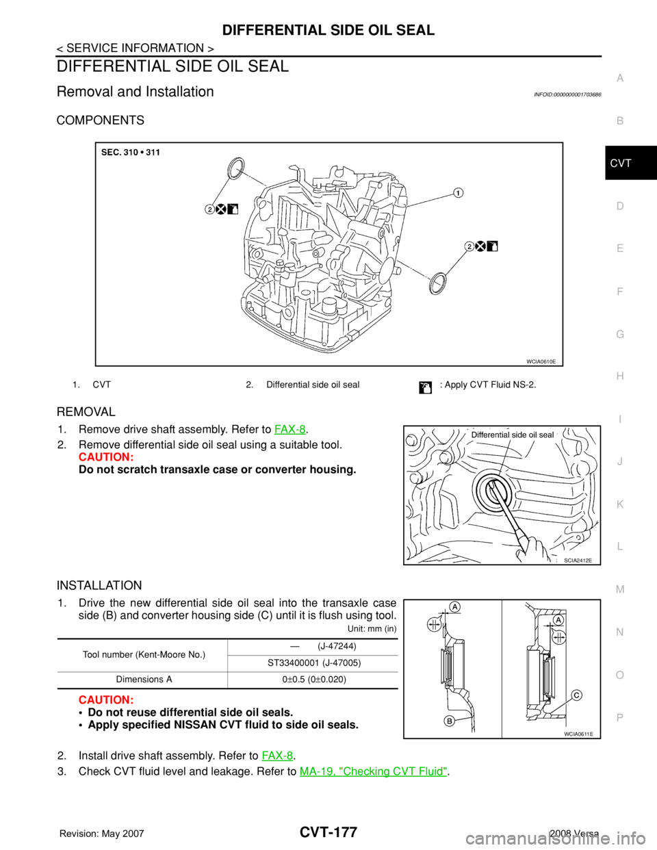
COMPONENTS
REMOVAL
1. Remove drive shaft assembly. Refer to FA X - 8.
2. Remove differential side oil seal using a suitable tool.
CAUTION:
Do not scratch transaxle case or converter housing.
INSTALLATION
1. Drive the new differential side oil seal into the transaxle case
side (B) and converter housing side (C) until it is flush using tool.
Unit: mm (in)
CAUTION:
• Do not reuse differential side oil seals.
• Apply specified NISSAN CVT fluid to side oil seals.
2. Install drive shaft assembly. Refer to FA X - 8
.
3. Check CVT fluid level and leakage. Refer to MA-19, "
Checking CVT Fluid".
1. CVT 2. Differential side oil seal : Apply CVT Fluid NS-2.
WCIA0610E
SCIA2412E
Tool number (Kent-Moore No.)— (J-47244)
ST33400001 (J-47005)
Dimensions A 0±0.5 (0±0.020)
WCIA0611E
Page 1686 of 2771
PREPARATION
EM-9
< SERVICE INFORMATION >
C
D
E
F
G
H
I
J
K
L
MA
EM
N
P O
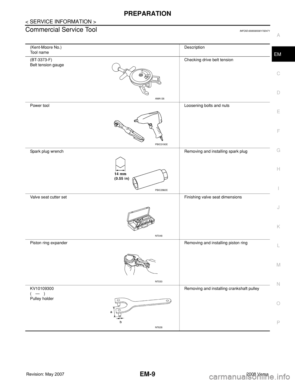
Commercial Service ToolINFOID:0000000001702471
(Kent-Moore No.)
Tool nameDescription
(BT-3373-F)
Belt tension gaugeChecking drive belt tension
Power toolLoosening bolts and nuts
Spark plug wrench Removing and installing spark plug
Valve seat cutter set Finishing valve seat dimensions
Piston ring expander Removing and installing piston ring
KV10109300
(—)
Pulley holderRemoving and installing crankshaft pulley
AMA126
PBIC0190E
PBIC2982E
NT048
NT030
NT628
Page 1705 of 2771
EM-28
< SERVICE INFORMATION >
OIL PAN
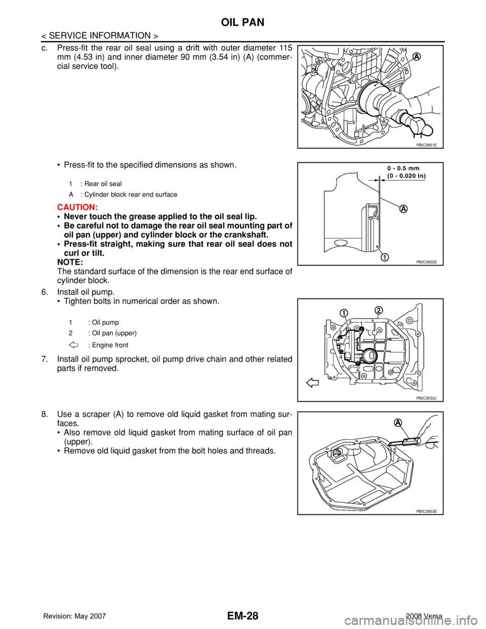
c. Press-fit the rear oil seal using a drift with outer diameter 115
mm (4.53 in) and inner diameter 90 mm (3.54 in) (A) (commer-
cial service tool).
• Press-fit to the specified dimensions as shown.
CAUTION:
• Never touch the grease applied to the oil seal lip.
• Be careful not to damage the rear oil seal mounting part of
oil pan (upper) and cylinder block or the crankshaft.
• Press-fit straight, making sure that rear oil seal does not
curl or tilt.
NOTE:
The standard surface of the dimension is the rear end surface of
cylinder block.
6. Install oil pump.
• Tighten bolts in numerical order as shown.
7. Install oil pump sprocket, oil pump drive chain and other related
parts if removed.
8. Use a scraper (A) to remove old liquid gasket from mating sur-
faces.
• Also remove old liquid gasket from mating surface of oil pan
(upper).
• Remove old liquid gasket from the bolt holes and threads.
PBIC3951E
1 : Rear oil seal
A : Cylinder block rear end surface
1 : Oil pump
2 : Oil pan (upper)
: Engine front
PBIC3952E
PBIC3532J
PBIC3953E
Page 1744 of 2771
CYLINDER HEAD
EM-67
< SERVICE INFORMATION >
C
D
E
F
G
H
I
J
K
L
MA
EM
N
P O
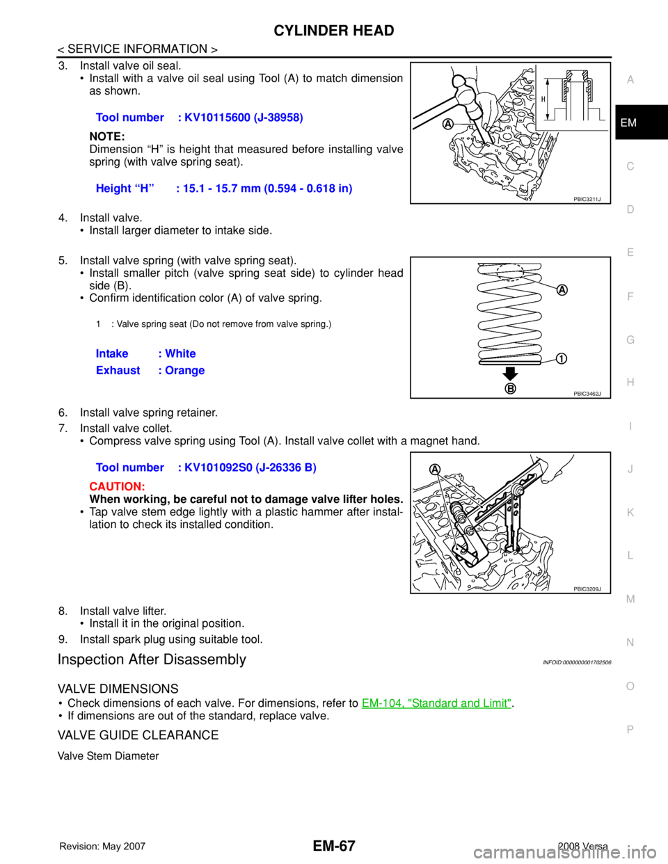
3. Install valve oil seal.
• Install with a valve oil seal using Tool (A) to match dimension
as shown.
NOTE:
Dimension “H” is height that measured before installing valve
spring (with valve spring seat).
4. Install valve.
• Install larger diameter to intake side.
5. Install valve spring (with valve spring seat).
• Install smaller pitch (valve spring seat side) to cylinder head
side (B).
• Confirm identification color (A) of valve spring.
6. Install valve spring retainer.
7. Install valve collet.
• Compress valve spring using Tool (A). Install valve collet with a magnet hand.
CAUTION:
When working, be careful not to damage valve lifter holes.
• Tap valve stem edge lightly with a plastic hammer after instal-
lation to check its installed condition.
8. Install valve lifter.
• Install it in the original position.
9. Install spark plug using suitable tool.
Inspection After DisassemblyINFOID:0000000001702506
VALVE DIMENSIONS
• Check dimensions of each valve. For dimensions, refer to EM-104, "Standard and Limit".
• If dimensions are out of the standard, replace valve.
VALVE GUIDE CLEARANCE
Valve Stem Diameter
Tool number : KV10115600 (J-38958)
Height “H” : 15.1 - 15.7 mm (0.594 - 0.618 in)
PBIC3211J
1 : Valve spring seat (Do not remove from valve spring.)
Intake : White
Exhaust : Orange
PBIC3462J
Tool number : KV101092S0 (J-26336 B)
PBIC3209J