NISSAN LATIO 2009 Service Owners Manual
LATIO 2009
NISSAN
NISSAN
https://www.carmanualsonline.info/img/5/57359/w960_57359-0.png
NISSAN LATIO 2009 Service Owners Manual
Trending: fuel, fuse box, jump start terminals, temp gauge, TPMS, OBD port, alarm
Page 91 of 4331
.
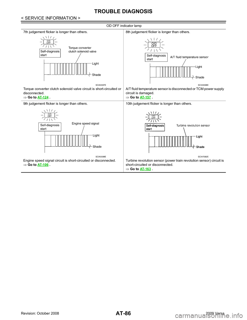
8th judgement flicker is longer than others.
A/T fluid temperature sensor is disconnected or TCM power supply
circuit is damaged.
⇒ Go to AT-157 .
9th judgement flicker is longer than others.
Engine speed signal circuit is short-circuited or disconnected.
⇒ Go to AT-106 .
10th judgement flicker is longer than others.
Turbine revolution sensor (power train revolution sensor) circuit is
short-circuited or disconnected.
⇒ Go to AT-163 .
OD OFF indicator lamp
Page 92 of 4331
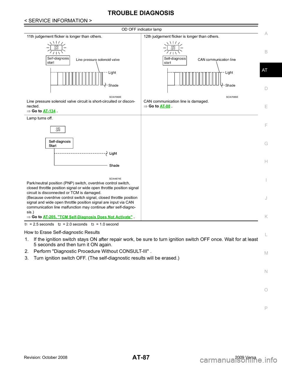
AT
N
O P
t
1 = 2.5 seconds t 2 = 2.0 seconds t 3 = 1.0 second
How to Erase Self-diagnostic Results 1. If the ignition switch stays ON after repair work, be su re to turn ignition switch OFF once. Wait for at least
5 seconds and then turn it ON again.
2. Perform "Diagnostic Procedure Without CONSULT-III" .
3. Turn ignition switch OFF. (The self-diagnostic results will be erased.) 11th judgement flicker is longer than others.
Line pressure solenoid valve circuit is short-circuited or discon-
nected.
⇒ Go to AT-134 .
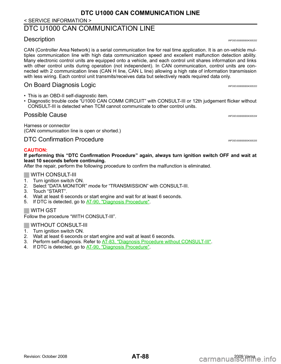
12th judgement flicker is longer than others.
CAN communication line is damaged.
⇒ Go to AT-88 .
Lamp turns off.
Park/neutral position (PNP) switch, overdrive control switch,
closed throttle position signal or wide open throttle position signal
circuit is disconnected or TCM is damaged.
(Because overdrive control switch signal, closed throttle position
signal and wide open throttle position signal are input via CAN
communication line malfunction may continue after self-diagno-
sis.)
⇒ Go to AT-205, " TCM Self-Diagnosis
Does Not Activate " .
OD OFF indicator lamp
Page 93 of 4331
Diagnosis Procedure " .
WITH GST
Follow the procedure “WITH CONSULT-III”.
WITHOUT CONSULT-III
1. Turn ignition switch ON.
2. Wait at least 6 seconds or start engine and wait at least 6 seconds.
3. Perform self-diagnosis. Refer to AT-83, " Diagnosis Procedure without CONSULT-III " .
4. If DTC is detected, go to AT-90, " Diagnosis Procedure " .
Page 94 of 4331
AT
N
O P
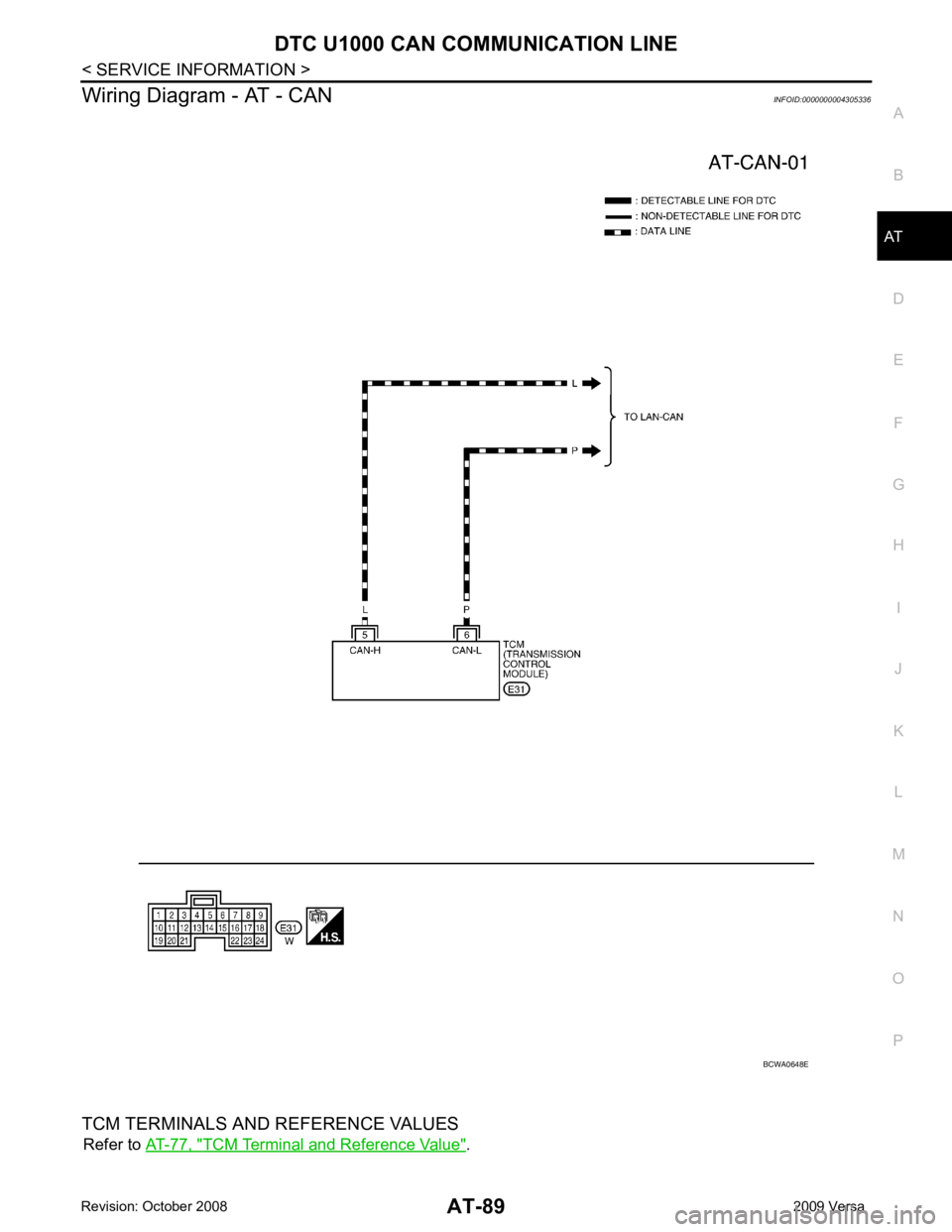
Wiring Diagram - AT - CAN
INFOID:0000000004305336
TCM TERMINALS AND REFERENCE VALUES Refer to AT-77, " TCM Terminal and Reference Value " .
Page 95 of 4331
“ U1000 CAN COMM CIRCUIT ” indicated?
YES >> Print out CONSULT-III screen, Go to LAN section. Refer to
LAN-26, " CAN System Specification
Chart " .
NO >> INSPECTION END
Page 96 of 4331
AT
N
O P
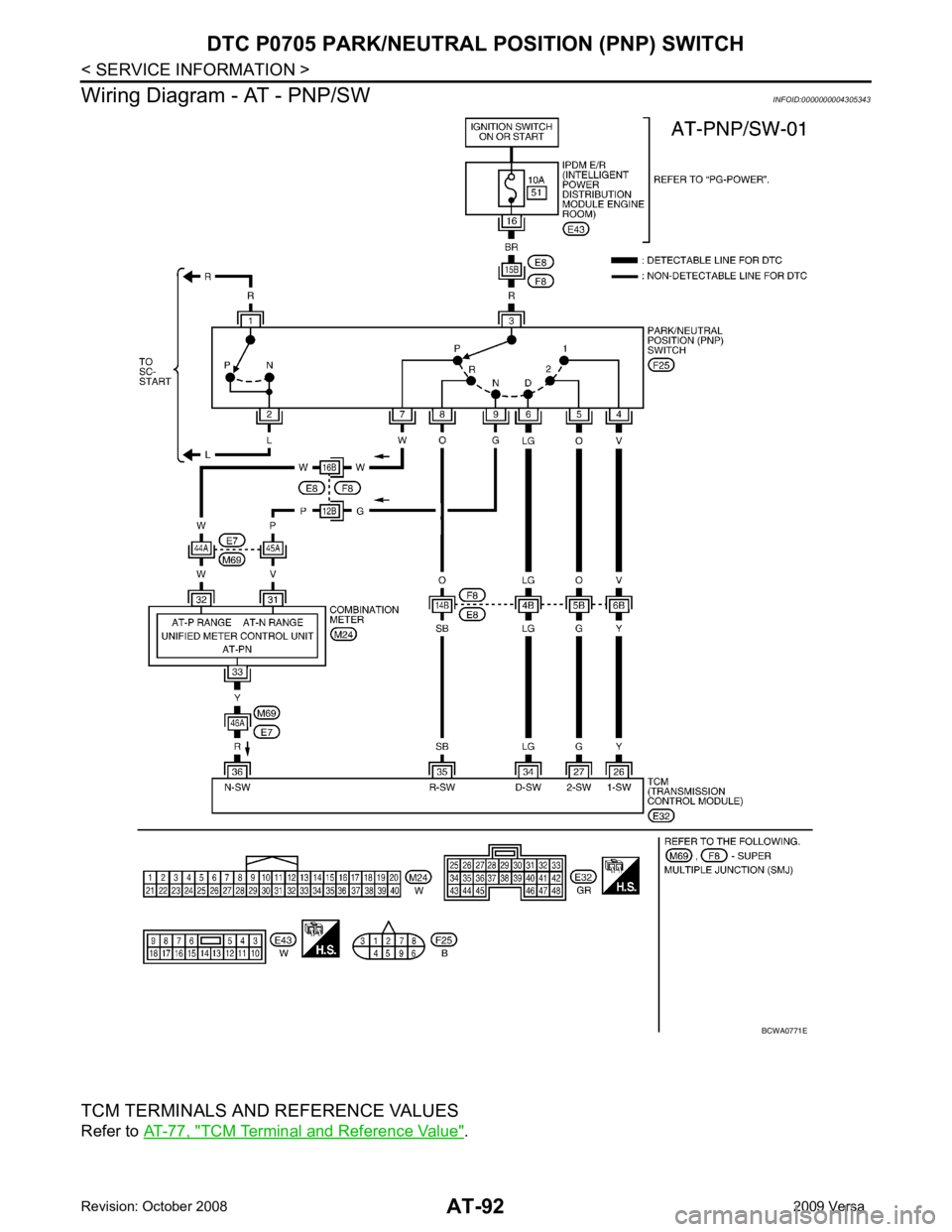
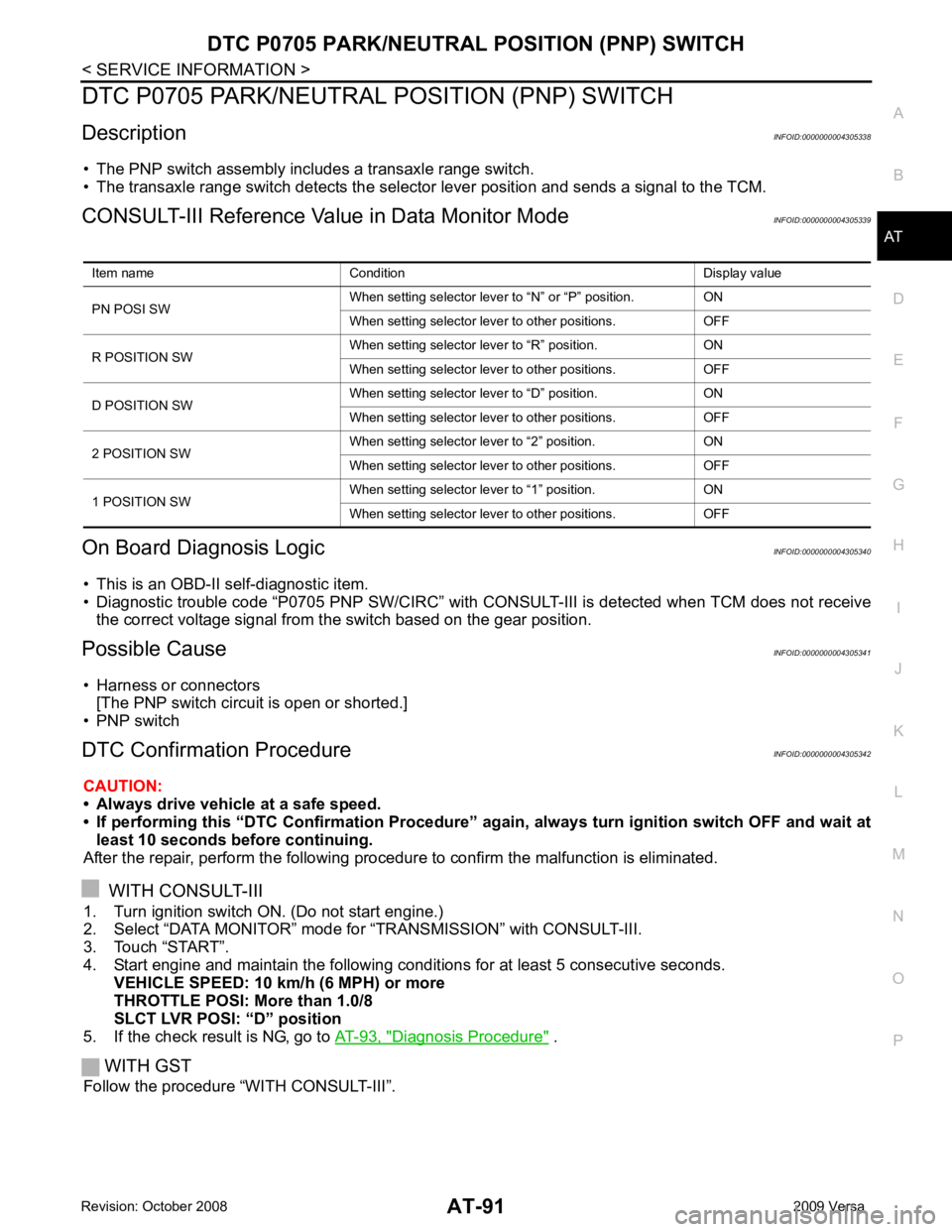
DTC P0705 PARK/NEUTRAL POSITION (PNP) SWITCH
Description INFOID:0000000004305338
• The PNP switch assembly includes a transaxle range switch.
• The transaxle range switch detects the selector lever position and sends a signal to the TCM.
CONSULT-III Reference Val ue in Data Monitor Mode INFOID:0000000004305339
On Board Diagnosis Logic INFOID:0000000004305340
• This is an OBD-II self-diagnostic item.
• Diagnostic trouble code “P0705 PNP SW/CIRC” with CONS ULT-III is detected when TCM does not receive
the correct voltage signal from the switch based on the gear position.
Possible Cause INFOID:0000000004305341
• Harness or connectors [The PNP switch circuit is open or shorted.]
• PNP switch
DTC Confirmation Procedure INFOID:0000000004305342
CAUTION:
• Always drive vehicle at a safe speed.
• If performing this “DTC Confirmation Procedure” again, always turn ignition switch OFF and wait at
least 10 seconds before continuing.
After the repair, perform the following procedure to confirm the malfunction is eliminated.
WITH CONSULT-III
1. Turn ignition switch ON. (Do not start engine.)
2. Select “DATA MONITOR” mode for “TRANSMISSION” with CONSULT-III.
3. Touch “START”.
4. Start engine and maintain the following conditions for at least 5 consecutive seconds.
VEHICLE SPEED: 10 km/h (6 MPH) or more
THROTTLE POSI: More than 1.0/8
SLCT LVR POSI: “D” position
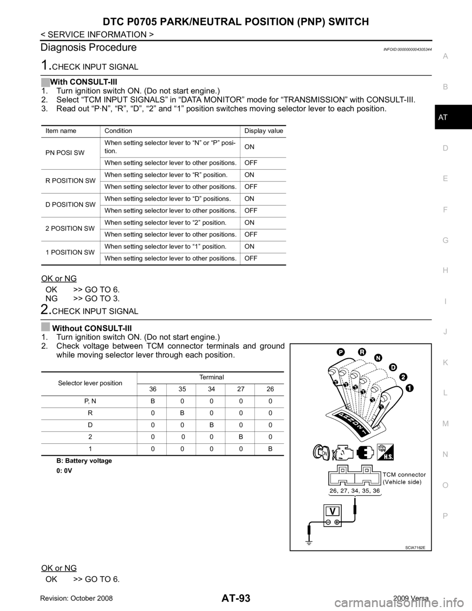
5. If the check result is NG, go to AT-93, " Diagnosis Procedure " .
WITH GST
Follow the procedure “WITH CONSULT-III”. Item name Condition Display value
PN POSI SW When setting selector lever
to “N” or “P” position. ON
When setting selector lever to other positions. OFF
R POSITION SW When setting selector lever to “R” position. ON
When setting selector lever to other positions. OFF
D POSITION SW When setting selector lever to “D” position. ON
When setting selector lever to other positions. OFF
2 POSITION SW When setting selector lever to “2” position. ON
When setting selector lever to other positions. OFF
1 POSITION SW When setting selector lever to “1” position. ON
When setting selector lever to other positions. OFF
Page 97 of 4331
TCM Terminal and Reference Value " .
Page 98 of 4331
AT
N
O P
Diagnosis Procedure
INFOID:0000000004305344OK >> GO TO 6.
NG >> GO TO 3. OK >> GO TO 6.
Item name Condition Display value
PN POSI SW When setting selector le
ver to “N” or “P” posi-
tion. ON
When setting selector lever to other positions. OFF
R POSITION SW When setting selector lever to “R” position. ON
When setting selector lever to other positions. OFF
D POSITION SW When setting selector lever to “D” positions. ON
When setting selector lever to other positions. OFF
2 POSITION SW When setting selector lever to “2” position. ON
When setting selector lever to other positions. OFF
1 POSITION SW When setting selector lever to “1” position. ON
When setting selector lever to other positions. OFF Selector lever position
Terminal
36 35 34 27 26
P, N B 0 0 0 0 R 0 B 0 0 0
D 0 0 B 0 0 2 0 0 0 B 0
1 0 0 0 0 B
Page 99 of 4331
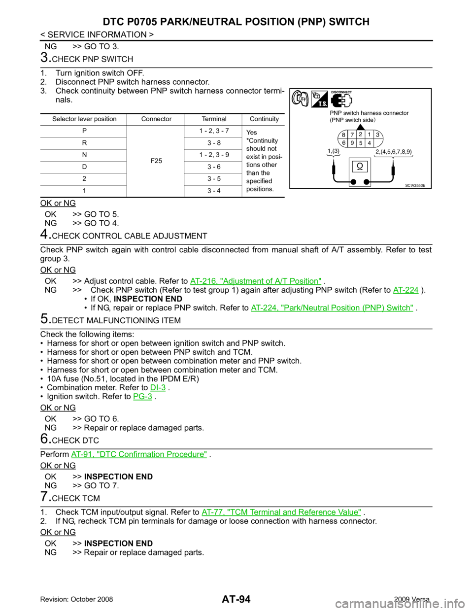
OK >> GO TO 5.
NG >> GO TO 4. OK >> Adjust control cable. Refer to
AT-216, " Adjustment of A/T Position " .
NG >> Check PNP switch (Refer to test group 1) again after adjusting PNP switch (Refer to AT-224 ).
• If OK, INSPECTION END
• If NG, repair or replace PNP switch. Refer to AT-224, " Park/Neutral Position (PNP) Switch " .
.
• Ignition switch. Refer to PG-3 .
OK or NG OK >> GO TO 6.
NG >> Repair or replace damaged parts. DTC Confirmation Procedure " .
OK or NG OK >>
INSPECTION END
NG >> GO TO 7. TCM Terminal and Reference Value " .
2. If NG, recheck TCM pin terminals for damage or loose connection with harness connector.
OK or NG OK >>
INSPECTION END
NG >> Repair or replace damaged parts. Selector lever position Connector Terminal Continuity
P
F251 - 2, 3 - 7
Yes
*Continuity
should not
exist in posi-
tions other
than the
specified
positions.
R 3 - 8
N 1 - 2, 3 - 9
D 3 - 6 2 3 - 5
1 3 - 4
Page 100 of 4331
AT
N
O P
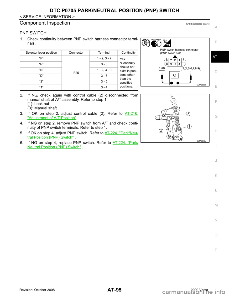
Component Inspection
INFOID:0000000004305345
PNP SWITCH 1. Check continuity between PNP switch harness connector termi- nals.
2. If NG, check again with control cable (2) disconnected from manual shaft of A/T assembly. Refer to step 1.
(1): Lock nut
(3): Manual shaft
3. If OK on step 2, adjust control cable (2). Refer to AT-216," Adjustment of A/T Position " .
4. If NG on step 2, remove PNP switch from A/T and check conti-
nuity of PNP switch terminals. Refer to step 1.
5. If OK on step 4, adjust PNP switch. Refer to AT-224, " Park/Neu-
tral Position (PNP) Switch " .
6. If NG on step 4, replace PNP switch. Refer to AT-224, " Park/
Neutral Position (PNP) Switch " .
Selector lever position Connector Terminal Continuity
“P”
F251 - 2, 3 - 7
Yes
*Continuity
should not
exist in posi-
tions other
than the
specified
positions.
“R” 3 - 8
“N” 1 - 2, 3 - 9
“D” 3 - 6 “2” 3 - 5
“1” 3 - 4
Trending: tow, warning lights, run flat, heating, steering, spark plugs, checking oil
