parking brake NISSAN LATIO 2009 Service Repair Manual
[x] Cancel search | Manufacturer: NISSAN, Model Year: 2009, Model line: LATIO, Model: NISSAN LATIO 2009Pages: 4331, PDF Size: 58.04 MB
Page 22 of 4331
AT
N
O P
A/T FLUID
Checking A/T Fluid INFOID:0000000004305295
1. Warm up engine.
2. Check for A/T fluid leakage.
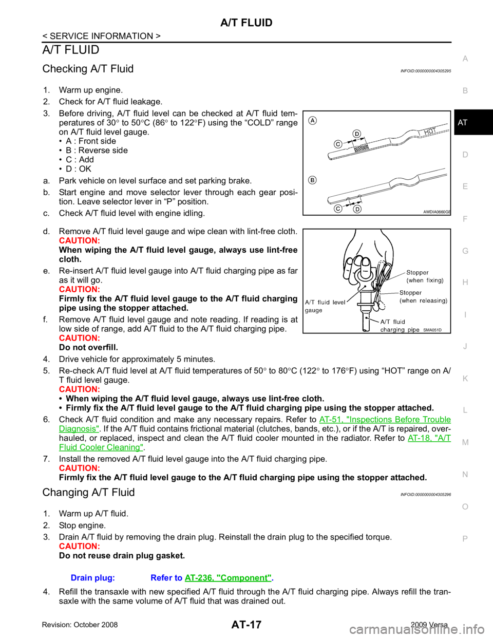
3. Before driving, A/T fluid level can be checked at A/T fluid tem- peratures of 30 ° to 50 °C (86 ° to 122 °F) using the “COLD” range
on A/T fluid level gauge.
• A : Front side
• B : Reverse side
• C : Add
• D : OK
a. Park vehicle on level surface and set parking brake.
b. Start engine and move selector lever through each gear posi- tion. Leave selector lever in “P” position.
c. Check A/T fluid level with engine idling.
d. Remove A/T fluid level gauge and wipe clean with lint-free cloth. CAUTION:
When wiping the A/T fluid l evel gauge, always use lint-free
cloth.
e. Re-insert A/T fluid level gauge into A/T fluid charging pipe as far as it will go.
CAUTION:
Firmly fix the A/T fluid level ga uge to the A/T fluid charging
pipe using the stopper attached.
f. Remove A/T fluid level gauge and note reading. If reading is at low side of range, add A/T fluid to the A/T fluid charging pipe.
CAUTION:
Do not overfill.
4. Drive vehicle for approximately 5 minutes.
5. Re-check A/T fluid level at A/T fluid temperatures of 50° to 80 °C (122 ° to 176 °F) using “HOT” range on A/
T fluid level gauge.
CAUTION:
• When wiping the A/T fluid level gauge, always use lint-free cloth.
• Firmly fix the A/T fluid level ga uge to the A/T fluid charging pipe using the stopper attached.
6. Check A/T fluid condition and make any necessary repairs. Refer to AT-51, " Inspections Before Trouble
Diagnosis " . If the A/T fluid contains frictional material (clu
tches, bands, etc.), or if the A/T is repaired, over-
hauled, or replaced, inspect and clean the A/T fluid cooler mounted in the radiator. Refer to AT-18, " A/T
Fluid Cooler Cleaning " .
7. Install the removed A/T fluid level gauge into the A/T fluid charging pipe. CAUTION:
Firmly fix the A/T fluid level gaug e to the A/T fluid charging pipe using the stopper attached.
Changing A/T Fluid INFOID:0000000004305296
1. Warm up A/T fluid.
2. Stop engine.
3. Drain A/T fluid by removing the drain plug. Re install the drain plug to the specified torque.
CAUTION:
Do not reuse drain plug gasket.
4. Refill the transaxle with new specified A/T fluid th rough the A/T fluid charging pipe. Always refill the tran-
saxle with the same volume of A/T fluid that was drained out. B
Component " .
Page 28 of 4331
AT
N
O P
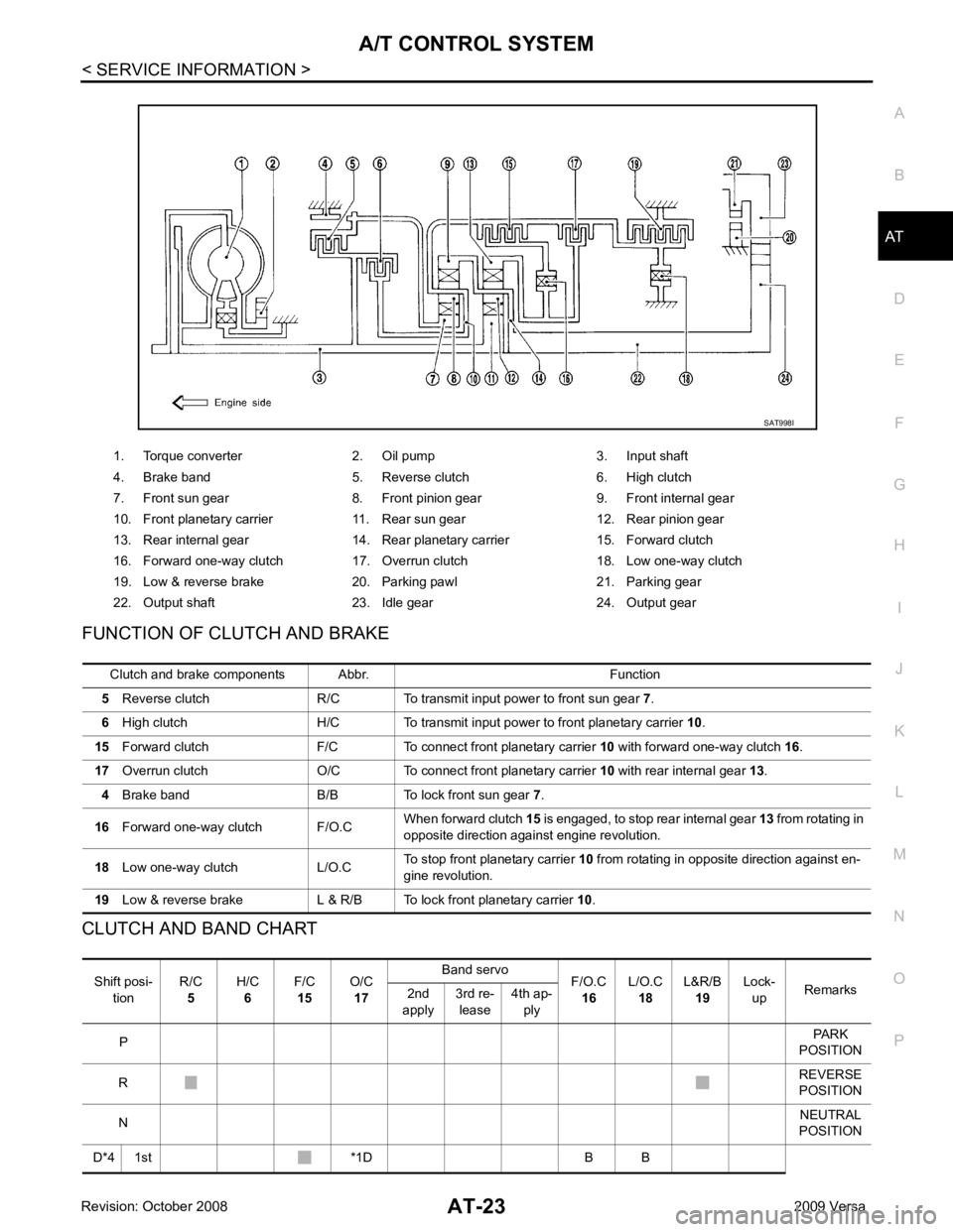
FUNCTION OF CLUTCH AND BRAKE
CLUTCH AND BAND CHART 1. Torque converter 2. Oil pump 3. Input shaft
4. Brake band 5. Reverse clutch 6. High clutch
7. Front sun gear 8. Front pinion gear 9. Front internal gear
10. Front planetary carrier 11. Rear sun gear 12. Rear pinion gear
13. Rear internal gear 14. Rear planetary carrier 15. Forward clutch
16. Forward one-way clutch 17. Overrun clutch 18. Low one-way clutch
19. Low & reverse brake 20. Parking pawl 21. Parking gear
22. Output shaft 23. Idle gear 24. Output gear Shift posi-
tion R/C
5 H/C
6 F/C
15 O/C
17 Band servo
F/O.C
16 L/O.C
18 L&R/B
19 Lock-
up Remarks
2nd
apply 3rd re-
lease 4th ap-
ply
P PARK
POSITION
R REVERSE
POSITION
N NEUTRAL
POSITION
D*4 1st *1D B B
Page 56 of 4331
AT
N
O P
Inspections Before Trouble Diagnosis
INFOID:0000000004305319
A/T FLUID CHECK
Fluid Leakage and Fluid Level Check Check fluid leakage and check the fluid level. Refer to AT-17, " Checking A/T Fluid " .
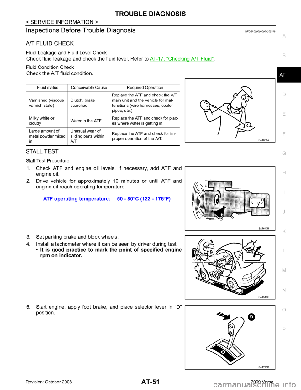
Fluid Condition Check Check the A/T fluid condition.
STALL TEST
Stall Test Procedure 1. Check ATF and engine oil levels. If necessary, add ATF and engine oil.
2. Drive vehicle for approximately 10 minutes or until ATF and engine oil reach operating temperature.
3. Set parking brake and block wheels.
4. Install a tachometer where it can be seen by driver during test. •It is good practice to mark the point of specified engine
rpm on indicator.
5. Start engine, apply foot brake, and place selector lever in “D” position.Fluid status Conceivable Cause Required Operation
Varnished (viscous
varnish state) Clutch, brake
scorched Replace the ATF and check the A/T
main unit and the vehicle for mal-
functions (wire harnesses, cooler
pipes, etc.)
Milky white or
cloudy Water in the ATFReplace the ATF and check for plac-
es where water is getting in.
Large amount of
metal powder mixed
in Unusual wear of
sliding parts within
A/T Replace the ATF and check for im-
proper operation of the A/T. SAT775B
Page 59 of 4331
AT-54< SERVICE INFORMATION >
TROUBLE DIAGNOSIS
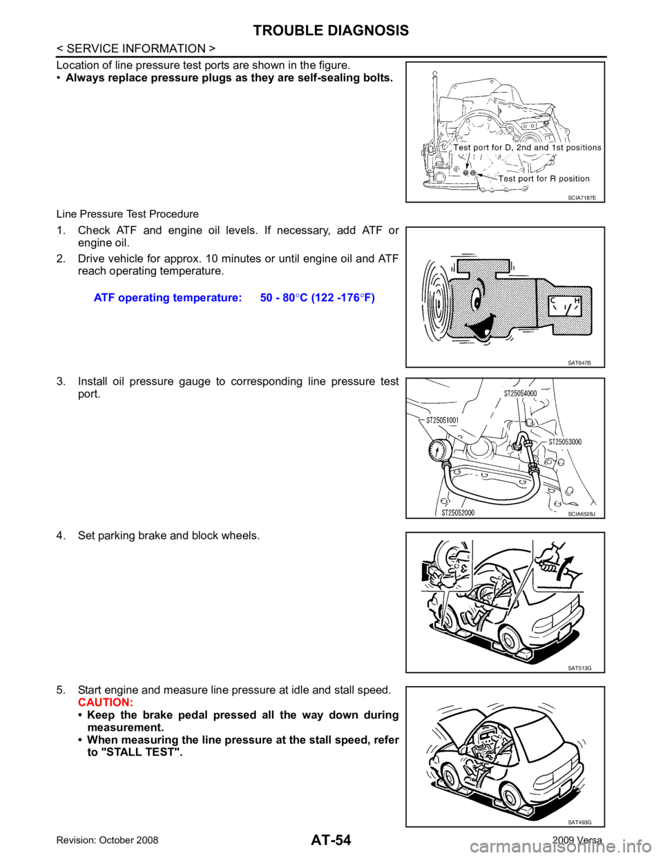
Location of line pressure test ports are shown in the figure.
• Always replace pressure plugs as they are self-sealing bolts.
Line Pressure Test Procedure
1. Check ATF and engine oil levels. If necessary, add ATF or engine oil.
2. Drive vehicle for approx. 10 minutes or until engine oil and ATF reach operating temperature.
3. Install oil pressure gauge to corresponding line pressure test port.
4. Set parking brake and block wheels.
5. Start engine and measure line pressure at idle and stall speed. CAUTION:
• Keep the brake pedal pressed all the way down during
measurement.
• When measuring the line pressure at the stall speed, refer to "STALL TEST". SCIA7187E
ATF operating temperature: 50 - 80
°C (122 -176 °F) SAT647B
SCIA6528J
SAT513G
SAT493G
Page 78 of 4331
AT
N
O P
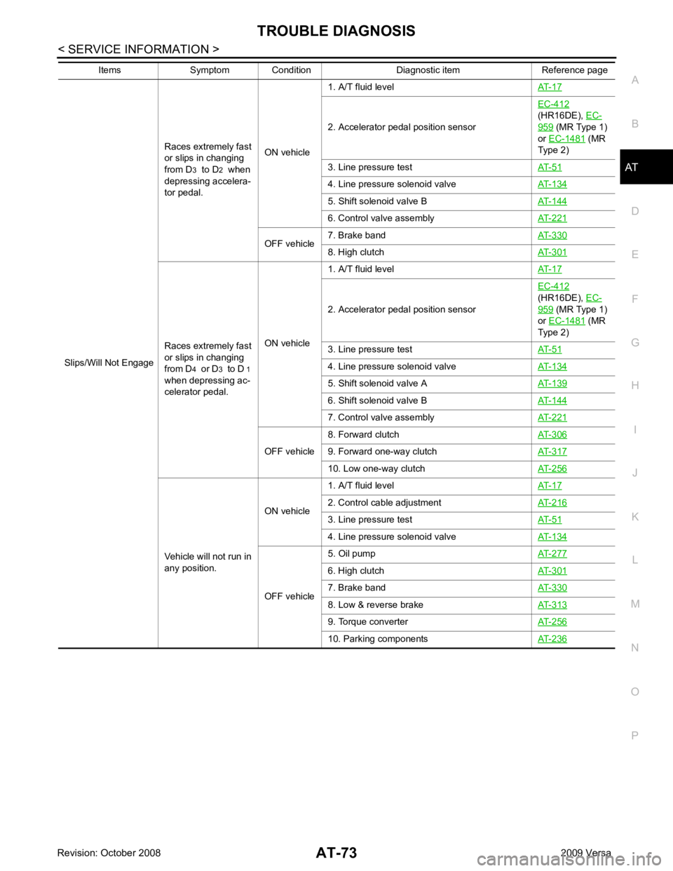
Slips/Will Not Engage
Races extremely fast
or slips in changing
from D 3 to D 2 when
depressing accelera-
tor pedal. ON vehicle1. A/T fluid level
AT-17 2. Accelerator pedal position sensor
EC-412
(HR16DE), EC- 959 (MR Type 1)
or EC-1481 (MR
Type 2)
3. Line pressure test AT-51 4. Line pressure solenoid valve
AT-134 5. Shift solenoid valve B
AT-144 6. Control valve assembly
AT-221 OFF vehicle
7. Brake band
AT-330 8. High clutch
AT-301Races extremely fast
or slips in changing
from D 4 or D 3 to D 1
when depressing ac-
celerator pedal. ON vehicle1. A/T fluid level
AT-17 2. Accelerator pedal position sensor
EC-412
(HR16DE), EC- 959 (MR Type 1)
or EC-1481 (MR
Type 2)
3. Line pressure test AT-51 4. Line pressure solenoid valve
AT-134 5. Shift solenoid valve A
AT-139 6. Shift solenoid valve B
AT-144 7. Control valve assembly
AT-221 OFF vehicle
8. Forward clutch
AT-306 9. Forward one-way clutch
AT-317 10. Low one-way clutch
AT-256Vehicle will not run in
any position. ON vehicle
1. A/T fluid level
AT-17 2. Control cable adjustment
AT-216 3. Line pressure test
AT-51 4. Line pressure solenoid valve
AT-134 OFF vehicle
5. Oil pump
AT-277 6. High clutch
AT-301 7. Brake band
AT-330 8. Low & reverse brake
AT-313 9. Torque converter
AT-256 10. Parking components
AT-236Items Symptom Condition Diagnostic item Reference page
Page 80 of 4331
AT
N
O P
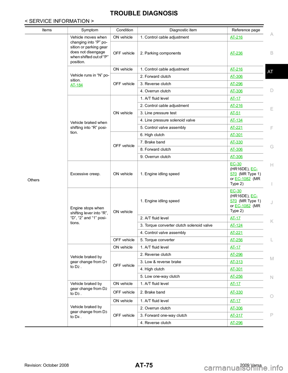
Others Vehicle moves when
changing into “P” po-
sition or parking gear
does not disengage
when shifted out of “P”
position. ON vehicle 1. Control cable adjustment
AT-216OFF vehicle 2. Parking components
AT-236Vehicle runs in “N” po-
sition.
AT-184 ON vehicle 1. Control cable adjustment
AT-216OFF vehicle
2. Forward clutch
AT-306 3. Reverse clutch
AT-296 4. Overrun clutch
AT-306Vehicle braked when
shifting into “R” posi-
tion. ON vehicle
1. A/T fluid level
AT-17 2. Control cable adjustment
AT-216 3. Line pressure test
AT-51 4. Line pressure solenoid valve
AT-134 5. Control valve assembly
AT-221 OFF vehicle
6. High clutch
AT-301 7. Brake band
AT-330 8. Forward clutch
AT-306 9. Overrun clutch
AT-306Excessive creep. ON vehicle 1. Engine idling speed
EC-30
(HR16DE), EC- 570 (MR Type 1)
or EC-1082 (MR
Type 2)
Engine stops when
shifting lever into “R”,
“D”, “2” and “1” posi-
tions. ON vehicle
1. Engine idling speed
EC-30
(HR16DE), EC- 570 (MR Type 1)
or EC-1082 (MR
Type 2)
2. A/T fluid level AT-17 3. Torque converter clutch solenoid valve
AT-124 4. Control valve assembly
AT-221 OFF vehicle 5. Torque converter
AT-256Vehicle braked by
gear change from D 1
to D 2 . ON vehicle 1. A/T fluid level
AT-17OFF vehicle
2. Reverse clutch
AT-296 3. Low & reverse brake
AT-313 4. High clutch
AT-301 5. Low one-way clutch
AT-256Vehicle braked by
gear change from D 2
to D 3 . ON vehicle 1. A/T fluid level
AT-17OFF vehicle 2. Brake band
AT-330Vehicle braked by
gear change from D 3
to D 4 . ON vehicle 1. A/T fluid level
AT-17OFF vehicle
2. Overrun clutch
AT-306 3. Forward one-way clutch
AT-317 4. Reverse clutch
AT-296Items Symptom Condition Diagnostic item Reference page
Page 218 of 4331
AT
N
O P
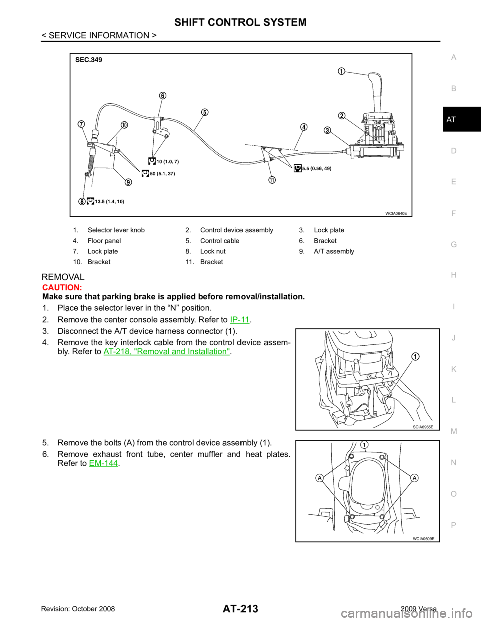
REMOVAL
CAUTION:
Make sure that parking brake is a pplied before removal/installation.
1. Place the selector lever in the “N” position.
2. Remove the center console assembly. Refer to IP-11 .
3. Disconnect the A/T device harness connector (1).
4. Remove the key interlock cabl e from the control device assem-
bly. Refer to AT-218, " Removal and Installation " .
5. Remove the bolts (A) from the control device assembly (1).
6. Remove exhaust front tube, c enter muffler and heat plates.
Refer to EM-144 .
1. Selector lever knob 2. Control device assembly 3. Lock plate
4. Floor panel 5. Control cable 6. Bracket
7. Lock plate 8. Lock nut 9. A/T assembly
10. Bracket 11. Bracket
Page 220 of 4331
AT
N
O P
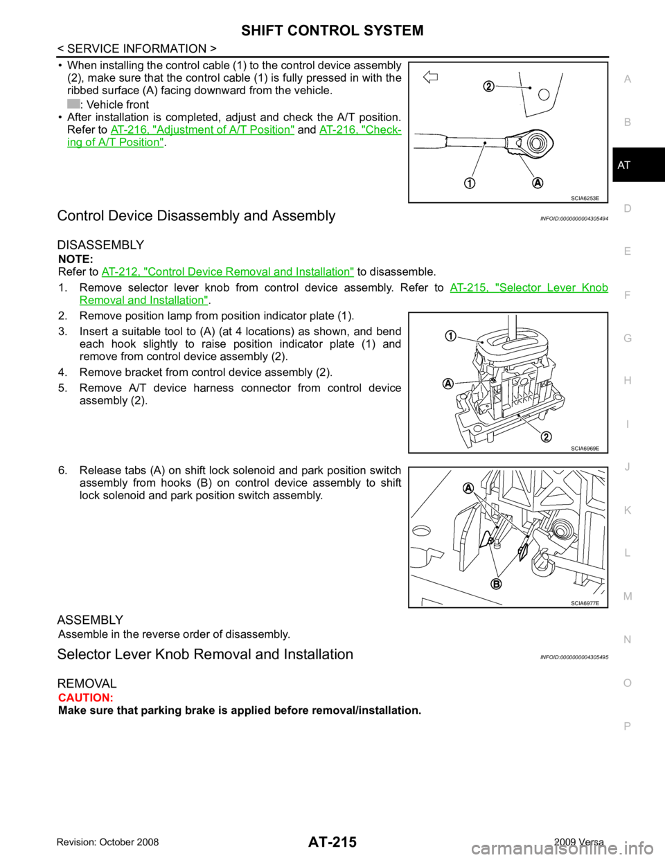
• When installing the control cable (1) to the control device assembly
(2), make sure that the control cable (1) is fully pressed in with the
ribbed surface (A) facing downward from the vehicle.
: Vehicle front
• After installation is completed, adjust and check the A/T position.
Refer to AT-216, " Adjustment of A/T Position " and
AT-216, " Check-
ing of A/T Position " .
Control Device Disassembly and Assembly INFOID:0000000004305494
DISASSEMBLY NOTE:
Refer to AT-212, " Control Device Removal and Installation " to disassemble.
1. Remove selector lever knob from control device assembly. Refer to AT-215, " Selector Lever Knob
Removal and Installation " .
2. Remove position lamp from position indicator plate (1).
3. Insert a suitable tool to (A) (at 4 locations) as shown, and bend each hook slightly to raise position indicator plate (1) and
remove from control device assembly (2).
4. Remove bracket from control device assembly (2).
5. Remove A/T device harness connector from control device assembly (2).
6. Release tabs (A) on shift lock solenoid and park position switch assembly from hooks (B) on control device assembly to shift
lock solenoid and park position switch assembly.
ASSEMBLY Assemble in the reverse order of disassembly.
Selector Lever Knob Re moval and Installation INFOID:0000000004305495
REMOVAL CAUTION:
Make sure that parking brake is a pplied before removal/installation.
Page 809 of 4331
BR
N
O P
BRAKE FLUID
On Board Inspection INFOID:0000000004305892
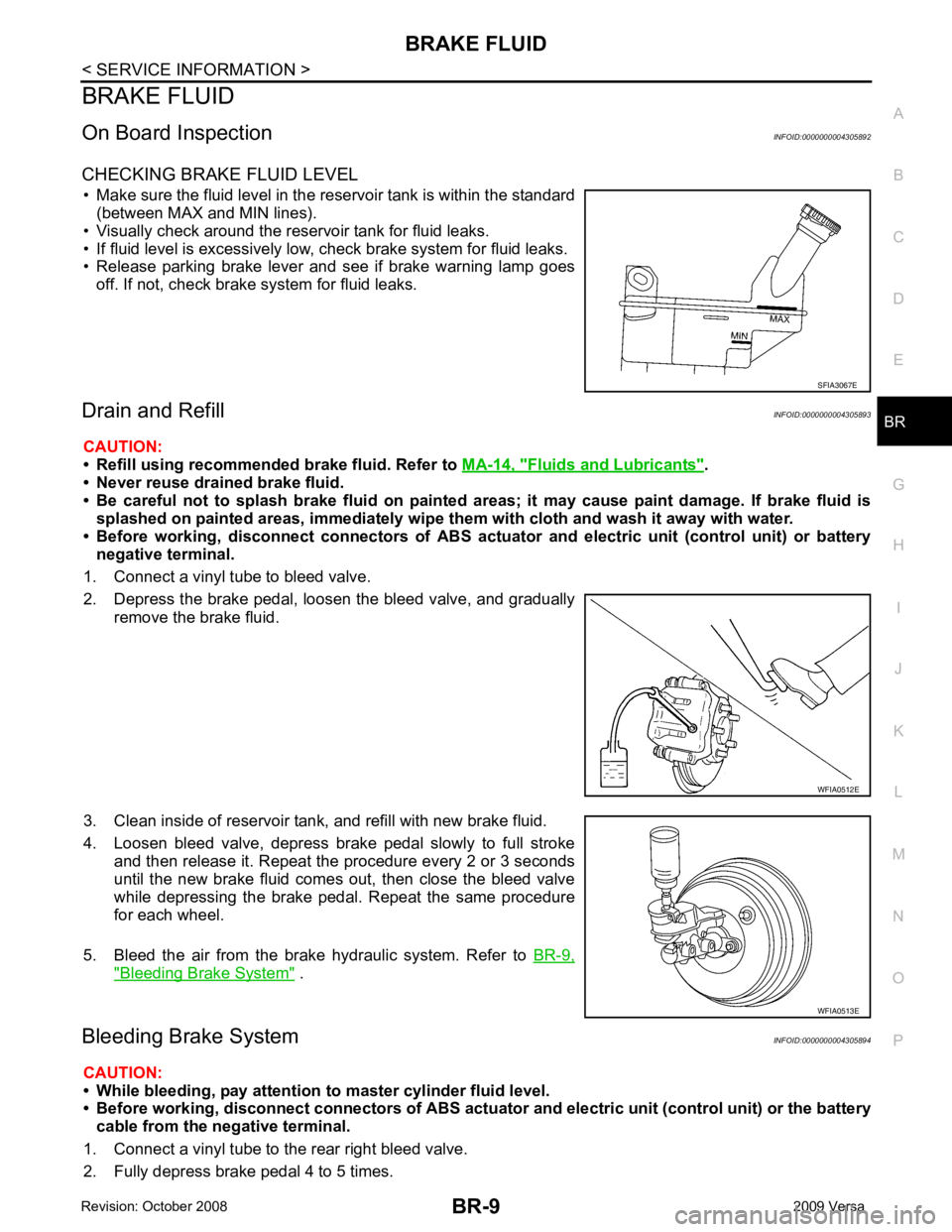
CHECKING BRAKE FLUID LEVEL • Make sure the fluid level in the reservoir tank is within the standard (between MAX and MIN lines).
• Visually check around the reservoir tank for fluid leaks.
• If fluid level is excessively low, check brake system for fluid leaks.
• Release parking brake lever and see if brake warning lamp goes
off. If not, check brake system for fluid leaks.
Drain and Refill INFOID:0000000004305893
CAUTION:
• Refill using recommended brake fluid. Refer to MA-14, " Fluids and Lubricants " .
• Never reuse drained brake fluid.
• Be careful not to splash brake fluid on painted areas; it may cause paint damage. If brake fluid is
splashed on painted areas, immediately wipe th em with cloth and wash it away with water.
• Before working, disconnect connect ors of ABS actuator and electric unit (control unit) or battery
negative terminal.
1. Connect a vinyl tube to bleed valve.
2. Depress the brake pedal, loosen the bleed valve, and gradually remove the brake fluid.
3. Clean inside of reservoir tank, and refill with new brake fluid.
4. Loosen bleed valve, depress brake pedal slowly to full stroke and then release it. Repeat the procedure every 2 or 3 seconds
until the new brake fluid comes out, then close the bleed valve
while depressing the brake pedal . Repeat the same procedure
for each wheel.
5. Bleed the air from the brake hydraulic system. Refer to BR-9," Bleeding Brake System " .
Bleeding Brake System INFOID:0000000004305894
CAUTION:
• While bleeding, pay attention to master cylinder fluid level.
• Before working, disconnect connectors of ABS actuator and electri c unit (control unit) or the battery
cable from the negative terminal.
1. Connect a vinyl tube to the rear right bleed valve.
2. Fully depress brake pedal 4 to 5 times.
Page 835 of 4331
BR
N
O P
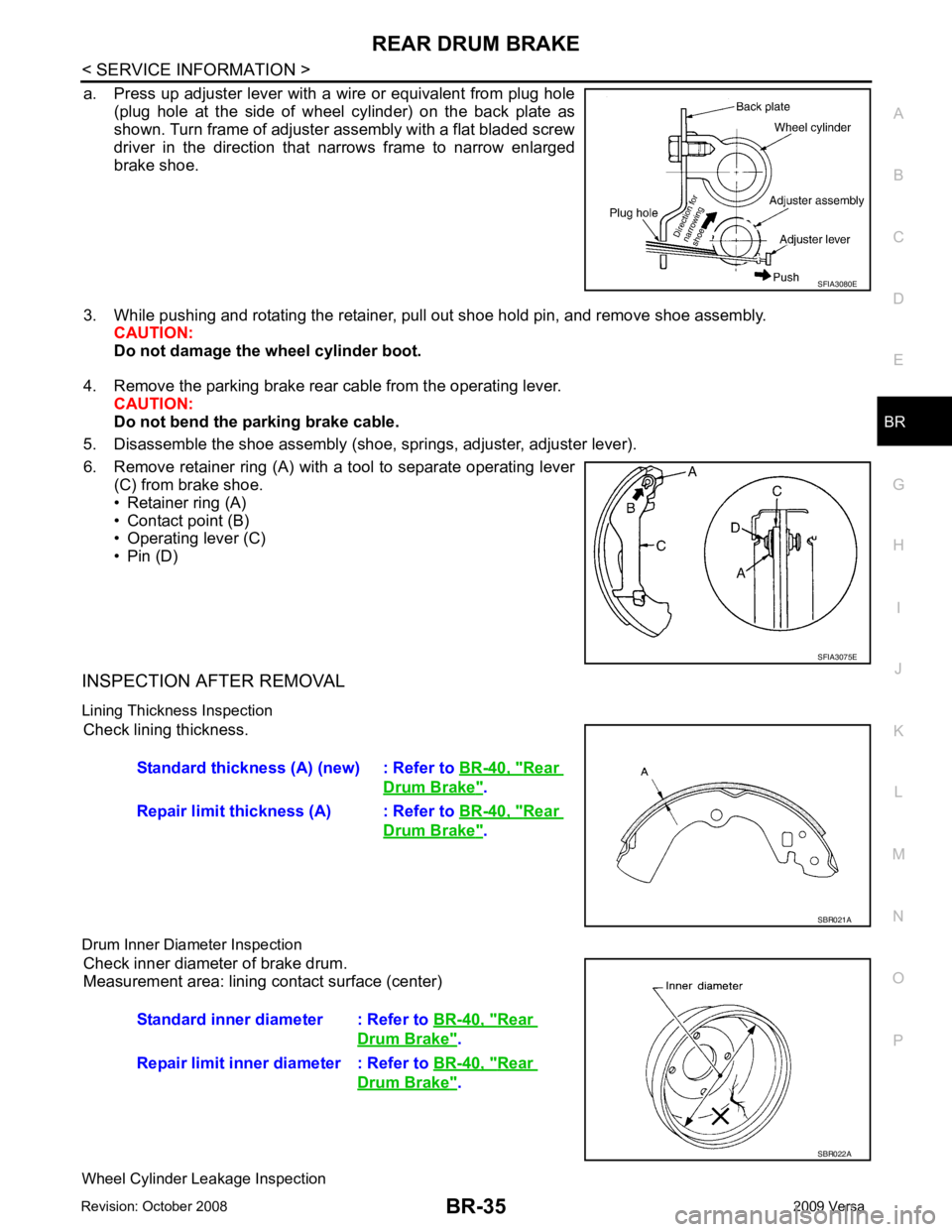
a. Press up adjuster lever with a wire or equivalent from plug hole
(plug hole at the side of wheel cylinder) on the back plate as
shown. Turn frame of adjuster assembly with a flat bladed screw
driver in the direction that narrows frame to narrow enlarged
brake shoe.
3. While pushing and rotating the retainer, pull out shoe hold pin, and remove shoe assembly. CAUTION:
Do not damage the wheel cylinder boot.
4. Remove the parking brake rear cable from the operating lever. CAUTION:
Do not bend the parking brake cable.
5. Disassemble the shoe assembly (shoe, springs, adjuster, adjuster lever).
6. Remove retainer ring (A) with a tool to separate operating lever (C) from brake shoe.
• Retainer ring (A)
• Contact point (B)
• Operating lever (C)
• Pin (D)
INSPECTION AFTER REMOVAL
Lining Thickness Inspection Check lining thickness.
Drum Inner Diameter Inspection Check inner diameter of brake drum.
Measurement area: lining contact surface (center)
Wheel Cylinder Leakage Inspection Rear
Drum Brake " .
Repair limit thickness (A) : Refer to BR-40, " Rear
Drum Brake " .
Rear
Drum Brake " .
Repair limit inner diameter : Refer to BR-40, " Rear
Drum Brake " .