NISSAN LATIO 2009 Service Repair Manual
Manufacturer: NISSAN, Model Year: 2009, Model line: LATIO, Model: NISSAN LATIO 2009Pages: 4331, PDF Size: 58.04 MB
Page 1011 of 4331
CVT
N
O P
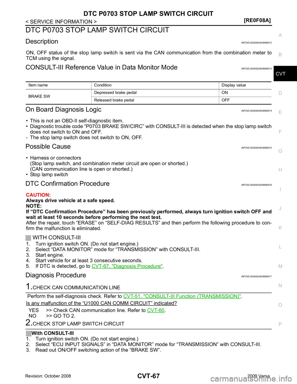
DTC P0703 STOP LAMP SWITCH CIRCUIT
Description INFOID:0000000004666912
ON, OFF status of the stop lamp switch is sent vi a the CAN communication from the combination meter to
TCM using the signal.
CONSULT-III Reference Val ue in Data Monitor Mode INFOID:0000000004666913
On Board Diagnosis Logic INFOID:0000000004666914
• This is not an OBD-II self-diagnostic item.
• Diagnostic trouble code “P0703 BRAKE SW/CIRC” with CO NSULT-III is detected when the stop lamp switch
does not switch to ON and OFF.
- The stop lamp switch does not switch to ON, OFF.
Possible Cause INFOID:0000000004666915
• Harness or connectors (Stop lamp switch, and combination meter circuit are open or shorted.)
(CAN communication line is open or shorted.)
• Stop lamp switch
DTC Confirmation Procedure INFOID:0000000004666916
CAUTION:
Always drive vehicle at a safe speed.
NOTE:
If “DTC Confirmation Procedure” has been previously performed, alw ays turn ignition switch OFF and
wait at least 10 seconds before performing the next test.
After the repair, touch “ERASE” on “SELF-DIAG RESU LTS” and then perform the following procedure to con-
firm the malfunction is eliminated.
WITH CONSULT-III
1. Turn ignition switch ON. (Do not start engine.)
2. Select “DATA MONITOR” mode for “TRANSMISSION” with CONSULT-III.
3. Start engine.
4. Start vehicle for at least 3 consecutive seconds.
5. If DTC is detected, go to CVT-67, " Diagnosis Procedure " .
Diagnosis Procedure INFOID:0000000004666917CONSULT-III Function (TRANSMISSION) " .
Is any malfunction of the “ U1000 CAN COMM CIRCUIT ” indicated?
YES >> Check CAN communication line. Refer to
CVT-60 .
NO >> GO TO 2.
Page 1012 of 4331
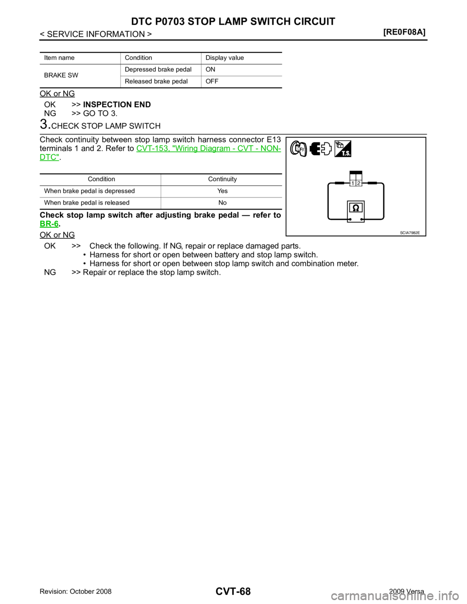
OK >>
INSPECTION END
NG >> GO TO 3. Wiring Diagram - CVT - NON-
DTC " .
Check stop lamp switch after adjusting brake pedal — refer to
BR-6 .
OK or NG OK >> Check the following. If NG, repair or replace damaged parts.
• Harness for short or open between battery and stop lamp switch.
• Harness for short or open between stop lamp switch and combination meter.
NG >> Repair or replace the stop lamp switch.
Item name Condition Display value
BRAKE SW Depressed brake pedal ON
Released brake pedal OFF Condition Continuity
When brake pedal is depressed Yes
When brake pedal is released No
Page 1013 of 4331

CVT
N
O P
DTC P0705 PARK/NEUTRAL POSITION SWITCH
Description INFOID:0000000004666918
• The PNP switch is included in the control valve assembly.
• The PNP switch includes 4 transmission position switches.
• TCM judges the selector lever position by the PNP switch signal.
CONSULT-III Reference Val ue in Data Monitor Mode INFOID:0000000004666919
On Board Diagnosis Logic INFOID:0000000004666920
• This is an OBD-II self-diagnostic item.
• Diagnostic trouble code “P0705 PNP SW/CIRC” with CO NSULT-III is detected under the following condi-
tions.
- When TCM does not receive the correct voltage signal from the PNP switches 1, 2, 3 and 4 based on the gear position.
- When the signal from monitor terminal of PNP switch 3 is different from PNP switch 3.
Possible Cause INFOID:0000000004666921
• Harness or connectors (PNP switches 1, 2, 3, 4 and TCM circuit is open or shorted.)
• PNP switches 1, 2, 3, 4
• PNP switch 3 monitor terminal is open or shorted
DTC Confirmation Procedure INFOID:0000000004666922
CAUTION:
Always drive vehicle at a safe speed.
NOTE:
If “DTC Confirmation Procedure” has been previously performed, alw ays turn ignition switch OFF and
wait at least 10 seconds before performing the next test.
After the repair, touch “ERASE” on “SELF-DIAG RESU LTS” and then perform the following procedure to con-
firm the malfunction is eliminated.
WITH CONSULT-III
Shift position PNP switch 1 PNP switch 2 PNP switch 3 PNP switch 4 PNP switch 3 (monitor)
P OFF OFF OFF OFF OFF
R ON OFF OFF ON OFF
N ON ON OFF OFF OFF
D ON ON ON ON ON L OFF ON ON OFF ON Item name Condition Display value
INH SW3M Selector lever in “D
” and “L” positions ON
Selector lever in “P”, “R” and “N” positions OFF
INH SW4 Selector lever in “R
” and “D” positions ON
Selector lever in “P”, “N” and “L” positions OFF
INH SW3 Selector lever in “D
” and “L” positions ON
Selector lever in “P”, “R” and “N” positions OFF
INH SW2 Selector lever in “N”,
“D” and “L” positions ON
Selector lever in “P ” and “R” positions OFF
INH SW1 Selector lever in “R”,
“N” and “D” positions ON
Selector lever in “P” and “L” positions OFF
Page 1014 of 4331

Diagnosis Procedure " .
WITH GST
Follow the procedure “WITH CONSULT-III”.
Page 1015 of 4331
CVT
N
O P
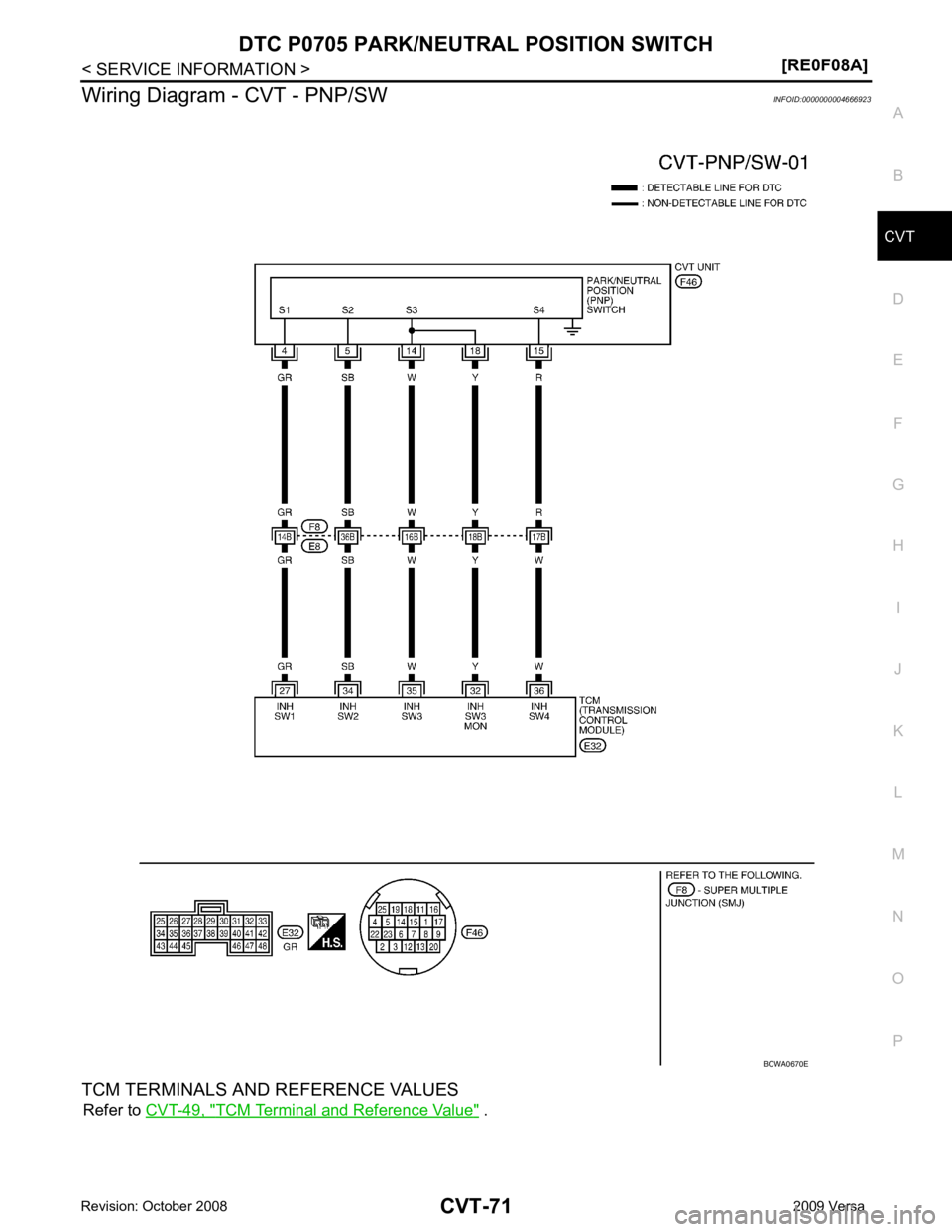
Wiring Diagram - CVT - PNP/SW
INFOID:0000000004666923
TCM TERMINALS AND REFERENCE VALUES Refer to CVT-49, " TCM Terminal and Reference Value " .
Page 1016 of 4331
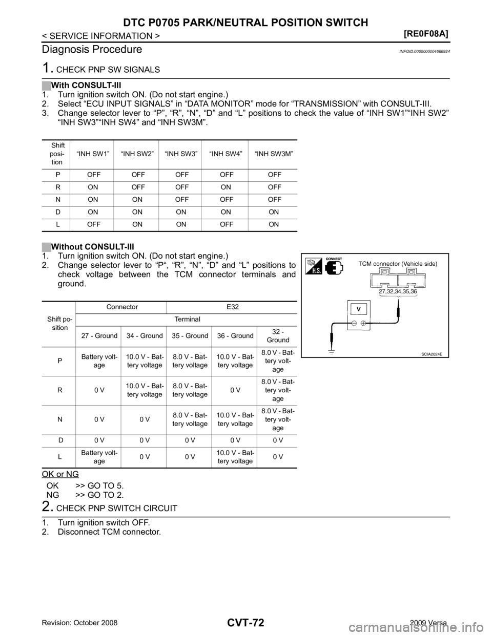
OK >> GO TO 5.
NG >> GO TO 2. Shift po-
sition Connector E32
Terminal
27 - Ground 34 - Ground 35 - Ground 36 - Ground 32 -
Ground
P Battery volt-
age 10.0 V - Bat-
tery voltage 8.0 V - Bat-
tery voltage 10.0 V - Bat-
tery voltage 8.0 V - Bat-
tery volt-
age
R 0 V 10.0 V - Bat-
tery voltage 8.0 V - Bat-
tery voltage 0 V8.0 V - Bat-
tery volt- age
N 0 V 0 V 8.0 V - Bat-
tery voltage 10.0 V - Bat-
tery voltage 8.0 V - Bat-
tery volt- age
D 0 V 0 V 0 V 0 V 0 V
L Battery volt-
age 0 V 0 V 10.0 V - Bat-
tery voltage 0 V
Page 1017 of 4331
CVT
N
O P
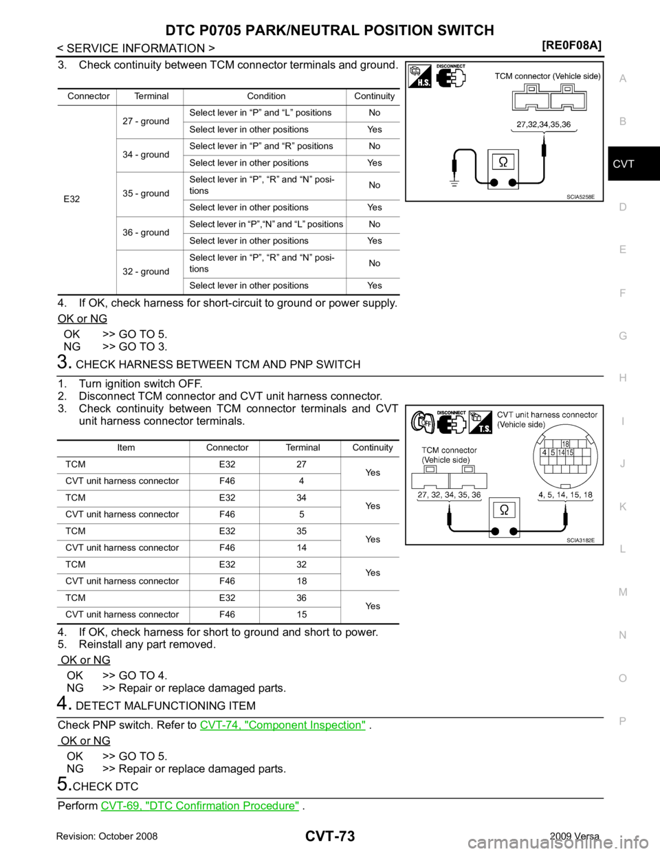
3. Check continuity between TCM connector terminals and ground.
4. If OK, check harness for short-circuit to ground or power supply.
OK or NG OK >> GO TO 5.
NG >> GO TO 3. OK >> GO TO 4.
NG >> Repair or replace damaged parts. Component Inspection " .
OK or NG OK >> GO TO 5.
NG >> Repair or replace damaged parts. DTC Confirmation Procedure " .
Connector Terminal Condition Continuity
E32 27 - ground
Select lever in “P”
and “L” positions No
Select lever in other positions Yes
34 - ground Select lever in “P”
and “R” positions No
Select lever in other positions Yes
35 - ground Select lever in “P”,
“R” and “N” posi-
tions No
Select lever in other positions Yes
36 - ground Select lever in “P”,“N
” and “L” positions No
Select lever in other positions Yes
32 - ground Select lever in “P”,
“R” and “N” posi-
tions No
Select lever in other positions Yes
Page 1018 of 4331
OK >>
INSPECTION END
NG >> GO TO 6. TCM Terminal and Reference Value " .
2. If NG, re-check TCM pin terminals for damage or loose connection with harness connector.
OK or NG OK >>
INSPECTION END
NG >> 1. Repair or replace damaged parts.
2. Replace the transaxle assembly. Refer to CVT-182, " Removal and Installation " .
Component Inspection INFOID:0000000004666925
PNP SWITCH
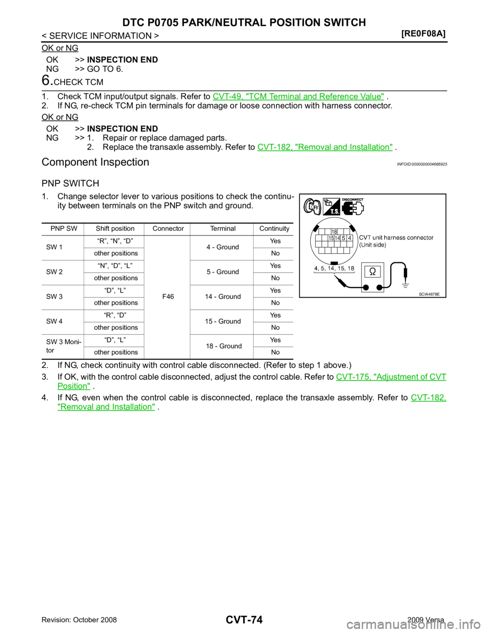
1. Change selector lever to various positions to check the continu- ity between terminals on the PNP switch and ground.
2. If NG, check continuity with control c able disconnected. (Refer to step 1 above.)
3. If OK, with the control cable disconnect ed, adjust the control cable. Refer to CVT-175, " Adjustment of CVT
Position " .
4. If NG, even when the control cable is disconnected, replace the transaxle assembly. Refer to CVT-182," Removal and Installation " .
PNP SW Shift position Connector Terminal Continuity
SW 1 “R”, “N”, “D”
F464 - Ground
Yes
other positions No
SW 2 “N”, “D”, “L”
5 - Ground Yes
other positions No
SW 3 “D”, “L”
14 - Ground Yes
other positions No
SW 4 “R”, “D”
15 - Ground Yes
other positions No
SW 3 Moni-
tor “D”, “L”
18 - Ground Yes
other positions No
Page 1019 of 4331
CVT
N
O P
DTC P0710 CVT FLUID TEMPER
ATURE SENSOR CIRCUIT
Description INFOID:0000000004666926
• The CVT fluid temperature sensor is included in the control valve assembly.
• The CVT fluid temperature sensor detects the CV T fluid temperature and sends a signal to the TCM.
CONSULT-III Reference Val ue in Data Monitor Mode INFOID:0000000004666927
Remarks: Specification data are reference values.
On Board Diagnosis Logic INFOID:0000000004666928
• This is an OBD-II self-diagnostic item.
• Diagnostic trouble code “P0710 ATF TEMP SEN/CIRC” with CONSULT-III is detected when TCM receives
an excessively low or high voltage from the sensor.
Possible Cause INFOID:0000000004666929
• Harness or connectors (Sensor circuit is open or shorted.)
• CVT fluid temperature sensor
DTC Confirmation Procedure INFOID:0000000004666930
CAUTION:
Always drive vehicle at a safe speed.
NOTE:
If “DTC Confirmation Procedure” has been previously performed, alw ays turn ignition switch OFF and
wait at least 10 seconds before performing the next test.
After the repair, touch “ERASE” on “SELF-DIAG RESU LTS” and then perform the following procedure to con-
firm the malfunction is eliminated.
WITH CONSULT-III
1. Turn ignition switch ON. (Do not start engine.)
2. Select “DATA MONITOR” mode for “TRANSMISSION” with CONSULT-III.
3. Start engine and maintain the following conditions for at least 10 minutes (Total). VEHICLE SPEED: 10 km/h (6 MPH) or more
ENG SPEED: 450 rpm more than
ACC PEDAL OPEN: More than 1.0/8
RANGE: “D” position
4. If DTC is detected, go to CVT-77, " Diagnosis Procedure " .
WITH GST
Follow the procedure “WITH CONSULT-III”. Item name Condition Display value (Approx.)
ATF TEMP SEN When CVT fluid temperature is 20
°C (68 °F). 2.0 V
When CVT fluid temperature is 80 °C (176 °F). 1.0 V
Page 1020 of 4331
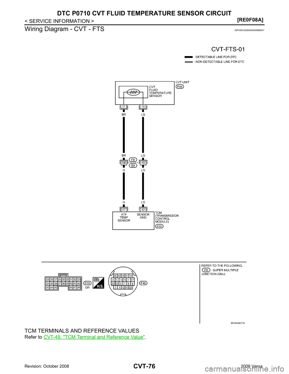
TCM Terminal and Reference Value " .