NISSAN LATIO 2009 Service Repair Manual
Manufacturer: NISSAN, Model Year: 2009, Model line: LATIO, Model: NISSAN LATIO 2009Pages: 4331, PDF Size: 58.04 MB
Page 1191 of 4331
CVT
N
O P
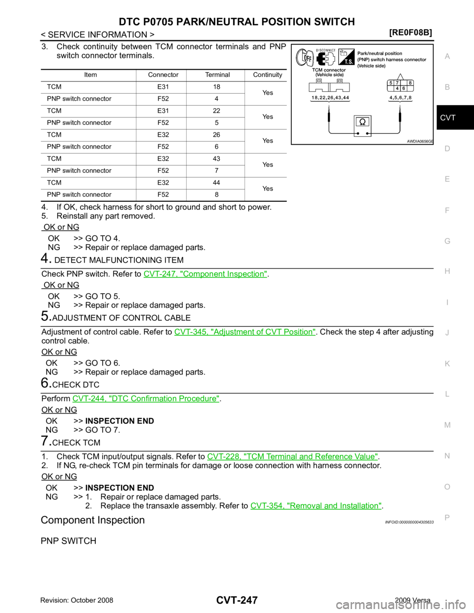
3. Check continuity between TCM connector terminals and PNP
switch connector terminals.
4. If OK, check harness for short to ground and short to power.
5. Reinstall any part removed.
OK or NG OK >> GO TO 4.
NG >> Repair or replace damaged parts. Component Inspection " .
OK or NG OK >> GO TO 5.
NG >> Repair or replace damaged parts. Adjustment of CVT Position " . Check the step 4 after adjusting
control cable.
OK or NG OK >> GO TO 6.
NG >> Repair or replace damaged parts. DTC Confirmation Procedure " .
OK or NG OK >>
INSPECTION END
NG >> GO TO 7. TCM Terminal and Reference Value " .
2. If NG, re-check TCM pin terminals for dam age or loose connection with harness connector.
OK or NG OK >>
INSPECTION END
NG >> 1. Repair or replace damaged parts. 2. Replace the transaxle assembly. Refer to CVT-354, " Removal and Installation " .
Component Inspection INFOID:0000000004305633
PNP SWITCH Item Connector Terminal Continuity
TCM E31 18 Yes
PNP switch connector F52 4
TCM E31 22 Yes
PNP switch connector F52 5
TCM E32 26 Yes
PNP switch connector F52 6
TCM E32 43 Yes
PNP switch connector F52 7
TCM E32 44 Yes
PNP switch connector F52 8 B
Page 1192 of 4331
Adjustment of CVT
Position " .
4. If NG, even when the control cable is disconnected, replace the transaxle assembly. Refer to CVT-354," Removal and Installation " .
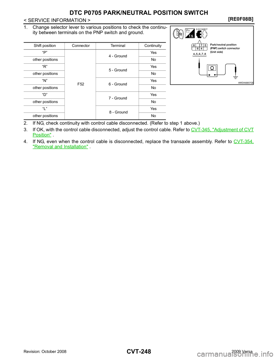
Shift position Connector Terminal Continuity
“P”
F524 - Ground
Yes
other positions No “R” 5 - Ground Yes
other positions No “N” 6 - Ground Yes
other positions No “D” 7 - Ground Yes
other positions No “L” 8 - Ground Yes
other positions No B
Page 1193 of 4331

CVT
N
O P
DTC P0710 CVT FLUID TEMPER
ATURE SENSOR CIRCUIT
Description INFOID:0000000004305634
• The CVT fluid temperature sensor is included in the control valve assembly.
• The CVT fluid temperature sensor detects the CV T fluid temperature and sends a signal to the TCM.
CONSULT-III Reference Val ue in Data Monitor Mode INFOID:0000000004305635
Remarks: Specification data are reference values.
On Board Diagnosis Logic INFOID:0000000004305636
• This is an OBD-II self-diagnostic item.
• Diagnostic trouble code “P0710 ATF TEMP SEN/CIRC” with CONSULT-III is detected when TCM receives
an excessively low or high voltage from the sensor.
Possible Cause INFOID:0000000004305637
• Harness or connectors (Sensor circuit is open or shorted.)
• CVT fluid temperature sensor
DTC Confirmation Procedure INFOID:0000000004305638
CAUTION:
Always drive vehicle at a safe speed.
NOTE:
If “DTC Confirmation Procedure” has been previously performed, alw ays turn ignition switch OFF and
wait at least 10 seconds before performing the next test.
After the repair, touch “ERASE” on “SELF-DIAG RESU LTS” and then perform the following procedure to con-
firm the malfunction is eliminated.
WITH CONSULT-III
1. Turn ignition switch ON. (Do not start engine.)
2. Select “DATA MONITOR” mode for “TRANSMISSION” with CONSULT-III.
3. Start engine and maintain the following conditions for at least 10 minutes (Total). VEHICLE SPEED: 10 km/h (6 MPH) or more
ENG SPEED: 450 rpm more than
ACC PEDAL OPEN: More than 1.0/8
RANGE: “D” position
4. If DTC is detected, go to CVT-251, " Diagnosis Procedure " .
WITH GST
Follow the procedure “WITH CONSULT-III”. Item name Condition Display value (Approx.)
ATF TEMP SEN When CVT fluid temperature is 20
°C (68 °F). 2.0 V
When CVT fluid temperature is 80 °C (176 °F). 1.0 V
Page 1194 of 4331
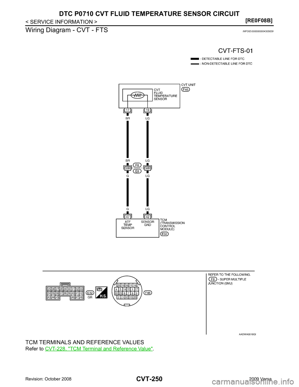
TCM Terminal and Reference Value " . B
Page 1195 of 4331
![NISSAN LATIO 2009 Service Repair Manual DTC P0710 CVT FLUID TEMP
ERATURE SENSOR CIRCUIT
CVT-251
< SERVICE INFORMATION >
[RE0F08B] D
E
F
G H
I
J
K L
M A
B CVT
N
O P
Diagnosis Procedure
INFOID:00000000043056401.
CHECK CVT FLUID TEMP ERATURE NISSAN LATIO 2009 Service Repair Manual DTC P0710 CVT FLUID TEMP
ERATURE SENSOR CIRCUIT
CVT-251
< SERVICE INFORMATION >
[RE0F08B] D
E
F
G H
I
J
K L
M A
B CVT
N
O P
Diagnosis Procedure
INFOID:00000000043056401.
CHECK CVT FLUID TEMP ERATURE](/img/5/57359/w960_57359-1194.png)
DTC P0710 CVT FLUID TEMP
ERATURE SENSOR CIRCUIT
CVT-251
< SERVICE INFORMATION >
[RE0F08B] D
E
F
G H
I
J
K L
M A
B CVT
N
O P
Diagnosis Procedure
INFOID:00000000043056401.
CHECK CVT FLUID TEMP ERATURE SENSOR SIGNAL
With CONSULT-III
1. Start engine.
2. Select “ECU INPUT SIGNALS” in “DATA MONITO R” mode for “TRANSMISSION” with CONSULT-III.
3. Read out the value of “ATF TEMP SEN”.
Without CONSULT-III
1. Start engine.
2. Check voltage between TCM connector terminals.
3. Turn ignition switch OFF.
4. Disconnect TCM connector.
5. Check if there is continuity between connector terminal and
ground.
OK or NG OK >> GO TO 5.
NG >> GO TO 2. 2.
CHECK CVT FLUID TEMP ERATURE SENSOR CIRCUIT
1. Turn ignition switch OFF.
2. Disconnect the TCM connector.
3. Check resistance between TCM connector terminals.
OK or NG OK >> GO TO 5.
NG >> GO TO 3. 3.
CHECK CVT FLUID TEMPERATURE SENSOR
1. Turn ignition switch OFF.
2. Disconnect CVT unit harness connector. Item name Condition
Display value
(Approx.)
ATF TEMP SEN When CVT fluid temperature is 20
°C
(68 °F). 2.0 V
When CVT fluid temperature is 80 °C
(176 °F). 1.0 VName Connector Terminal
Temperature
°C ( °F) Voltage
(Approx.)
CVT fluid tem-
perature sen-
sor E32 47 - 42 20 (68) 2.0 V
80 (176) 1.0 V SCIA2027E
Name Connector Terminal
Temperature
°C ( °F) Resistance
(Approx.)
CVT fluid tem-
perature sensor E32 47 - 42 20 (68) 6.5 k
Ω
80 (176) 0.9 k Ω SCIA2510E
Page 1196 of 4331
![NISSAN LATIO 2009 Service Repair Manual CVT-252< SERVICE INFORMATION >
[RE0F08B]
DTC P0710 CVT FLUID TEMPERATURE SENSOR CIRCUIT
3. Check resistance between CVT unit harness connector termi- nals.
4. Reinstall any part removed.
OK or NISSAN LATIO 2009 Service Repair Manual CVT-252< SERVICE INFORMATION >
[RE0F08B]
DTC P0710 CVT FLUID TEMPERATURE SENSOR CIRCUIT
3. Check resistance between CVT unit harness connector termi- nals.
4. Reinstall any part removed.
OK or](/img/5/57359/w960_57359-1195.png)
CVT-252< SERVICE INFORMATION >
[RE0F08B]
DTC P0710 CVT FLUID TEMPERATURE SENSOR CIRCUIT
3. Check resistance between CVT unit harness connector termi- nals.
4. Reinstall any part removed.
OK or NG OK >> GO TO 4.
NG >> Replace the transaxle assembly. Refer to CVT-354, " Removal and Installation " .
4.
CHECK HARNESS BETWEEN TCM A ND CVT FLUID TEMPERATURE SENSOR
1. Turn ignition switch OFF.
2. Disconnect the TCM connector and CVT unit harness connector.
3. Check continuity between TCM connector terminals and CVT
unit harness connector terminals.
4. If OK, check harness for short to ground and short to power.
5. Reinstall any part removed.
OK or NG OK >> GO TO 5.
NG >> Repair or replace damaged parts. 5.
CHECK DTC
Perform CVT-249, " DTC Confirmation Procedure " .
OK or NG OK >>
INSPECTION END
NG >> GO TO 6. 6.
CHECK TCM
1. Check TCM input/output signals. Refer to CVT-228, " TCM Terminal and Reference Value " .
2. If NG, re-check TCM pin terminals for damage or loose connection with harness connector.
OK or NG OK >>
INSPECTION END
NG >> Repair or replace damaged parts.
Component Inspection INFOID:0000000004305641
CVT FLUID TEMPERATURE SENSOR
1. Turn ignition switch OFF.
2. Disconnect CVT unit harness connector. Name Connector Terminal
Tempera-
ture °C ( °F) Resistance
(Approx.)
CVT fluid
temperature
sensor F46 17 - 19 20 (68) 6.5 k
Ω
80 (176) 0.9 k Ω SCIA4679E
Item Connector Terminal Continuity
TCM E32 42 Yes
CVT unit harness connector F46 19
TCM E32 47 Yes
CVT unit harness connector F46 17 SCIA4680E
Page 1197 of 4331
![NISSAN LATIO 2009 Service Repair Manual DTC P0710 CVT FLUID TEMP
ERATURE SENSOR CIRCUIT
CVT-253
< SERVICE INFORMATION >
[RE0F08B] D
E
F
G H
I
J
K L
M A
B CVT
N
O P
3. Check resistance between CVT unit harness connector termi-
nals.
4 NISSAN LATIO 2009 Service Repair Manual DTC P0710 CVT FLUID TEMP
ERATURE SENSOR CIRCUIT
CVT-253
< SERVICE INFORMATION >
[RE0F08B] D
E
F
G H
I
J
K L
M A
B CVT
N
O P
3. Check resistance between CVT unit harness connector termi-
nals.
4](/img/5/57359/w960_57359-1196.png)
DTC P0710 CVT FLUID TEMP
ERATURE SENSOR CIRCUIT
CVT-253
< SERVICE INFORMATION >
[RE0F08B] D
E
F
G H
I
J
K L
M A
B CVT
N
O P
3. Check resistance between CVT unit harness connector termi-
nals.
4. If NG, replace the transaxle assembly. Refer to CVT-354," Removal and Installation " .
Name Connector Terminal
Tempera-
ture °C ( °F) Resistance
(Approx.)
CVT fluid
temperature
sensor F46 17 - 19 20 (68) 6.5 k
Ω
80 (176) 0.9 k Ω SCIA4679E
Page 1198 of 4331

Diagnosis Procedure " .
WITH GST
Follow the procedure “WITH CONSULT-III”. Item name Condition Display value
ENG SPEED SIG Engine running Closely matches the tachometer reading.
PRI SPEED SEN During driving (lock-up ON) Approximately matches the engine speed.
Page 1199 of 4331
CVT
N
O P
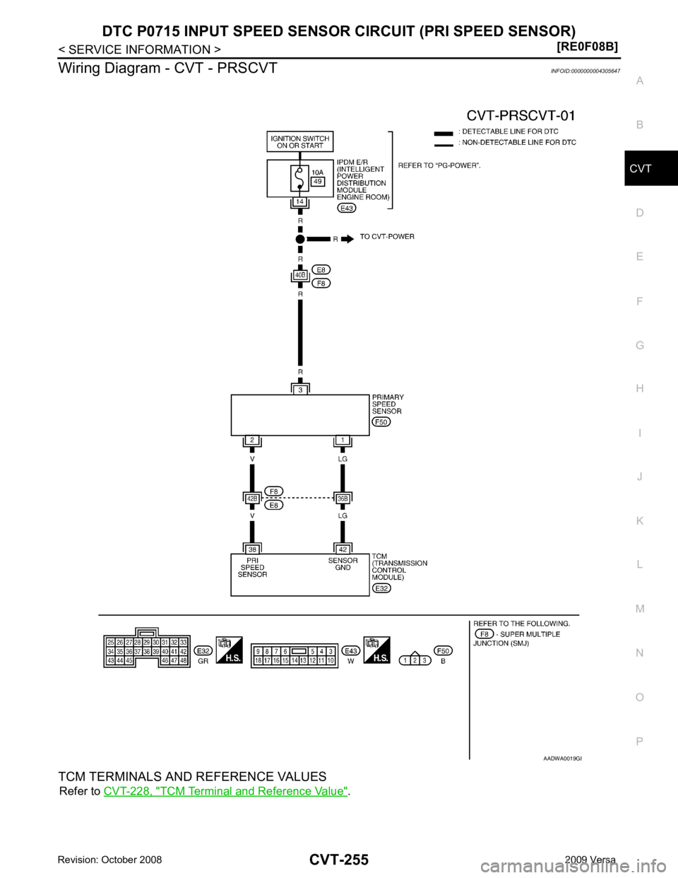
Wiring Diagram - CVT - PRSCVT
INFOID:0000000004305647
TCM TERMINALS AND REFERENCE VALUES Refer to CVT-228, " TCM Terminal and Reference Value " . B
Page 1200 of 4331
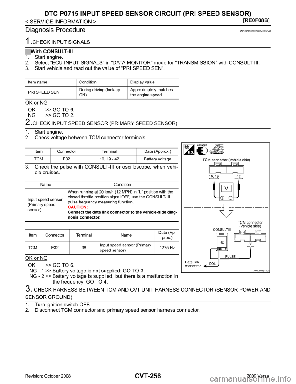
OK >> GO TO 6.
NG >> GO TO 2. OK >> GO TO 6.
NG - 1 >> Battery voltage is not supplied: GO TO 3.
NG - 2 >> Battery voltage is supplied, but there is a malfunction in
the frequency: GO TO 4.
3. CHECK HARNESS BETWEEN TCM AND CVT UNI T HARNESS CONNECTOR (SENSOR POWER ANDItem Connector Terminal Data (Approx.)
TCM E32 10, 19 - 42 Battery voltage
Name Condition
Input speed sensor
(Primary speed
sensor) When running at 20 km/h (12 MPH) in “L” position with the
closed throttle position signal OFF, use the CONSULT-III
pulse frequency measuring function.
CAUTION:
Connect the data link connector to the vehicle-side diag-
nosis connector.
Item Connector Terminal Name Data (Ap-
prox.)
TCM E32 38 Input speed sensor (Primary
speed sensor) 1275 Hz B